Comparison of surface integrity for dry and wet drilling of 49Fe-49Co-2V alloy
Yun ZHANG, Zhigng DONG, Yn BAO, Renke KANG,*, Xin HUANG,Dongming GUO
a Key Laboratory for Precision and Non-traditional Machining Technology of the Ministry of Education, School of Mechanical Engineering, Dalian University of Technology, Dalian 116024, China
b AVIC Xi’an Flight Automatic Control Research Institute, Xi’an 710076, China
KEYWORDS 49Fe-49Co-2V alloy;Cooling condition;Drilling;Exit chipping;Microstructure;Surface integrity;Surface quality;Work hardening
Abstract Working performances of the components made out of 49Fe-49Co-2V alloy are closely related to the surface integrity of the drilled holes, which are influenced remarkably by the cooling conditions. The present study focuses on the surface integrity differences between wet and dry drilled 49Fe-49Co-2V alloy holes.The drilled hole surface roughness and topographies,metallurgical and mechanical properties, and the exit characterizations were obtained using optical microscopy (OM), scanning electron microscopy (SEM), electron backscatter diffraction microscopy(EBSD),transmission electron microscopy(TEM),energy dispersive spectroscopy(EDS)and Vickers hardness techniques, etc. The effects of cooling conditions on the surface integrity were concluded and the influence mechanisms were analyzed based on the force and temperature differences in drilling process with different cooling conditions. It is found that the surface roughness and the thickness of refined-grain region of the dry drilled holes are larger than those of wet drilled holes; work hardening induced by wet drilling is more serious than dry drilling; chippings occurred in the exits of the wet drilled holes due to the material brittleness,which could be avoided by dry drilling. The surface integrity differences of wet and dry drilled holes are closely related to the force and temperature differences in drilling process with different cooling conditions.
1. Introduction
49Fe-49Co-2V alloy has been successfully used in energy conversion applications in the aerospace industry due to its excellent soft magnetic properties including the highest magnetization, high permeability, high Curie temperature and low magnetic losses.In order to meet the function and connection demands, hole-making is indispensable for many components made out of 49Fe-49Co-2V alloy, such as theinner shells of electromagnetic induction sensors, laminations of generator rotors, and shells of solenoid valves. Drilling is a mostly used hole-making method for its low-cost achieving,satisfactory processing quality and acceptable efficiency.In the drilling process, a twist drill is rotated with a high speed around its axis and is fed along the axis,in which the hole surface material must be experienced a mostly plastic deformation with a large strain, a high strain rate and a high temperature.Consequently the microstructure and corresponding mechanical properties of the hole surface material are altered.

Table 1 Chemical components of 49Fe-49Co-2V alloy (wt%).
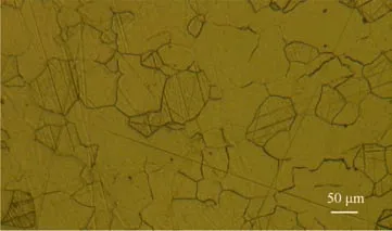
Fig. 1 Metallograph of 49Fe-49Co-2V alloy.
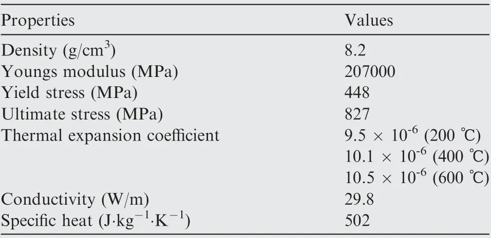
Table 2 Physical properties of 49Fe-49Co-2V alloy.

Table 3 Drilling conditions.
The surface integrity(SI)of the drilled holes can play a key role in determining the working performances of components with holes, such as the fatigue properties,abrasive resistance and magnetic properties. Fatigue is of great concern for components in aerospace industry, which is significantly influenced by SIbecause the fatigue life is related to the surface stress concentration factorand the crack propagation resistance, influenced significantly by the surface topography and metallurgical characterizations respectively.In addition,a hole is usually fitted with a rivet or a bolt,where abrasive resistance is necessary, which is considerably affected by the hardness alterations of the hole surface induced by drilling,such as thermal softening or work hardening.Moreover,49Fe-49Co-2V alloy is an essential soft magnetic material,magnetic properties of which are remarkably related to its metallurgical characterization,influenced considerably by drilling process.For instance, a high-density dislocation region with a thickness of about 100 μm exists in the drilled hole subsurface,which can increase the coercivity of the thin-walled components made out of 49Fe-49Co-2V alloy.
Numerous investigations confirm that the SI of alloys is affected remarkably by cooling conditionsowing to the changing of the process temperature and force. Such as,Pu, et al.found that cooling could reduce the machined surface roughness Rof the AZ31B Mg alloy resulted from the lower temperature. da Silva, et al.reported bigger residual compressive stress of 4340 steel could be gained by wet machining due to the less thermal dilation compared with dry machining. Kwong, et al.found the thickness of the deformation zone induced by dry cutting is larger than wet cutting. Though many researchers have conducted the studies on the influences of machining cooling conditions on the SI of metallic materials,different laws might be obtained in terms of different machining methods and materials. Such as,severer material softening can be generated by dry grinding ABNT 4340 steel compared with wet grinding,while no significant difference in hardness alterations of nickel-base supesralloys between dry drilling and wet drilling.
In the past research, though the microstructural evolution from the hole surface to the inner matrix of the 49Fe-49Co-2V alloy holes drilled and the corresponding strengthening mechanisms had been clarified,the influences of cooling conditions on the SI have not been investigated. Therefore, the present work aims at investigating the drilled surface topography and roughness, metallurgical and mechanical characteristics of subsurface, and the exit quality with different cooling conditions. In addition, the influence mechanism of cooling conditions on the SI of the 49Fe-49Co-2V alloy is discussed in light of force and temperature differences of wet drilling and dry drilling.
2. Experimental details
2.1. Material
The investigated material is the 49Fe-49Co-2V alloy with a typical chemical composition given in Table 1, which is approximately 49% Fe, 49% Co and a small amount of V.
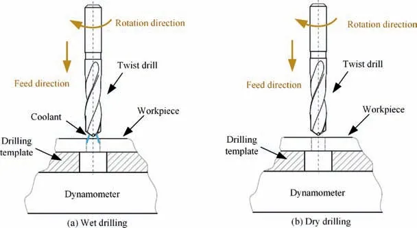
Fig. 2 Schematic diagrams of experimental device under different cooling conditions.
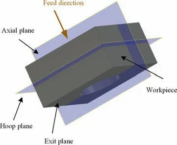
Fig. 3 Observed plane schematic of machined hole.
2.2. Drilling experiments
The drilling experiments were conducted under dry and wet cutting conditions on a five-axis machining center (DMG Ultrasonic 70) using the conditions summarized in Table 3.The inner water based coolant(Castrol Syntilo 9139AA)cooling was used in the wet cutting conditions(as seen in Fig.2(a)).The drilling experiments were repeated for 3 times with every condition listed in Table 3. The solid carbide twist drills with oil holes (XET-600) were used in drilling trials, and the diameter of the drills is 6 mm. To reduce the influence of the tool wear on the test results, every twist drill was used to drill no more than 5 holes. During the drilling process, drilling forces were measured by a dynamometer (9139AA, Kistler). The axial force generated by coolant jetting was previously measured, to be about (3.4 ± 0.3) N, which was subtracted from the measured results of the wet drilling forces.
2.3. Characterization of surface integrity
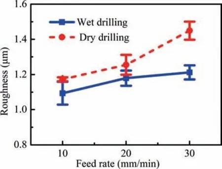
Fig. 4 Variations of roughness with feed rate under different cooling conditions.
The metallographic structure of the alloy is shown in Fig. 1,which is constituted of equiaxed grains with the sizes of about 50-100 μm. The physical properties of this alloy are shown in Table 2. The drilled workpiece is a cylindrical slab with a diameter of 69 mm and a thickness of 16 mm.
The morphologies of the hole surface were observed using the ultra-depth of field optical microscopy (OM) (VHX-600E,Keyence) and scanning electron microscopy (SEM) (Supra55,Zeiss) with an energy dispersive spectrometer (EDS). The topographies of the hole surface were obtained by the white light interferometer (newview 5022 s, Zygo). The surface roughness Sa of the holes was measured using the noncontact laser scanning confocal microscope(VK-X260k,KEYENCE) and the measured area was set as 1 mm × 1 mm. The surface roughness measurements were repeated for three times for each sample.Before the hole surface morphology,topography and the surface roughness obtained, the machined holes had been separated along axial plane(as seen in Fig. 3) by the diamond wire cutting machine and cleaned with alcohol by the ultrasonic cleaner for 10 minutes. The subsurface microstructures of the machined holes were observed by aforementioned SEM and Electron backscattered diffraction(EBSD). The EBSD was conducted using a Zeiss Crossbeam 540 equipped with NordlysMax2 detector and HKL Channel 5 data analysis system at a working distance of 15 mm and accelerating voltage of 30 kV with a step size of 1 μm and the samples were prepared by polishing to a final finish by 0.05 μm colloidal silica and then vibratory polishing.The etching solution used for sample preparation for SEM metallographical observations was constituted of 17 % HNOand 83 % C2H5OH (volume fraction). The thickness of refinedgrain region was measured for no less than 15 times in different regions of each sample by the optical microscopy (OM) mentioned above. Microhardness was measured by a microhardness measurement apparatus (Feima) with a load of 50 g for 10 s at the region where is 30 μm away from the hole wall in hoop plane(as seen in Fig. 2).Microhardness was measured repetitively for no less than thirty times for each sample. For protecting the edges of samples from being destroyed,AB type Epoxy Resin (CM4) and nickel plating were used. The morphologies of the machined hole exits were obtained by OM and SEM,and the sizes of chippings and burrs were measured by the aforementioned laser scanning confocal microscope.The alloy matrix was observed by the transmission electron microscopy (TEM) (G2, Philips Tecnai) equipped with a selected-area electron diffraction(SAED)analysis,and Tecnai F30 scanning transmission electron microscopy (STEM). The TEM samples of the alloy matrix were prepared by twin-jet electro-polishing in a solution of 4% HClO4 + 96%C2H5OH (volume fraction) at about minus 30 ℃.
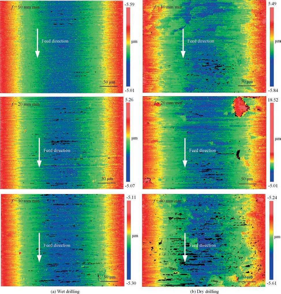
Fig. 5 Surface topographies of holes machined with different cooling conditions.
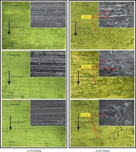
Fig. 6 Surface morphologies of holes machined with observed by OM and SEM.
3. Results
3.1. Surface roughness and topography
The surface quality of machined holes can remarkably influence the working capability of components. Fig. 4 exhibits the surface roughness Sof holes drilled with different cooling conditions (wet drilling and dry drilling). It could be found that the surface roughness Sof the drilled holes varies between 1 μm and 1.5 μm and grows with the increase of feed rate. Moreover, the surface roughness Sof wet drilled holes with all three feed rates are all smaller than that of dry drilled holes.To be more specific,the Sof dry drilled holes machined with f = 10 mm/min, 20 mm/min, 30 mm/min are 1.17 μm,1.26 μm and 1.45 μm respectively, whereas, these corresponding values of wet drilled holes are 1.09 μm, 1.18 μm and 1.21 μm, the mean value of which (1.16 μm) is 10.1% smaller than that of dry drilled holes (1.29 μm).
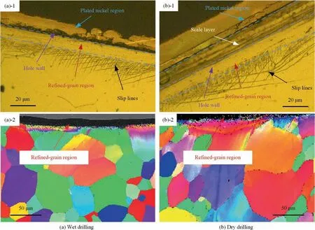
Fig. 7 Morphologies of the region on surface layer of holes observed by OM ((a)-1, (b)-1) and EBSD ((a)-2, (b)-2).
The surface topographies of the holes are shown in Fig. 5,in which it could be found that the hole surfaces of dry drilling are more irregular than those of wet drilling,where only regular cutting marks which are perpendicular to the tool feed direction exist. Fig. 6 shows the drilled surface morphologies observed by OM and SEM, where it could be found that the wet drilled surfaces consist of uniform cutting marks which are consistent with the results of Fig.5.In contrast,apart from the cutting marks, there are many lamellar scales adhering to the dry drilled surface, which may be the main reason for the irregular of surfaces and the increases of surface roughness Sof dry drilled holes (as seen in Fig. 4), compared with the wet drilled holes.
3.2. Microstructures and microhardness at the drilled surface
Typical microstructural morphologies in the subsurface of the drilled holes observed by OM and EBSD in hoop plane(Fig.3)are shown in Fig. 7. It could be found that the subsurface of the holes machined by both wet drilling (Fig. 7 (a)) and dry drilling (Fig. 7 (b)) are constituted of refined-grain region and plastic deformation region (a number of slip lines contained), which is consistent with the previous investigation results.Besides, there is a scale layer(marked with the white arrow in Fig.7(b)-1)with a thickness of about 10 μm to 20 μm adhering to the hole surfaces of dry drilling at some areas.As a supplement, we also mapped the chemical distribution of elements in the subsurface of the dry drilled hole, as seen in Fig. 8. It could be found that this redundant layer is mainly composed of Fe and Co instead of Ni, which illustrates that it has the same element components with the machined material, indicating this layer is the scale rather than the plated material.
The OM images of the subsurface of drilled holes with different cooling conditions and drilling parameters are shown in Fig. 9. The refined-grain regions were between the white lines, marked with the white arrow (Fig. 9). Due to the existence of the refined-grain region is influential in the working performance of the alloy,its thickness variation tendency with the feed rate and cooling conditions is investigated,which is shown in Fig. 10. It could be found that the thickness of the refined-grain region varies from 1 μm to 18 μm and increases with the increasing of the feed rate f from 10 mm/min to 30 mm/min. Moreover, the thickness of the dry drilled holes is always larger than that of wet drilled holes. The mean thickness of the dry drilled holes with different feed rates is 7.8 μm, which is nearly twice of the wet drilled holes (3.6 μm).
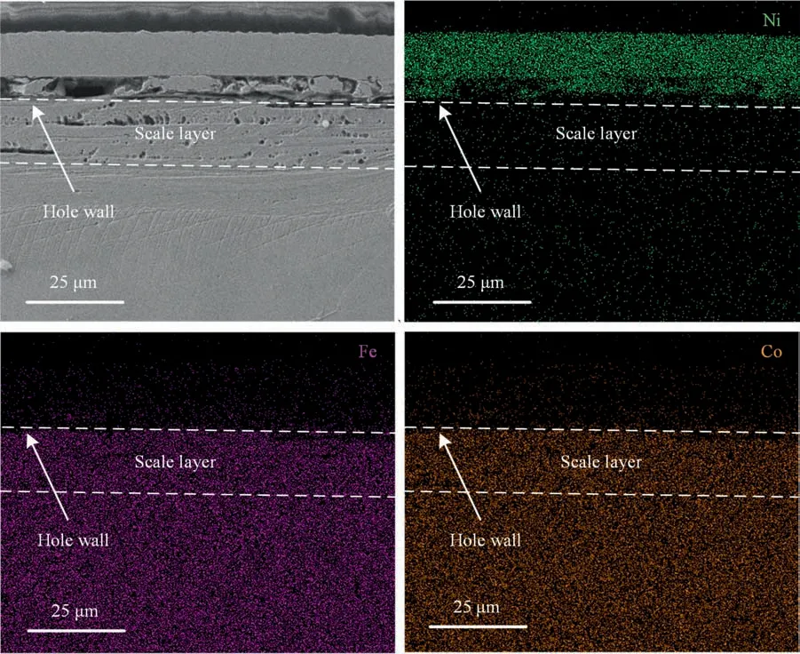
Fig. 8 Elemental distribution in subsurface of dry drilled hole of 49Fe-49Co-2V alloy.
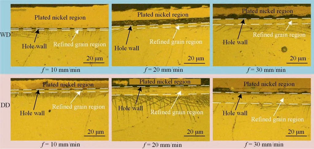
Fig.9 OM images in the subsurface of drilled holes with different cooling conditions and drilling parameters.(WD:Wet Drilling;DD:Dry Drilling).
Obvious work hardening appears in the drilled hole surface of the 49Fe-49Co-2V alloy.The influence of cooling conditions on the microhardness of surface layer is shown in Fig. 11. It should be noted that the microhardness of the hole surface was measured at the region which is 30 μm beneath the hole wall in hoop plane(as seen in Fig.3),and the microhardness measured of the matrix material is 308 ± 12.4 HV. It could be found that the surface microhardness of dry drilled holes is slightly less than that of wet drilled holes (as seen in Fig. 11). The mean microhardness of the dry drilled holes is 446 HV, which is 7 % less than that of dry drilled holes(478 HV). Besides, it could also be seen that with the feed rate f increasing,the work hardening of hole wall layer is more and more serious.
3.3. Exit quality
The exit quality of machined holes is closely related to the assembly precision and working performances of components with holes, therefore it was investigated. As shown in Fig. 12,the exit morphologies of holes observed in exit plane (seen in Fig. 3) of drilling were observed by OM. It could be seen that there are serious chippings in the exits of the holes machined by wet drilling (seen in Fig. 12 (a)) and there are only some small size burrs in the exits of the dry drilled holes (seen in Fig. 12 (b)). The exit topographies of machined holes are shown in Fig. 13, where it could be found that the depth of the exit chippings of wet drilled hole is about 100-200 μm and the exit burr height of the dry drilled holes is about 50-150 μm.
The subsurface morphologies at the hole exits in axial plane(as seen in Fig.3)are shown in Fig.14.It could be found that there are cracks close to the exit chippings of the wet drilled holes(marked with yellow arrows in Fig.14(a)),which is seriously harmful to the working performance. In contrast, few cracks appear in the subsurface of the dry drilled holes,instead, where obvious slip lines exist (marked with purple arrows in Fig.14(b)),indicating considerable plastic deformation happened here.
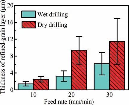
Fig. 10 Refined-grain thickness of hole wall layer under different cooling conditions.
4. Discussion
The material removal is a mostly plastic behavior in drilling process,when the microstructure and mechanical properties of material in the hole surface altered due to the large force and high temperature,influenced directly by cooling conditions.
4.1. Influence of cooling conditions on the drilling force and temperature
Drilling forces were measured in order to analyzing the influence mechanisms of surface integrity. It could be found that the axial forces of dry drilling 49Fe-49Co-2V alloy are obviously smaller than those of wet drilling (as seen in Fig. 15).It is well accepted that the cutting force originates mainly in three aspects, including the shear deformation of the material to be removed (F), the friction between a tool and chips (F)and the ploughing of the machined surface(F),among which,the ploughing force Fcould be ignored due to it is far smaller than those originated from the former two aspects (Fand F)).The friction force Fof wet drilling should be smaller than that of dry drilling because the coolant could reduce the friction coefficient between the cutting tool and the chips.Thereof, the chip deformation forces Fof dry drilling 49Fe-49Co-2V alloy should considerably be smaller than the forces of wet drilling,which should be attributed to the more serious material thermal softening in dry drilling process. Thermal softening of the material is resulted from the high temperature(0.16-0.9 T)in drilling process.The applying of coolants could decrease the machining temperature by 10-40 percent.In comparison with dry drilling, the temperature could be reduced by 15-20 percent when water based coolant is used.
4.2.Influence of cooling conditions on surface quality of the hole wall
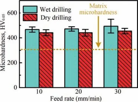
Fig.11 Microhardness of the drilled hole surface under different cooling conditions.
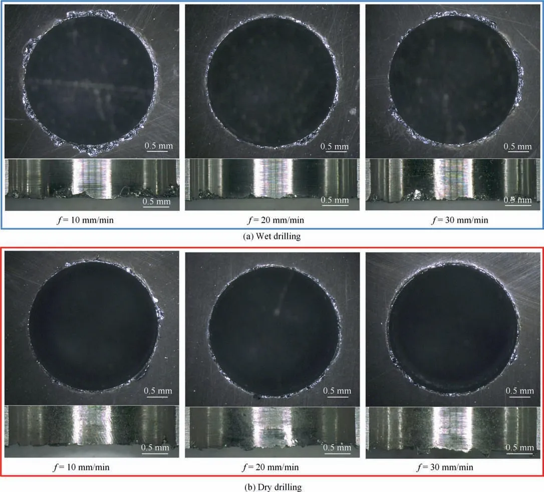
Fig. 12 Exit morphologies of holes machined with different cooling conditions observed by OM.
There are many scales on the dry drilled surface,but few scales appear in the wet drilled surface(as seen in Fig.6),which contributes to higher surface roughness of dry drilling than that of wet drilling(as seen in Fig.4).Scales originate from the adhering of chipping to the cutting edge and further to the machined surface due to the big friction force and high temperature generated by cutting.The formation of scales is influenced mainly by two main factors: workpiece material properties and the friction between the cutting tool and the chips.Firstly,the metal material should be ‘‘soft” enough, when its strength is low and it is easier to be deformed and adhered to the surface of the tool and machined surface. Besides, the friction force between the chip and tool surface should be large enough to stop the slide of chips on the cutting tool surface and be adhered there. In fact, the use of the coolant could reduce or avoid the both above two situations happened because both the material thermal softening and friction force could be reduced as discussed in 4.1. Therefore, if the scales on the drilled surface of the 49Fe-49Co-2V alloy want to be avoided,the applying of coolant will be necessary.
4.3. Influence of cooling conditions on the microstructure and microhardness in the subsurface
In the region close to the hole wall,severe plastic deformation occurred during the drilling process,leading to a huge number of dislocations appearing, contributing to the microhardness increasing according to Bailey-Hirsch dislocation strengthening mechanism,as:

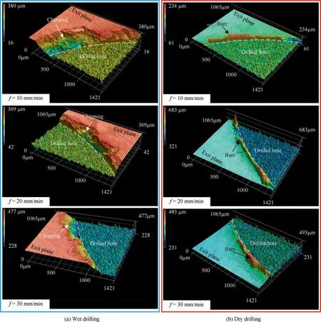
Fig. 13 Exit topographies of holes machined with different cooling conditions.
where ΔH is the hardness increment;α is the Tabor factor;Δσis the yield strength increment;M is the Taylor factor;αis the dislocation strengthening coefficient;G is the shear modulus;ρ is the dislocation density; and b is the burger vector. Furthermore,the dislocation density(ρ)is approximately proportional to the square of plastic strain (ε) according to the Eq. (2):

Therefore,it could be concluded that with the increasing of the plastic stain ε, the hardness induced increases. According to the Fig. 11, the work hardening induced by wet drilling is more serious than that of dry drilling, indicating the residual strain in the subsurface layer of the wet drilled hole is bigger than that of the dry drilled hole. This may be resulted from the bigger force of wet drilling, as mentioned in 4.1. Besides,the higher temperature of dry drilling also promotes the recovery and recrystallization(as seen in Figs.9,10)happened in the subsurface layer, contributing to the reduction of work hardening.
4.4. Formation mechanisms of exit cracks, chippings, and the influence of cooling conditions
It could be seen in the Figs. 12, 13 that there are cracks in the exits of wet drilled holes, which may influence remarkably the machining efficiency and working ability of the components.So it is necessary to analyze the formation of the cracks.
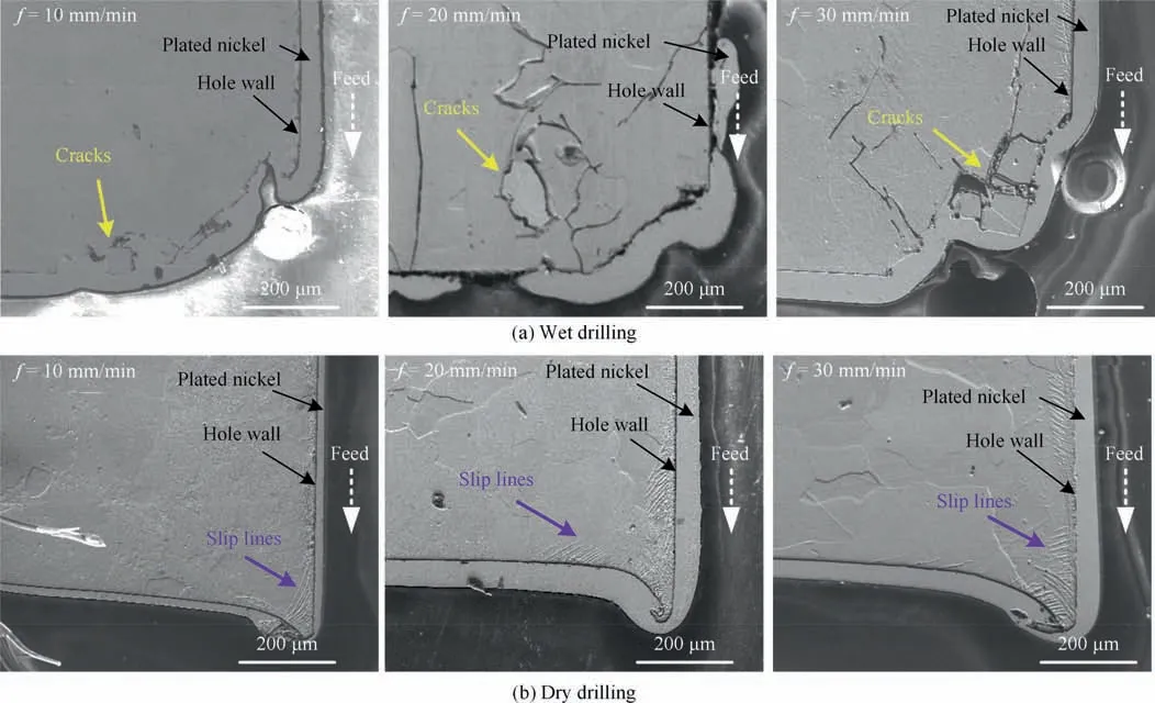
Fig. 14 Exit subsurface morphologies in axial plane of holes machined with different cooling conditions.
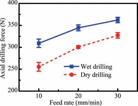
Fig. 15 Variations of axial force with feed rate under different cooling conditions.
Firstly, the appearance of cracks is related to the alloy property.It is well known that most of metal materials exhibit good plasticity and resultantly burrs or flashes occur in the exits of machined holes.However, cracks appearing in the subsurface of the wet drilled holes of 49Fe-49Co-2V alloy presents shows the brittleness of the alloy. Therefore the crystal structure of this alloy is analyzed further and it could be found that the equiatomic Fe-Co alloy exhibits ordered B2 structure(Fig.16(c))when temperature is under 730 ℃according to the Fe-Co binary phase diagram (Fig. 16 (a)).The ordered B2 structure is significantly more brittle than its disordered solid solution body centered cubic (BCC) structure (Fig. 16 (b))due to the covalent bond existing in B2 structure.For ensuring the ordered B2 exists, the microstructure of the workpiece material was observed by TEM. As seen in Fig. 10, both the disordered BCC and ordered B2 phase could be found according to the SAED pattern(Fig.17(b))though few obvious precipitation particles seen in the bright-field image (Fig. 17 (a)).As discussed above,it could be concluded that the 49Fe-49Co-2V alloy is constituted of not only the metallic bond but also the covalent bond due to the existence of the ordered B2 phase,which contributes to the brittleness.In addition,the load state also leads to the propagation of cracks. As seen in Fig. 2, the bottom of drilled region was suspended.So compared with the upper region, this region would experience larger tensile stress in drilling process, promoting the crack propagation.
For investigating the formation mechanism of the chippings, the microscopic morphology of the wet drilled hole was observed in exit plane (Fig. 3) by SEM, as shown in Fig.18,where a number of river patterns reserved,illustrating that brittle fracture of the alloy is the main reason of the chipping. In addition, intergranular fracture and transgranular fracture could both be found at the exit chipping region(Fig. 18). Therefore, it could be speculated that the chipping will be formed when the cracks propagate to the surface of the workpiece, leading to the falling off of bulk material in the exit region.
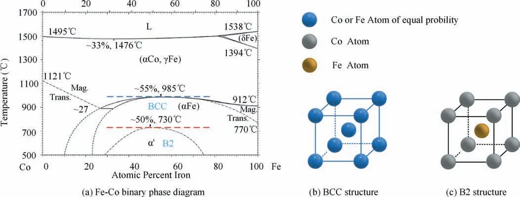
Fig. 16 Crystal structures of Fe-Co alloy.
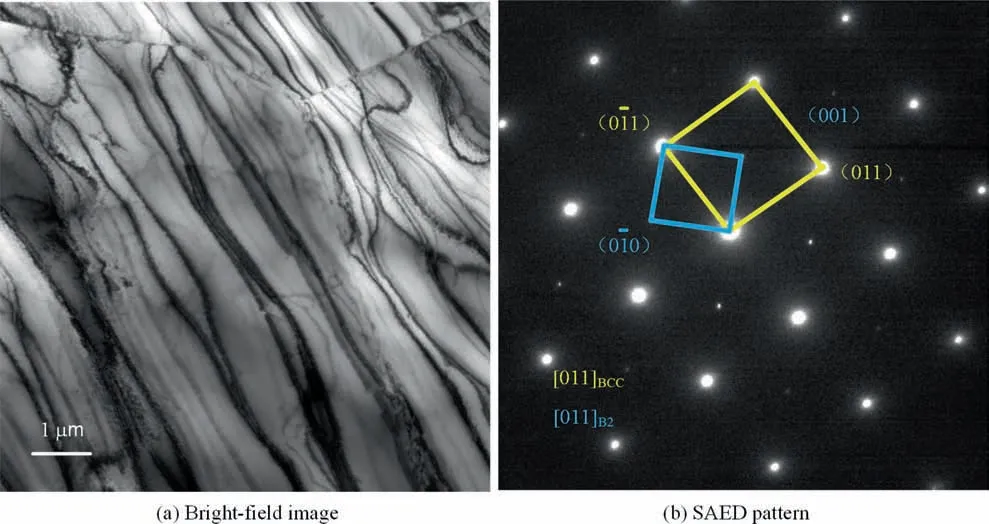
Fig. 17 TEM results of the 49Fe-49Co-2V alloy.
Machining cracks and chippings are also influenced considerately by force and temperature loads applied in the machining process.Such as,it is exciting that the cracks and chippings could significantly be reduced by dry drilling(Figs.12-14).As discussed in 4.1, the axial force of dry drilling is smaller than that of wet drilling, which could contribute to the reduction of cracks and chippings. Moreover, the temperature of dry drilling is higher than that of wet drilling (discussed in 4.1),which could improve the material plasticity, and resultantly the exit cracks and chippings are reduced by the dry drilling.
5. Conclusion
The surface integrity of the drilled holes of the 49Fe-49Co-2V alloy was characterized using OM, SEM, EBSD and Vickers hardness techniques for dry and wet cutting conditions, and the influence mechanisms of cooling conditions on the surface integrity were analyzed based on the force and temperature differences in different cooling conditions. The following conclusions are drawn.
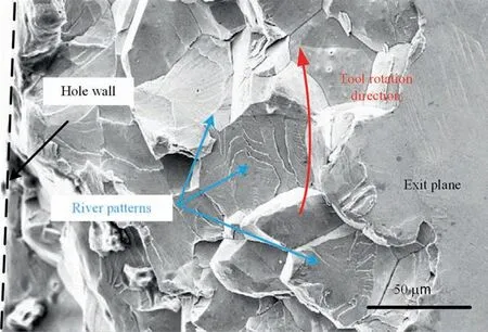
Fig. 18 Microscopic morphology of wet drilled hole observed by SEM.
(1) The smaller drilling forces are generated by dry drilling compared with wet drilling.
(2) The surface roughness of the drilled holes could be reduced by using the coolant.
(3) The subsurface of holes machined by both wet drilling and dry drilling are constituted of refined-grain region and plastic deformation region. Besides, there is a scale layer at some areas of the dry drilled holes.
(4) The work hardening of the holes of wet drilling is more severe than that of dry drilling.
(5) Refined-grain region induced by dry drilling is thicker than that by wet drilling.
(6) The exit chippings exist in the exits of wet drilled holes,but could be avoided by dry drilling.
The authors declare that they have no known competing financial interests or personal relationships that could have appeared to influence the work reported in this paper.
This study was co-supported by the National Science and Technology Major Project (No. 2017-VII-0002-0095), the Science Challenge Project (No. TZ2018006-0101-01) and the Postdoctoral Science Foundation (No. 2019M661090).
 Chinese Journal of Aeronautics2022年6期
- Chinese Journal of Aeronautics的其它文章
- Experimental investigation of a gliding discharge plasma jet igniter
- Evolution of turbulent boundary layer over a three-dimensional bump
- Conceptual design and preliminary experiment of icing risk management and protection system
- Direct thrust control for multivariable turbofan engine based on affine linear parameter-varying approach
- Characteristics of reattached boundary layer in shock wave and turbulent boundary layer interaction
- Structurally coupled characteristics of rotor blade using new rigid-flexible dynamic model based on geometrically exact formulation
