Experimental investigation of a gliding discharge plasma jet igniter
Min JIA, Zhibo ZHANG,b,*, Wei CUI, Huimin SONG, Zhngki HUANG
a Science and Technology on Plasma Dynamics Laboratory, Air Force Engineering University, Xi’an 710038, China
b Key Laboratory of Physical Electronics and Devices of Ministry of Education, Xi’an Jiaotong University, Xi’an 710038, China
KEYWORDS Gliding Arc Plasma Jet Igniter (GAPJI);Arc evolution;Flame kernel;Ignition process;Gliding arc;Lean ignition limit
Abstract Relight of jet engines at high altitude is difficult due to the relatively low pressure and temperature of inlet air. The penetration of initial flame kernel affects the ignition probability in the turbine engine combustor greatly.In order to achieve successful ignition at high altitude,a deeper penetration of initial flame kernel should be generated. In this study,a Gliding Arc Plasma Jet Igniter(GAPJI)is designed to induce initial flame kernel with deeper penetration to achieve successful ignition at high altitude. The ignition performance of the GAPJI was demonstrated in a model combustor. It was found that GAPJI can generate plasma with deeper penetration up to 30.5 mm than spark igniter with 22.1 mm.The discharge power of GAPJI was positively correlated with flow rate of the carrier gas, approaching 200 W in average. Ignition experiments show that GAPJI has the advantage of extending the lean ignition limit. With GAPJI, the lean ignition limit of the combustor is 0.02 at 0 km, which is 55.6% less than that with spark igniter (0.045). The evolution of flame morphology was observed to explore the development of the flame kernel. It is shown that the advantage of a high penetration and continuous releasing energy can accelerate the ignition process and enhance combustion.
1. Introduction
Plasma is the fourth state of matter.With its thermal effect,transport effect and kinetic effect, plasma has broad application prospects in aviation engine ignition and combustion.The ignition experiment with gaseous fuels of methane and ethylene conducted by Bao et al. has shown that active particles such as O and OH generated by plasma play a key role in the chemical reaction process, which can reduce the Minimum Ignition Energy (MIE) and shorten the ignition delay time.In recent decades, gliding arc discharge has been widely studied in plasma assisted ignition and aiding combustion. Ombrello et al. has researched the effect of a stabilized piecewise non-equilibrium gliding arc discharge on a diffusion flame at low air temperatures.Direct comparisons of the extinction limits and temperature and OH distributions between the experimental and numerical simulations demonstrated that the aiding combustion at a low-power discharge in the airstream was dominated by thermal effect. The electronic, vibrational, and translational gas temperatures in the nonequilibrium regime of a gliding arc discharge were approximately 10000, 2000-3000, and 800-2100 K, respectively.Zheng and Wang has compared the flame acceleration in single-trial dual-detonation tubes triggered by a spark plug and non-thermal plasma igniter.Results showed that the deflagration-to-detonation transition could be significantly accelerated by the plasma for all mixtures, as it was shortened by more than 50% compared to that of the spark plug. The experiments conducted by He et al. has shown that the combustion efficiency is improved after plasma-assisted combustion compared with that in normal conditions.
Plasma jet igniter has the advantage of great penetration depth of initial flame, high temperature active particle, and shorter ignition delay time compared to spark igniter. The characteristics of plasma jet have been investigated for years.Takita et al. found that in a square combustor with subsonic air flow up to 80 m/s,the ignition limit decreased with increasing the distance between the fuel injector and the plasma torch and steeply decreased with increasing airflow velocity.The results suggested that the penetration depth of plasma jet strongly affects the ignition limit.Liu et al.studied the performance of the plasma jet igniter in one can-annular combustor of the gas turbines.The result suggested that the increase of the plasma jet flow length and discharge frequency can benefit kernel growth and flame propagation.Jacobsen et al.used the Planar Laser-Induced Fluorescence of Nitric Oxide (NOPLIF) to test the energy released by the plasma igniter, suggesting that with an input power of 2 kW, a plasma igniter can produce hyperthermal gas of 5000 K,which forces the kerosene to evaporate.What’s more, fresh air has a larger contact area with the fuel and increases the ignition probability.Using Coherent Anti-Stokes Raman Spectroscopy (CARS)and schlieren images, Pfender et al. found that the plasma jet has a process of entrainment and turbulence in the peripheral flow field.The injected air also affects the mainstream of combustor. Sato et al’s experiments have demonstrated that plasma torch using incoming air or onboard propellants as feed stock is effective for ignition and flameholding in a scramjet combustor.Zhang et al. found that the plasma jet contains abundant active particles inferred from the emission spectrum.Kim et al’s work suggested that the assisted combustion performances of the arc and jet plasma discharges are noticeable in that flame thickness, and velocity characteristics could be affected by ionized kernels.What’s more, the Electromagnetic Interfaces (EMI) caused by discharge is another problem in practical application.It is known that the steep rise edge of repetitively pulsed plasma induces EMI for electronic instrumentation.As for the gliding arc discharge, the sine-waves high voltage power supply is used, and the typical frequency of the sine-waves is on the order of 1-10.Furthermore, the discharge peak current of gliding arc discharge is always less than 10 A. But the discharge peak current of the conventional spark igniter is larger than 100 A. Therefore,the EMI caused by gliding arc discharge is weaker.
To further reveal the characteristics of the gliding discharge plasma igniter and its ignition performance in swirl combustor,a gliding arc plasma jet igniter is designed to increase the penetration depth and a larger ignition kernel size to achieve successful ignition in a combustor. The discharge characteristics and ignition ability of GAPJI were measured.CH*chemiluminescence and lean ignition limit in combustor were obtained.To further study the mechanism of GAPJI ignition,the evolution of flame morphology with GAPJI and traditional spark igniter is obtained by a high speed camera.
2. Experiment setup
The schematic diagram of the GAPJI used in the experiment is shown in Fig. 1, which is mainly composed of a cathode, an anode, a swirl vane and a special-shaped ceramic. The anode,made of superalloy,is divided into an anode head and a mount,which employed a thread joint to connect.The diameter of the anode head is 6 mm and the length of it is 11.4 mm.The cathode is fabricated by metal additive manufacturing technology and printed integrally with swirl vane. The external dimension of the igniter is 19.5 mm, and at the middle of the igniter is an 8 mm wide inlet port.The ceramics are made of alumina ceramics.A-A profile means the cross-section of the jet chamber outlet.
As indicated in Fig. 2, the igniter experimental system is mainly composed of GAPJI,gliding arc plasma power supply,gas supply system, measuring equipment and data acquisition system. A high voltage sinusoidal wave supply is adopted to drive the GAPJI,maintaining the plasma arc in a low current.The gas supply system adjusts the gas flow of carrier gas by an air compressor and a volume flow meter in a range of 0-400 SLM (Standard Liter per Minute). To quantify the ignition energy, the discharge voltage and current were monitored by a digital oscilloscope(Tektronix DPO4014,1 GHz bandwidth,2.5 GS/s sampling rate) through a HV probe (Tektronix P6015A, 75 MHz bandwidth) and a current probe (Tektronix P6021,120 MHz bandwidth).The gliding arc images were captured by a high-speed CMOS camera (Phantom V12.1). The frame rate and resolution are set as 40000 frame/s and 512 pixel × 512 pixel, respectively.

Fig. 1 Schematic diagram of structure of GAPJI.
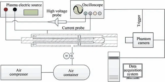
Fig. 2 Schematic diagram of igniter experimental system.
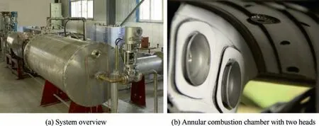
Fig. 3 High-altitude relight test facility.
To explore the ignition process of GAPJI, a high-speed CMOS camera (Phantom V12.1) was used to capture the evolution progress of the ignition kernel. As shown in Fig. 3, a high-altitude relight test facility is adopted to study the relight performance of the GAPJI from the ground to 12 km. An annular combustion chamber with two heads is used.The igniter is located between two atomizers. The fuel is driven by the pressure supply system, ranging from 0 MPa to 0.5 MPa. The ignition limit is described by Fuel-Air Ratio (FAR). In the experiments,the discharge duration time of the GAPJI is only 3 s. If a stable flame can be stabilized after the plasma is off,ignition is considered successful. To improve the accuracy of the ignition experiment, three ignition attempts were made at the same ignition condition. And as long as one ignition attempt fails to ignite,it is considered the GAPJI fails to ignite at this condition.
3. Results and discussion
3.1. Evolution progress of gliding arc
The discharge images of GAPJI are captured, as shown in Fig. 4(a). After the power supply turns on, the gap between the anode and the cathode is arced randomly. Subsequently,the arc continuously stretches with the help of swirling gas.Since the flow is swirling, the arc continuously rotates clockwise inside the jet chamber. As the arc grows, the cathode point of the discharge also rises. The sixth picture of Fig. 4(a) is obtained at the moment when the cathode point is at the exit of the igniter. The rotation angle of the cathode point is measured and plotted in Fig.4(b).When the cathode point is in the igniter chamber, the rotation frequency keeps fixed,about 7.24 rad/s. But when the arc continues to stretch with the swirling gas outside the jet chamber,the arc’s rotation frequency is significantly reduced.When the arc channel stretches to a certain length, the output power of the power supply system cannot maintain the discharge, the arc channel extinguishes and reignites. The certain length when the arc channel will extinguish is defined as the length of the plasma jet. The detailed discussion is presented in Section 3.2.2.
18. Came to a large town: Zipes translates it as city (Complete 193).According to Biedermann, in the symbolgoly of the psyche61, the city stands for the regularized center of a person s life, which can often be reached only after long travels, when a high degree of emotional maturity62 has been attained63 and the gate to the spiritual center of one s life can be traversed (72).

Fig. 4 Arc evolution on front side of a gliding arc plasma jet igniter.
3.2. Discharge characteristics
3.2.1. Voltage and current profiles
The discharge voltage and current waveforms of the igniter under the airflow of 20 SLM are shown in Fig.5.The zero time point is characterized as the start time of breakdown, which can be detected by the discharge current.The GAPJI discharge process is divided into three stages.The first stage is the breakdown phase: the gliding arc plasma power supply starts to work. Before the breakdown of the igniter, the whole igniter can be regarded as a capacitor, the voltage is continuous in a sine wave, and the current is almost zero. At some time, the voltage across the electrodes is over the breakdown voltage,the gap is broken down and an arc is generated. Then discharge current can be detected. This phase has been indicated in Fig. 5(a). The second stage is the arc development phase.With the swirling air, the arc is continuously rotated and stretches after the arc is formed.The third stage is the fracture phase.After the arc stretches to a certain length,the arc extinguishes due to the power supply limitation. At that moment,the discharge voltage would decrease quickly, which is indicated in Fig. 5(a).
To reveal the relationship between the arc evolution and the discharge voltage,a time-correlation diagram of the arc image and voltage are collected by the high-speed camera and the oscilloscope,as shown in Fig.6.It is suggested that the length of an arc is positively correlated with the voltage.As the arc is continuously elongated by the air, the voltage rises.
It is worth mentioning that the current does not show a pulse increase when a re-breakdown occurs. Because the arc does not completely extinguish before the next discharge cycle begins. The re-breakdown process is obtained in details. As shown in Fig.7,the arc begins to develop a new arc at the next breakdown point. So the original arc creates a new arc in the breakdown phase.But the length of the new arc is shorter than the original arc.Therefore,the voltage waveform on the oscilloscope shows a sudden drop, but the current was maintained at around 0.5 A.
3.2.2. Plasma jet characteristics
The length and power of the plasma jet in GAPJI are important parameters. The length determines the penetration depth of the jet and the disturbance intensity to the mainstream.With a larger penetration depth and stronger disturbance intensity, it is more likely for an arc to reach the appropriate equivalence ratio area in the combustion chamber,which leads to successful ignition. The arc power has an important role in the size of the initial ignition kernel.It has been validated that the larger the initial ignition kernel is, the better the ignition performance of the igniter is.
Fig. 8 shows the relationship between the length of the plasma jet and air flow rate. As the air flow rate is less than 15 SLM, the length of arc increases to 30.5 mm gradually.As the air flow rate is greater than 15 SLM, the length decreases with increasing air flow rate. The reasons are as follows. The increase of gas flow rate leads to the increase of gas flow velocity, which accelerates the drift and diffusion of conductive particles between electrodes and reduces the density of electrons and ions between electrodes. What’s more, the airflow with higher velocity accelerates the heat exchange rate between the discharge channel and the around the air. As a result, the local temperature decreases, which accelerates the energy dissipation process. The joint action of these factors increases the instability of the arc.When the air flow rate is less than a certain value(15 SLM in this experiment),the influence of flow rate on the arc instability is not prominent. The arc height increases with increasing the air flow rate. However,when the air flow rate exceeds 15 SLM, the instability of the arc increases with the increasing flow rate.The discharge channel is easy re-breakdown, leading to a decrease in the arc height.
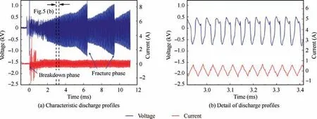
Fig. 5 Discharge voltage and current profiles.
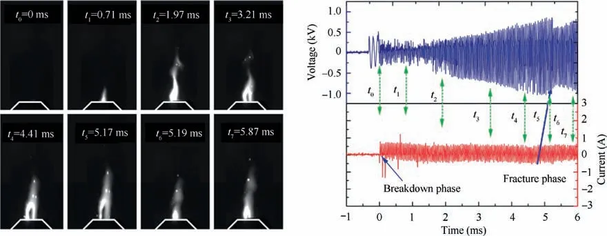
Fig. 6 Time-correlation diagram of arc and voltage waveform.

Fig. 7 Arc re-breakdown process.
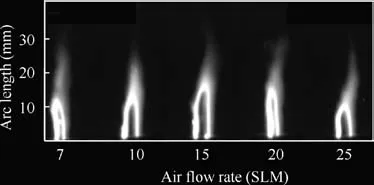
Fig. 8 Variation of arc length with different air flow rate.
To validate this explanation, the power released by igniter and discharge cycle is obtained from the discharge waveforms,as shown in Fig. 9. As shown in Fig. 9(a), when the air flow rate is less than 15 SLM, the discharge power increase with increasing the air flow rate.However,as the power supply system is limited, the power supply system cannot maintain the high power discharge. So the discharge channel is easy to rebreakdown, and the actual maximum discharge power almost keeps fixed.
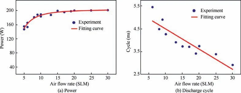
Fig. 9 Power released by igniter and discharge vs air flow rate.
For the same reason, the increment of circumferential velocity accelerates the distortion of the plasma arc, which breaks the arc more quickly. After the arc breaks, a new arc occurs through the air again, and begins to grow in the new cycle. As a result, the duration time of one discharge cycle decreases with increasing the air flow rate.
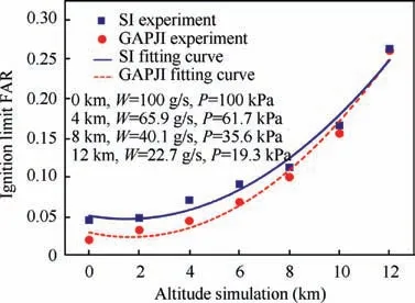
Fig. 10 Lean ignition limit with SI and GAPJI.
3.3. Ignition process of GAPJI
To obtain the ignition performance of GAPJI, the lean ignition limits of the GAPJI and a traditional Spark Igniter (SI)are obtained at different conditions, as shown in Fig. 10. In this figure, W is the flow rate of combustion chamber inlet gas,P is the total pressure of the inlet gas.SI operated in pulse mode with a frequency of 3 Hz. Each pulse’s energy was 12 J.With increasing the simulated altitude of the combustor, the ignition conditions inside the combustion chamber gradually deteriorate, so the lean ignition limit rises rapidly. The lean ignition limit based on FAR is used to evaluate the ignition performance of the igniter. The fuel flow rate is measured by a mass flowmeter (promass 80A, maximum measured error:0.15%).The inlet gas flow rate is measured by a mass flowmeter (Proline Prowirl F 200, maximum measured error: 1.7%).The FAR is defined as the ratio of the mass of fuel to the mass of the air.Based on the error analysis theory,the measurement error of the ignition limit FAR is 1.7%. The effect of altitude on FAR is very significant.For spark igniter,the lean ignition limit for 0 km is 0.045, while the ignition limit for 12 km is 0.26.The FAR increases 477.8%. Under the same intake conditions,the gliding arc plasma jet igniter extends the lean ignition boundary. The lean ignition limit of the GAPJI in the simulated altitude of 0 km is 0.02. The FAR decreases 55.6% compared with SI. As the simulated altitude increases,the penetration depth of the plasma jet is shorter. So the lean ignition limits of two igniters are getting close.But the GAPJI still extends the FAR around 38.1%, 11.6%, 6.7% for 4 km,8 km and 10 km.
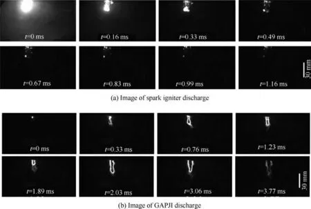
Fig. 11 Comparison of penetration depth between SI and GAPJI.
To better understand the ignition process with the different igniter, the discharge images and ignition images are obtained with a high-speed camera. The typical discharge image sequences of the spark igniter and the GAPJI are shown in Fig. 11. The inlet gas flow rate and altitude are 100 g/s and 0 km, respectively. The high temperature gas reaches a maximum penetration depth of 22.1 mm when t = 0.16 ms, but the projection area of the spark is small and the hot gas dissipates in the combustor flow quickly. The development of the arc of GAPJI is basically perpendicular to the exit of the igniter. The jet igniter has a penetration depth of 29.7 mm at t = 2.03 ms, almost half of the combustor chamber depth.So the plasma arc reached the center of the recirculation zone in the combustor chamber, which would benefit the successful ignition.
Fig. 12 shows the evolution of flame morphology recorded by high-speed camera with different igniters. As the luminous intensity of the ignition process taken by the black and white camera is too weak to get detailed information of the flame kernel, the pseudo-color processing is carried out on the original gray-scale images. The simulated altitude is 4 km. The flow rate of fuel and combustor inlet air are 4.8 g/s and 65.9 g/s, respectively. So the FAR is 0.073. As shown in Fig. 12(a), after the discharge occurs, a large initial flame kernel forms.However,as the duration time of spark discharge is less than 1 ms, the igniter cannot output energy to the flame kernel soon. At the initial stage, the high temperature of the initial flame kernel increases the heat exchange with the ambient gas and the radiation. As a result, heat generation produced by the chemical reactions inside the gas kernel is less than the heat loss of flame kernel. Therefore, the flame kernel shrinks gradually. Meantime, under the influence of the recirculation region,the flame kernel propagates toward the center of the injector. With the decrease of the flame kernel size, the flame becomes weaker. After a special residence process with the flame kernel remaining weak at the center of the injector,the flame grows axially and then radially until the flame stabilizes in the center.
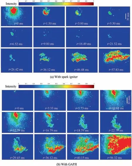
Fig. 12 Evolution of flame morphology at simulated altitude of 4 km, FAR = 0.073.
However,the evolution of flame morphology with GAPJI is completely different. At the beginning of the ignition process,the initial flame kernel is very small compared with that produced by SI. But, as the GAPJI can continuously output energy for a long time, the flame kernel becomes larger and brighter. What’s more, there is no residence process with the weak flame kernel, as shown in Fig. 12(a) from 9.00 ms to 21.52 ms.Then,the flame grows axially and then radially until the flame stabilizes in the center. As flame intensity is maintained at a relatively high level throughout the ignition process, it is more likely for the flame to achieve stable combustion. This is the reason why the GAPJI can have a wider ignition limit.
4. Conclusions
In this paper, a new type of gliding arc GAPJI is designed to increase the penetration depth of plasma and extend the lean ignition limit of the conventional spark igniter. Discharge experiments are conducted to explore the basic characteristics of GAPJI. The high-speed camera is used to record the spatial-temporal evolution of the gliding arc and the ignition process of SI and GAPJI in a model combustor. The main conclusions are as follows:
(1) The discharge power of GAPJI is positively correlated with the carrier gas rate before the jet penetration reaches its maximum value (30.5 mm). Then, with the increasing carrier gas rate, the discharge power almost keeps unchanged. Meanwhile, the discharge cycle of GAPJI is negatively correlated with air flow rate.
(2) The gliding arc plasma jet igniter extended the lean ignition limit of the spark igniter.Compared with the SI,the GAPJI can extend the FAR around 55.6%, 38.1%,11.6%, 6.7% at 0 km, 4 km, 8 km and 10 km altitude.
(3) The ignition process showed that GAPJI has a greater penetration depth than spark igniter. What’s more, the GAPJI can release energy for a longer time than the spark igniter. Therefore, the plasma jet can accelerate the ignition process and enhance combustion.
The authors declare that they have no known competing financial interests or personal relationships that could have appeared to influence the work reported in this paper.
This study was co-supported by the National Natural Science Foundation of China(Nos.51807204 and 91941301),the Postdoctoral Research Foundation of China (No. 2019M663719)and the National Science and Technology Major Project,China (No. 2017-III-0007-0033).
