Structurally coupled characteristics of rotor blade using new rigid-flexible dynamic model based on geometrically exact formulation
Jie WU, Yijing MA,*, Zhidong WANG, Zhiho YU
a School of Naval Architecture & Ocean Engineering, Jiangsu University of Science and Technology, Zhenjiang 212100, China
b College of Aerospace Engineering, Nanjing University of Aeronautics and Astronautics, Nanjing 210016, China
KEYWORDS Computational geometry;Flexible couplings;Helicopter rotors;Modal analysis;Structural dynamics
Abstract In rotor dynamics, blades are normally modelled as a slender beam, in which elastic deformations are coupled with each other. To identify these coupling effects, new rigid-flexible structural model for helicopter rotor system is proposed in this paper.Finite rotations of the whole blade (on flapwise, lagwise, and torsional) are described as three global rigid degrees of freedom.The nonlinear deformation geometrics of the beam is built on geometrically exact beam theory.New expressions for blade strain energy,kinetic energy,and virtual work of various kinds of external forces are derived as functions of finite rotations and elastic deformations.To quantify the coupling characteristics,following the definition of coupling factor in electromagnetics,a new coupling factor between two modal components on each mode is introduced in modal analysis. Simulations show that the new structural model is highly capable of solving static and dynamic problems in rotor system and the maximum deformation that moderate deformation beam theory can predict might be 15%of beam length.After the new coupling factor is applied to study structurally coupled characteristics of rotor blade, it can be concluded that closeness of natural frequencies likely indicates considerable coupling between corresponding DOFs in structure.
1. Introduction
Helicopter rotor aeroelastics is highly complex and multidisciplinary in nature.The flexibility of main rotor blades is coupled with aerodynamics, mechanics and control systems.For the request of weight reduction and fatigue durability,composite materials have been used in rotor build industry for decades.Composite materials might cause the rotor blade to bend relatively large than metal materials.Also,strength requirement and aerodynamic design make structural properties of cross-sections vary along the span. Therefore,structure inboard normally gets more reinforced than those outboard to average stress distribution. Modern helicopter blades are pre-twisted, meaning that the airfoil heads down near the tip and heads up near the root.
To build reasonable nonlinear deformation geometrics for such a sophisticated structure, Geometrically Exact Beam Theory (GEBT)was developed and widely used in similar fields.In theory, GEBT nearly fixes all nonlinear geometric issues and performs very well for a single blade.However,the rotor system generally comprises many other affiliated structures,such as hinges,bearings,dampers and link rods.Since classical metal blade suffers small rigid rotations, researchers could set proper boundary conditions to model hinges or bearings.To predict arbitrary large rotations of the blade, Wang et al.introduced a rigid-flexible rotor dynamic model based on moderate deformation beam theory. In recent decades, multibody dynamics was widely applied to fully model the helicopter rotor system.Constraint equations are likely necessary to build the final set of multi-dynamic equations. This modeling approach will generate nonlinear Differential-Algebraic Equations(DAEs),which is a nontrivial problem to solve.
In this paper, a new rigid-flexible structural model based on GEBT is proposed for helicopter rotor system. Three independent coordinates are introduced to present rigid flap, rigid lead-lag,and pitching of the rotor blade.The nonlinear geometrics of elastic deformations is built on geometrically exact beam theory. New expressions of the virtual work of aerodynamic forces are derived on new coordination system.Based on Hamilton’s principle, the structural model is finally developed. The model is not only suitable for various kinds of hub types,including the fully articulated and the hingeless, but also can predict large deformations of a beam under different loads,such as aerodynamic forces and/or concentrated forces.In addition,the present approach is based on Lagrange equations of the second kind, that equations can be solved using general numerical integration methods for nonlinear ODEs.
To further investigate the structurally coupled characteristics of rotor blades,a new coupling factor about modal shapes is defined and applied on real helicopter rotor system.The factor quantifies the coupling effects among elastic deformations in mode vibration. The new structural model is firstly applied to model typical hinged (fully articulated) and hingeless rotor blades, and then modal analysis is carried out for modal shapes of different elastic Degrees of Freedom (DOFs). Based on these modal shapes,the principal modes with specific order can be manually identified.Coupling factors between the principal deformation and other deformation in mode vibration are calculated for the rotor system.At last,coupling characteristics of SA349/2 and BO105 are presented and statistically analyzed. Simulations show that the model is capable of solving rotor problems and the factor looks promising and effective to evaluate the coupling effect.
2. Rigid-flexible structural model based on GEBT
2.1. Coordination system and nonlinear deformation geometrics
Cross-section’s motions of a helicopter blade can be decomposed of rigid rotations and elastic deformations. Three independent DOFs are introduced to depict three rotations: rigid flapping, rigid lead-lag, and pitching. On structural modeling,one can set corresponding DOFs to zero for different hubs.
As shown in Fig. 1, Ω is the rotating speed, H refers to the rotating hub coordinate system,whose motion relative to fixed hub is azimuth angle of the rotor: ψ. F refers to the rigid flapping coordinate system,whose motion relative to H is flapping angle of the horizontal hinge: θ. L refers to the rigid lead-lag coordinate system,whose motion relative to F is lead-lag angle of the vertical hinge:θ.B refers to the pitching coordinate system, whose motion relative to L is pitching angle of the whole blade: θ.
According to the rule of rotation matrix,counter-clockwise rotation is positive when the observer faces to arrow of the axis.Flap angle θin Fig.1 is negative and other two are positive. In addition, matrix that rotates a coordinate system is actually a transposed matrix that rotates the object fixed to the axes. Therefore, the rotation matrix from H to B can be written as:

here S stands for ‘‘sin” function and C for ‘‘cos”. And other rotation matrices follow such naming rule.
After defining the rigid coordinates,GEBT is introduced to obtain strain-displacement relationship of the elastic blade.Fig. 2 shows the elastic coordinates definition. B refers to the blade root coordinate system. e is the reference cross-section coordinate system for undeformed blade while E is for deformed blade. Rotations of the cross-section can be described by Euler angles ξ,β,θ around axis e,e,erespectively. Because the transversal shearing of the blade has very small impacts on blade kinetic energy and aerodynamic virtual work, Euler-Bernoulli is the most widely used model in rotor dynamics. Based on the hypothesis of axis perpendicular to cross-section, two of three rotations can be written as functions of translational motions.Suppose the curvilinear coordinates of an arbitrary point on the reference line(as in Fig.2)is r, its radius vectors in B and in E systems are:

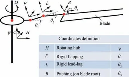
Fig. 1 Rigid coordinates definition for fully articulated hub.
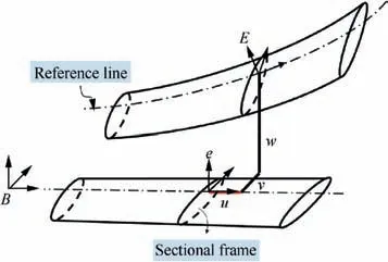
Fig. 2 Elastic coordinates definition for deformed blade.
here,u,v,and w denote to elastic deformations of the reference cross-section while x is the coordinate of the section in B.Based on relationship of the radius vector and curvilinear coordinates, we have:
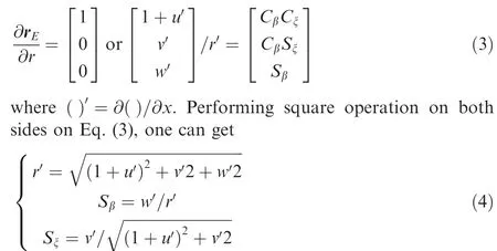
Derivatives of the angles ˙ξ, ˙β can be similarly deduced as functions of blade motions for later use.
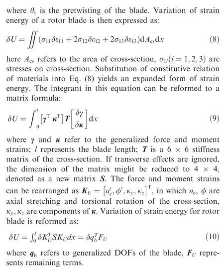
2.2. Blade strain energy
Strain energy of rotor blade based on GEBT can be found in many literatures.Here we just rebuild the basic formulas on new defined coordinate systems. The whole deduction generally starts from Green strain. Suppose A is a point in reference cross-section with coordinates (x, η, ζ), position vectors of A in B system under undeformed and deformed cases are:
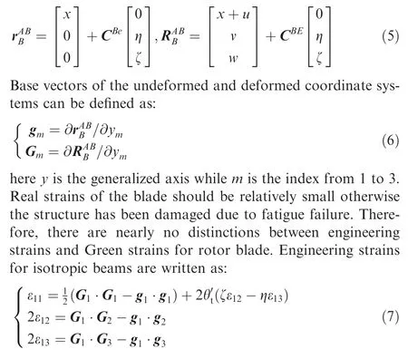
2.3. Blade kinetic energy
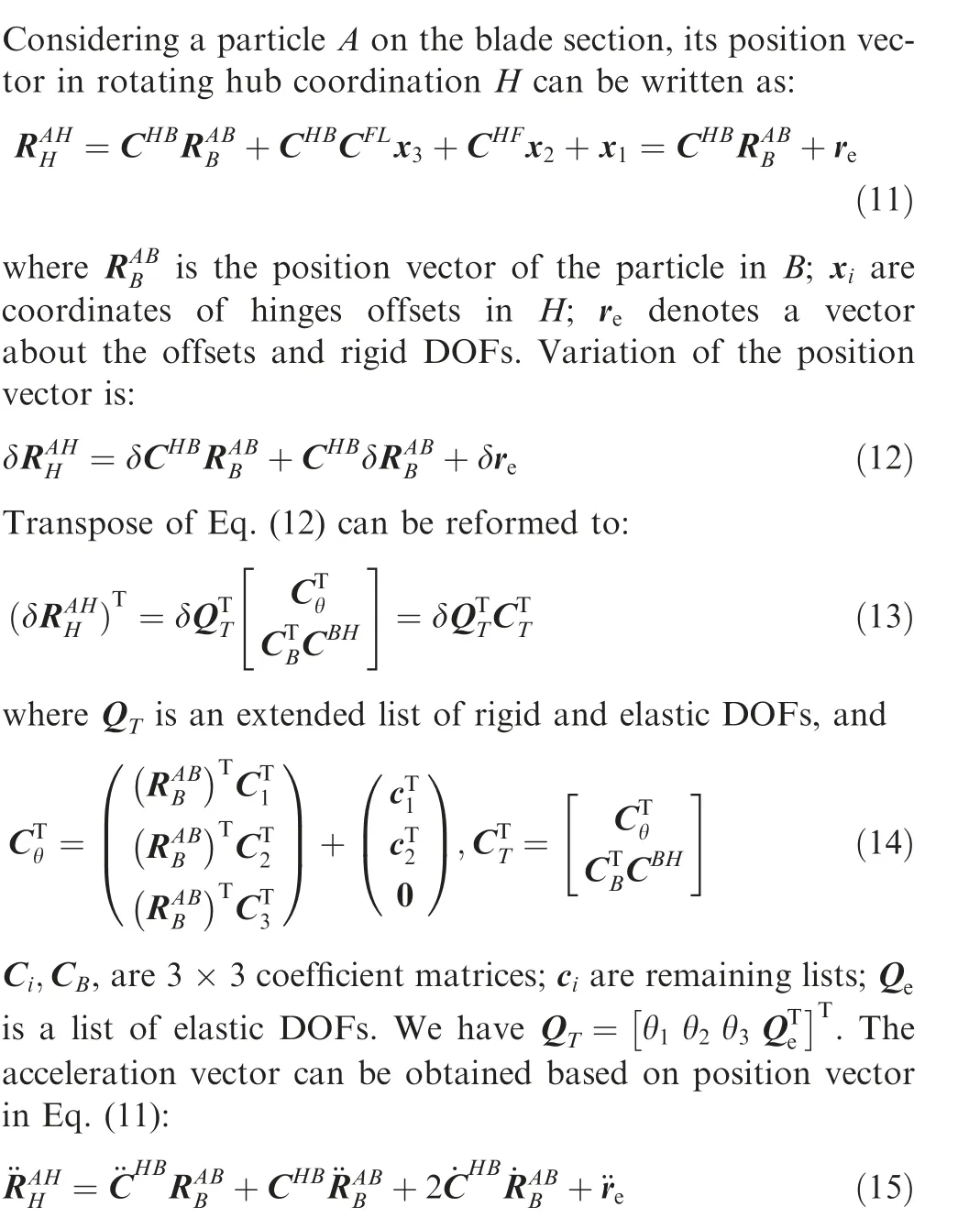
Suppose the rotation vector of the hub in inertia coordinate system is ω, absolute acceleration vector in H is developed as follows:
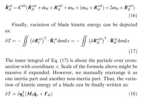
in which, Mis the global mass matrix of the blade and Fis the remaining non-inertia part.
2.4. Virtual work of external forces
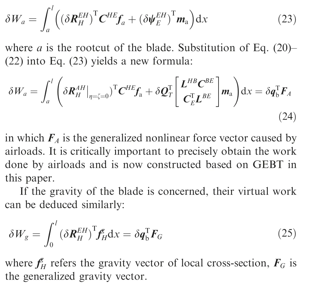
Aerodynamics of helicopter rotor system has been developed as a separate field from rotor dynamics. Basically, there exist three classifications: steady model, unsteady model,and CFD method.The focus is to obtain aerodynamic pressure around the blade and get airloads,including aerodynamic forces and moments. Gravity of the blade is essentially a kind of distributed force, which has more impact in static analysis than in dynamics.The work of airloads is commonly expressed in inertial system.Based on the definition of coordination systems before, we have two derivatives:
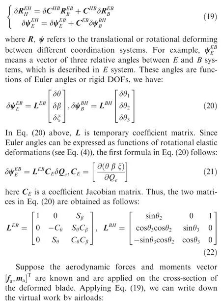
2.5. Governing equations
After variation of energy and virtual work of external forces are achieved, the dynamic equations can be developed based on Hamilton’s principle. Taking strain energy, kinetic energy and virtual work into the principle generates the final equation as follows:
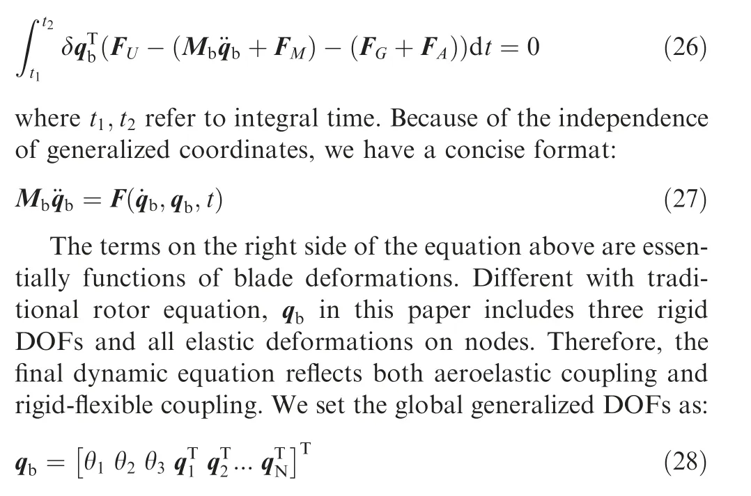
in which q(i=1,2,...,N)is the local generalized nodes for i-th element, N is the number of elements.
3. Solving static and dynamic problems
When static deformation tests are concerned,the equations for the rotor blade are simplified to F(q)=0. We use Newton iteration method to find the root of this nonlinear equation.The iterative formula can be expressed as follows:

where qis the i-th iterating response of q.Newton method is of second order precision. It is efficient and very common for the iteration to converge within several times. However, the large deforming case must be studied carefully. Because Newton method is very sensitive to the initial value, the iteration might be diverged with kind of unreasonable initial input.
In this paper, an asymptotic policy is introduced to solve static deformation of a beam. First, we take the external load as the maximum of a sequence of loads, in which differences between two adjacent elements in the sequence should be small. Second, the deformation under one specific load can be obtained via Eq. (29). The initial value of the equation for next load should be set to the previous deformation. It is critical for Newton iteration to minimize the gap between the initial value and the real root. At last, the final response can be obtained asymptotically under the external load.
In order to get dynamic response,implicit trapezoidal integration method is adapted to solve the rotor equations.Besides,we use Newton iteration to solve the subsequent nonlinear equation derived on each integrating step. Mass matrix is analytically derived from the formulation while stiffness matrix is numerically obtained by the central difference method.
3.1.Deflections and natural frequencies of the‘‘Princeton beam”
Princeton beam experimentis very famous and often used to verify nonlinear structural model. The beam with length of 0.508 m(20 in)is selected,undergoing deformations in various directions with different pitch angles (0-90°) and different tip loads (0.45 kg, 0.90 kg, and 1.35 kg). Properties of uniformed cross-sections used in this paper can be found in Ref.30.In the experiment, the cylinder-shaped tip weight on Princeton beam was not described specifically.Without the mass,we evaluated its inertial terms based on the estimated sizes and density of the beam.Note that the gravity of the beam must be concerned for verification. It is being modeled as a spanwise uniformly distributed force. Now using the new rigid-flexible model, we can obtain the static deflections and first few natural frequencies of flapping and lead-lag.
Deforming at the tip of the beam by this paper is shown in Fig. 3. As seen in this figure, most of simulating results are in good agreement with the experimental data. Note that definitions of‘‘flap” and‘‘lead-lag”here are not the same as in previous section of this paper. When the pitch angle is 0 or 90°,either flap or lead-lag reaches the maximum while other two DOFs stay untouched. That means no coupling issue for this case.When the pitch angle changes,deformations will be coupled with each other, especially for flapwise and twisting DOFs. The tip twisting response is determined by the projection of the elastic axis and leading edge of the cross-section on a plane perpendicular to the undeformed cross-section(Fig. 4). According to the nonlinear geometric relationship,we have:

Here, β, ξ are Euler rotations of the deformed cross-section.The equation above shows that geometric twisting was entirely generated by bending deflections.
The maximum of flapping among all cases exceeds 0.3(nondimensionalized), which means the beam suffers large deflection under 1.35 kg tip load. Limited to moderate deformation hypothesis, the classical structural modelcannot catch the structurally coupled characteristics, as in Fig.5.In fact,bending deflection will make the beam a bit stiff.Thus,it seems logical for the classical model to underpredict the natural frequencies. Meanwhile, our rigid-flexible model gives the similar results with RCAS software.In short,new structural model based on geometrically exact formulae is capable for static response and natural frequencies of largely deformed beams.
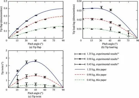
Fig. 3 Deflections of Princeton beam under different pitch angles.
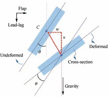
Fig. 4 Coupling effect between bending and twist of crosssection (φ is totally produced by flap (w) and lead-lag (v).)
3.2. Rotor blade droop stop impact
To verify the new rigid-flexible rotor dynamic model,we introduce an experiment of blade droop stop impact. Keller conducted the test of the blade droop stop impact with a 1/8 scaled H-46 helicopter blade.The configuration of the experiment is shown in Fig. 6.There are flap hinge and a droop stop unit installed near the root. In initial state, the hinge was blocked and the blade bended due to its Gravity and the accelerometer on the tip. The support device was suddenly released, the blade rotated downward consequently. When the flap hinge angle reached zero degree, the blade contacted the stop equipment and then rebounded off. Keller recorded the data up to 0.5 s, covering the main stages of droop stop impact test.The test gave out 3 kinds of data:flap hinge angle,blade tip deflection,and strains on the specific locations.Structural properties can be found in Ref. 34.
In simulation, the blade can be modelled as a preconed beam hinged on the hub.The test of the largest preconed angle 9.7° is selected in this paper. We carry out the simulation in two stages.The static bending analysis under the Gravity load comes first. Since the hinge was blocked, the blade near the root must be fixed.Deflections including bending and rotation of all nodes in finite element are used as initial conditions for the second stage of dynamic simulation. In the second stage,the flap hinge becomes free and the simulation switches to hinged mode.In the process of impact,a hinge spring is introduced to model the droop stop. Stiffness of the hinge spring was missing in original experiment report. Based on the test data of hinge angle which includes obvious negative values on impact, we set the stiffness to 2 × 10N·m/rad in simulation.
Fig. 7 gives the time history of flap hinge angles from the test and simulations.Ref.33 used the rigid-flexible rotor model based on moderate deformation beam theory, short for ‘‘classical model”.As in this figure, the process of impact predicted by the new model sustains from 0.13 s to 0.36 s. Before the impact, the hinge angle contains a section of nonlinear setbacks, which indicates the coupling between rigid and flexible deformations. Results before impact and on impact are more consistent than these after impact. After impact, the experimental time lag between test data and analysis prediction exists. The lag might be caused by the testing equipment, as explained in the Ref. 32. If the phase of hinge angle after impact is fixed up,the current agreement would be better than the referenced results.
Tip displacement of the Keller blade dropped from 9.7° is drawn in Fig. 8(a). It is composed of flap rotation movement and the elastic deformation of the tip. Much like the upward movement of the flap hinge angle, the upward motion of the blade tip at t = 0.04 s is caused by the flexing of the blade while falling. In general, the result predicted by this paper keeps much consistent with the experiment data and the agreement shows better than the classical model. The maximum deformation exceeds 15%of the blade length,which probably leads to the minor difference between experiment data and prediction of the classical model.In the process of the impact,the tip displacement approximately equals to the elastic component since hinge angle is reaching zero degree.
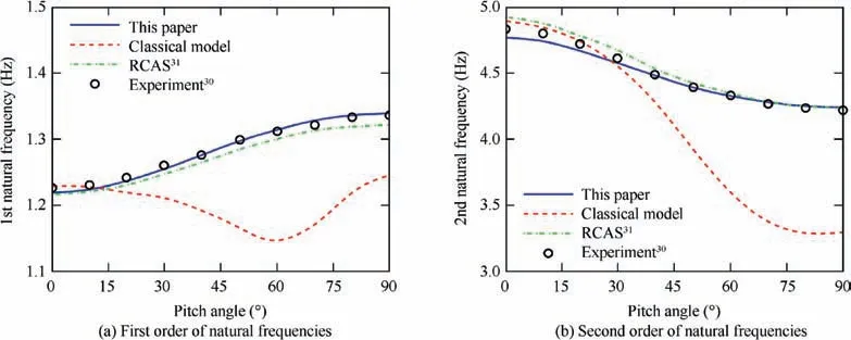
Fig.5 Natural frequencies of Princeton beam under different pitch angles(‘‘Classical model”are based on moderately deformed beam theory15.)
In Fig. 8(b) compares the strain at 20%R of the Keller blade by the test and analysis prediction. The time lag also exists after the impact.Result from the current model contains higher order components than the classical model.It should be caused by the ODE solver used in this paper. We applied the implicit trapezoidal integration method to solve the final rotor equations. This method does not introduce any numerical damping on time marching.
3.3. Dynamic problems with rotating frame
The following simulation is carried out to verify the new model for dynamic response problems. The example beam is taken from the Ref. 36. It is a simple uniform beam of length 1 m with vertical tip load under non-rotating and rotating conditions.We select two dynamic cases(different boundary conditions) to verify the model. The selected cases are listed in Table 1.
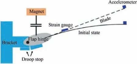
Fig. 6 Test configuration of Keller droop stop impact.33
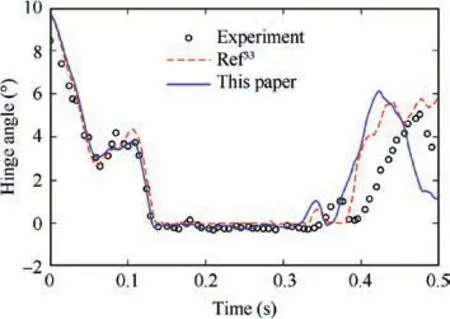
Fig. 7 Hinge angle of Keller blade when dropped from 9.7°.
Fig. 9 gives the rigid components in the tip response of the rotating cantilevered beam. Both results from DYMORE and this paper are matched very well.In response of twist,we have more components of high frequencies in the results. This is likely because DYMORE used energy decaying scheme to solve the dynamic equation of nonlinear beam models.The scheme consumes energy on each step to survive the numerical integration method, which will remove the high frequency components and smoothen the curve of the response.
In Case 6,both offsets of flap and lead-lag hinges are set to 0.1. The in-plane dynamic force will cause the beam to bend and rotate in lead-lag direction. The lead-lag time history is plotted in Fig.10.In this figure,lead-lag refers to the total displacement in rotating coordination B and its rotation is exactly equivalent to the rigid lead-lag defined in this paper.Curves of lead-lag vand lead-lag rotation θhave a same frequency of vibration because of the relationship v=v+sinθ, in which vrefers to small elastic lead-lag.We also can see the axial displacement contains higher frequencies than DYMORE. It is reasonable since the natural frequency of axial stretching(561 Hz) is much higher than that of lead-lag (4.3 Hz). All response simulation proves that the new model can accurately capture coupling effect between elastic deformations.

Table 1 Conditions of dynamic test cases in Ref. 36.
4. Structural coupling characteristics of rotor blade
Obtaining natural frequencies of a blade is equivalent to solve the generalized eigenvalues problem of the characteristic matrix Mb K. For one normal mode, elastic DOFs may be coupled with each other.we introduce a new factor to quantify the coupling characteristics,which should be a ratio of vectors.According to division operation of two arbitrary vectors and coupling factor defined in electromagnetics, we propose a new factor between two components a and b in one mode as:
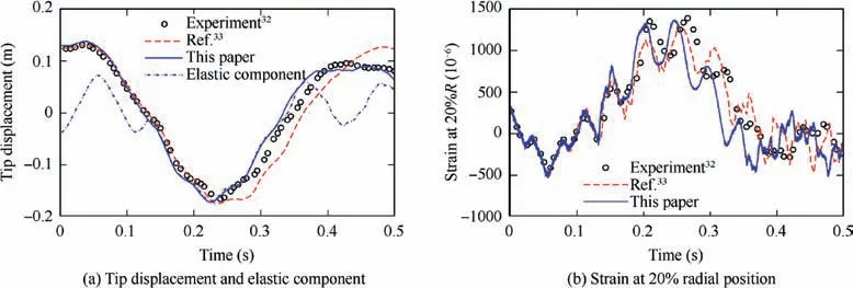
Fig.8 Tip displacement (a) and strain at 20%R(b) of Keller blade when dropped from 9.7° (‘‘R” refers to the radial position of blade tip.)
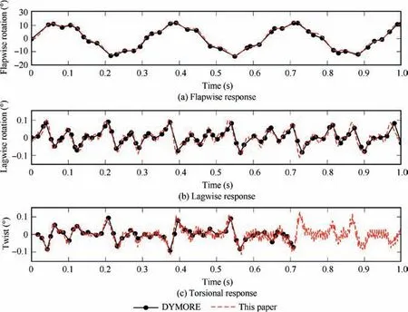
Fig. 9 Tip rotations of the rotating beam, Case 5.
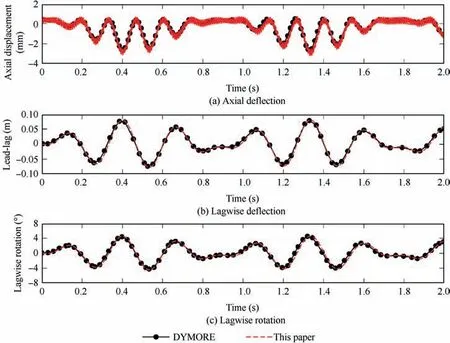
Fig. 10 Tip response of the rotating beam, Case 6.

Here,we use β to indicate the coupling strength,β ∈[0,1 ].The larger the value, the more coupling the two modal components. For example, β = 0 means they are independent and 1 means fully coupled. In practice, we set one component of modal shapes to the principal to study the coupling characteristics.
4.1. Coupling characteristics of fully articulated blade
SA349/2 is a light-weight helicopter with fully articulated rotor hub. The blade has length of 5.25 m. To avoid ground resonance, a nonlinear lead-lag damper was installed on the hub.Structural properties of its rotor system are taken from the Ref. 38.
On mode identification,it is necessary to identify the mode type based on mode shapes, which might be coupled in higher order of modes. Since the rigid-flexible model have three rotational DOFs involved in final dynamic equations,eigenvectors must be transformed to hub rotating coordinates. Both conditions make the mode identification more difficult than usual.Taking the working speed condition as an example, the 3-8th mode shapes are shown in Fig.11.Clearly,in 3rd mode,mode shapes of flap and twist are coupled with each other.Based on the feature of principal mode, the No.3 mode is identified as the 2nd flap mode. The No.4 mode should be the 1st twist mode. The No.5 mode is the 3rd flap mode since the flap deflection curve has two nodes. And the No.6 mode is recognized as the 1st lead-lag mode. We can also find that in mode No.7 and No.8, flap and twist modes are more strongly coupled than in previous modes. This phenomenon might be caused by the fact that the cross-section of a typical rotor blade is built as airfoil.
Table 2 gives all first 8 identified modes and the coupling factors between the principal component and other component. In this table, ‘L’ used in the legend refers to lead-lag mode,‘F’to flapping mode,and‘T’to twisting mode.The prefix number represents the mode order in corresponding mode.Besides, p refers to the principal mode with specific modal order. For the 1st modal order, we have identified the mode as the 1st lead-lag mode in Table 2,then p is alias of v.In this case, β= β= 0.0018. When the order rises, p changes accordingly. Therefore, values in cells of principal mode are definitively 1.0000, which indicates the mode is fully coupled with itself.As seen in Table 2,β=0.5601 is one of the highest factors. The virtual explanation of this coupling characteristics between flap and twisting was also shown in Fig. 11(Mode No.8). It shows the definition of coupling factor between elastic DOFs is reasonable and there is strong coupling phenomenon in rotor blade dynamics.
4.2. Coupling characteristics of hingeless blade
BO105 is a military helicopter with hingeless rotor hub. The rigid-flexible structural model developed in this paper is used to perform the mode analysis on this blade. For this type of rotor hub, there are no global flap and lead-lag rotations.We can set θ=θ=0 and trim off these two DOFs in structural modeling for hingeless hubs. Properties of BO105 rotor blade are referenced from the Ref. 39. The blade has length of 4.91 m with preconed angle 2.5° and linearly pretwist angle-8°. The rotating speed at work is designed to 424 r/min. We discretized the blade into 8 elements based on structural characteristics in finite element modeling.
To investigate the coupling characteristics, we plot the 3-8th modal shapes in Fig.12 and list coupling factors in Table 3.As seen in Fig. 12, principal modes of BO105 blade are much clear and easier to be identified because the highest coupling factor is about 0.1712 (Table 3), which is much less than the one for SA349/2. Generally, coupling feature of BO105 seems not that obvious as of SA349/2.But the most structurally coupled phenomenon still happens between flapwise and torsional DOFs. In addition, the axial deflection u shows independent for both rotor blades probably because the axial stiffness is much higher than bending or torsional stiffness.
4.3. Research on coupling characteristics of different rotor blades
To verify the new structural model and further present the mode-coupling feature of rotor blade, we study the relationship between natural frequencies and rotating speed to simulate start-up process of helicopter. In Fig. 13(a), we compare the SA349/2 simulating results with CAMRAD software,a sophisticated comprehensive analysis platform in helicopter research. The vertical line in this figure indicates the nominal rotating speed of the rotor (about 387 r/min). The 3rd flap mode and the 1st twist mode are coupled in between 300 and 350 r/min. Natural frequencies of the 1st twist mode go up rapidly as rotating speed increases. This means centrifugal forces should produce a powerful effect on twisting mode.
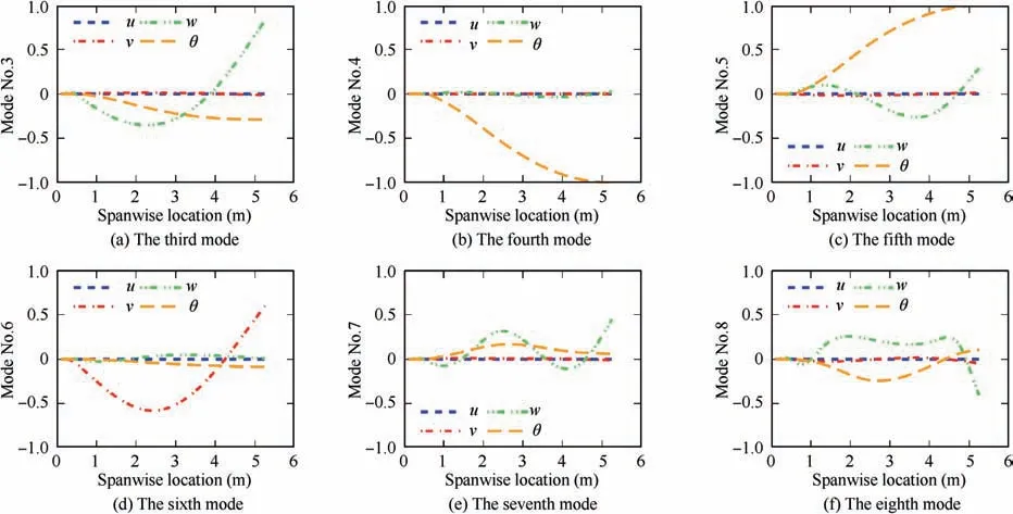
Fig. 11 Normalized mode shapes of SA349/2 rotor blade under working speed (3-8 modes) (The symbol ‘‘θ” refers to torsional deflection.)

Table 2 Identified modes and coupling factors between elastic DOFs on each mode of SA349/2 blade (Suppose ‘‘p” is the principal mode.) (‘1L’ refers to the first lead-lag mode, ‘1F’ to flap mode, and ‘1T’ to twist mode, etc.).
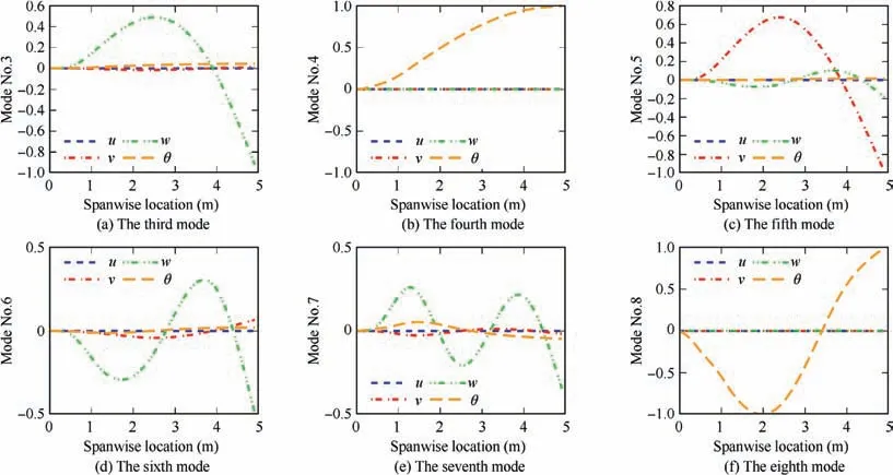
Fig. 12 Normalized mode shapes of BO105 rotor blade under working condition.

Table 3 Identified modes and coupling factors between elastic DOFs on each mode of BO105 blade.
We also plot the natural frequencies of BO105 rotor blade calculated using the new model in Fig. 13(b). At the working speed, results from CAMRAD IIare also drawn as a reference in this figure. For all lower modes up to the 7th mode,the maximum of relative difference between this paper and CAMRAD II is about 4.36%. It is shown again that the new structural model is highly capable of predicting natural frequencies of hingeless rotor blade.
To study the effects of centrifugal forces on structurally coupling characteristics, we preset a list of rotor speeds in the dynamic model and do modal analysis of the blade for each speed.The first 8 orders of modal shapes are selected to calculate coupling factors. As in Fig. 14, there are 8 points at each speed for both rotor blades. All points of SA349/2 are widely scattered on the graph while most points of BO105 are crowded under the line of 0.2. From a statistical perspective,coupling effects on fully hinged rotor (SA349/2) are likely much stronger than those on hingeless rotor (BO105).
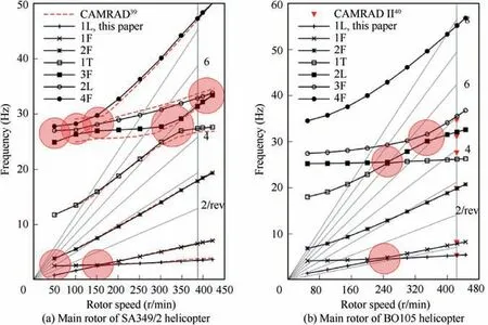
Fig. 13 Natural frequencies of SA349/2 (a) and BO105 (b) rotor blades under different rotating speeds (Areas where frequencies are close to each other are marked in red circle.)
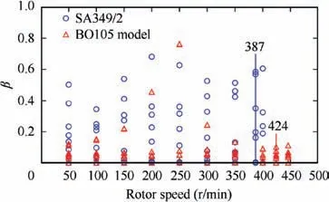
Fig. 14 Coupling factors of SA349/2 and BO105 rotor blade under different rotor speeds (Working speed: 387 r/min for SA349/2 and 424 r/min for BO105).
In addition, the most powerful coupling effect on BO105 happens in about 200-300 r/min section. In Fig. 13(b), we can see that resonance frequencies of flap are very close to these of lead-lag and twisting in this section(marked in red circle).Specifically,frequency of‘1F’at 250 r/min is very close to‘1L’ and likewise ‘2L’ to ‘1T’ at the same speed. Similar phenomenon can be also found on articulated rotor blade. For SA349/2, many areas are marked as red circle in Fig. 13(a)since there are at least two frequencies closed to each other in the area. This should be the reason why coupling factors are scattered irregularly in Fig. 14. In summary, closeness of natural frequencies will probably generate coupled characteristics in rotor structure.
5. Conclusion
This paper developed a new rigid-flexible structural model based on geometrically exact beam formulation for rotor blade and proposed a new coupling factor about modal shapes to quantify the coupling strength of the blade between different DOFs in modal analysis.The model has been used to solve static or dynamic problems in rotor system, such as predicting large deformation of Princeton beam, modelling droop stop impact of Keller blade, and analyzing coupling feature in hinged and hingeless rotor blades with the new factor. Some interest conclusion can be made as follows:
(1) When elastic deformation exceeds about 15% of the beam length, the moderate deformation beam theory comes to its limit.In Princeton beam deflection example,differences of natural frequencies between experimental data and analysis prediction became remarkably large when the tip load increased and tip flap went over the ratio of the beam length. In the example of droop stop impact of Keller blade, GEBT performed better than moderate deformation beam theory when the elastic component of tip displacement was approaching 0.15 m.
(2) Closeness of natural frequencies likely indicates the coupling characteristics in beam structure. The closer the natural frequencies, the stronger the coupling between corresponding DOFs. We did model analysis on SA349/2 and BO105 rotor blades and found that coupling characteristics in SA349/2 rotor system shows more outstanding than that in BO105. And the reason is the number of areas where natural frequencies are close to each other on resonance plot of SA349/2 are much more than number of those areas on BO105.
The authors declare that they have no known competing financial interests or personal relationships that could have appeared to influence the work reported in this paper.
