Shape preserving topology optimization for structural radar cross section control
Fei CHEN,Jihong ZHU,b,*,Xinxin DU,Ruitong ZHANG,Weihong ZHANG
a State IJR Center of Aerospace Design and Additive Manufacturing, Northwestern Polytechnical University, Xi’an 710072, China
b MIIT Lab of Metal Additive Manufacturing and Innovative Design, Northwestern Polytechnical University, Xi’an 710072, China
KEYWORDS Adjoint method;Physical optics method;Radar cross section;Shape preserving design;Topology optimization
Abstract The purpose of this paper is to present a shape preserving topology optimization method to prevent the adverse effects of the mechanical deformation on the Radar Cross Section (RCS).The optimization will suppress the variation of RCS on the perfect conductor surface by structural design. On the one hand, the physical optics method is utilized to calculate the structural RCS,which is based on the surface displacement field obtained from the finite element analysis of the structure. The corresponding design sensitivities of topology optimization are derived analytically and solved by the adjoint method. On the other hand, the RCS variation and mechanical performance are taken into account simultaneously by extending a standard compliance-based topology optimization model.Two optimization formulations are discussed in an illustrative example,where the influences of upper limits of the compliance and the RCS variation are considered. Two more examples are further tested to show the ability and validity of the proposed optimization method.©2021 Chinese Society of Aeronautics and Astronautics.Production and hosting by Elsevier Ltd.This is an open access article under the CC BY-NC-ND license(http://creativecommons.org/licenses/by-nc-nd/4.0/).
1. Introduction
Topology optimizationhas been developed as an effective method of achieving the lightweight design and meeting multidisciplinary performance requirements.It has been extensively studiedin recent years and widely used in aerospace structures.
In the past decade, the electromagnetic performance of aerospace structures has become increasingly demanding,especially for the structures sensitive to their surface configuration (e.g. conformal antennasand reflector antennas, etc.).In these cases, the structural Radar Cross Section (RCS) will be significantly affected by the deformation under internal and external loads, which needs to be controlled carefully in the structural design process. Controlling structural RCS can be considered as a typical electromagnetic shape preserving problem,which means that the physical shape of the structure may be changed due to the deformation,but the RCS can still be consistent with that of the undeformed structure.
Existing shape preserving design is carried out using topology optimization to suppress adverse warping deformation in typical structural functional regions under pure mechanical loads or thermal-mechanical loads. Nevertheless, for RCS control,most of the current work has been focused on the direct physical shape design of reflect surface. For example,Bondeson et al.performed shape optimization based on the gradient method, which reduced the RCS of the perfect conductor through a small number of iterations. Dadash et al.developed the analytical adjoint sensitivity formula for the scattering parameters of the metal structure, which favored the finite-difference time-domain method and the method of moments.
In terms of the influence of the structural deformation on electrical performance, Zhang et al.studied the influence of random errors by deriving the sensitivities of electrical properties with respect to the nodal deformation on the structural surface. Hu et al.optimized the electrical performance of the reflector antennas under thermal loads using topology optimization and genetic algorithm. Similarly, Elfrgani and Reddyproposed a topology optimization model based on the global response surface method to enhance the structural RCS. Due to the lack of analytical sensitivity of RCS with respect to structural configuration parameters, the problems mentioned above are limited to using gradient-free algorithms.The complexity of optimization problems and the number of design variables are relatively small.
In this paper, we propose extending the standard compliance-based topology optimization model to the RCS shape preserving problem.The result of topology optimization design determines the surface displacement field of the structure.The coordinates of surface nodes are directly used to calculate the current RCS. Therefore, by deriving the analytical sensitivity of the RCS variation and structural compliance with respect to the topological design variables, the gradient-based algorithm will be utilized to optimize the structure,suppressing the local RCS variation and maintaining the structural stiffness simultaneously. The remainder of this paper is organized as follows. Section 2 introduces the problem definition, the physical optics method for RCS calculation, and optimization formulation. Section 3 derives the sensitivity of the RCS variation.Numerical examples are given in Section 4.The conclusions are outlined in Section 5.
2. RCS shape preserving problem and optimization formulation
Generally, the RCS shape preserving problem is illustrated in Fig. 1. E,Hand E,Hdenote the incident plane wave and the reflected wave, respectively. F is the external load. As illustrated in Fig.1(b),the structure consists of two layers.The upper layer Ωrepresents the non-designable domain, which includes the functional area.Ωis responsible for maintaining the physical shape and reflecting the incident wave. The RCS of the functional domain is the focus of concern and will be changed due to the external load F. The lower layer Ω represents the design domain of topology optimization, which is used to strengthen the structure. The RCS variation of the upper functional area will be suppressed due to the lower topology optimization design.Note that,to simplify the calculation model,the structural materials are all perfect electric conductors.
2.1. Physical optics method
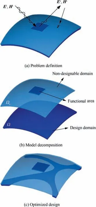
Fig. 1 Illustration of the RCS shape preserving problem.
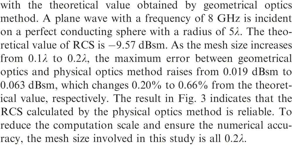
First of all,we should choose an appropriate method to calculate RCS for this study.At present,numerical methods(mainly including method of moments, finite-difference time-domain method, and finite element methodand high-frequency asymptotic methods are two types of widely used methods for the RCS calculation of complex objects. Numerical methods are known for the accuracy, but as the electrical size of the target increases, the cost of the calculation becomes unaffordable. On the contrary, the high-frequency asymptotic methods are suitable for the electromagnetic scattering problem of electrical large size targets. Since the electrical size of the structure involved in this paper is relatively large, and considering the simplicity of solving the sensitivity of topology optimization,the most commonly used physical optics method of the asymptotic methods is utilized to calculate the RCS of the target.
Here, we give a simple introduction to the physical optics method. More specific details can be found in Knott et al..In this section, the back scattered far fieldis formulated as

where j is the imaginary unit,k and η represent the wave number and characteristic impedance in the free space,respectively.r is the distance from the radar transmitter to the target. S is the objective surface for RCS calculation.J denotes the surface current.kis the unit incident wave vector.ris the coordinate vector of the center position of each small integral region S.Direct discretization, Gaussian discretization, and Gordon discretization are three widely used ways to approximate the integration Eq. (1). For simplicity in programming, we will here use the direct discretization.Eq.(1)can thus be written as
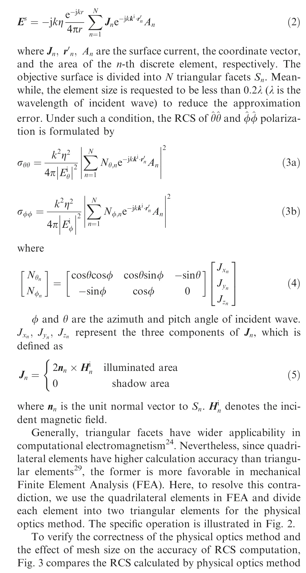

Fig. 2 Difference of elements between FEA and physical optics method.
2.2. Optimization formulation
The definition of RCS shape preserving problem is illustrated in Fig.1.To suppress the RCS variation,a new topology optimization model is given here.First of all,the RCS variation of the deformation process is defined as follows:
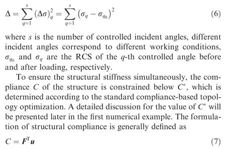
where F and u denote the external loads and the global displacement vector, respectively.
The mathematical formulation of topology optimization is given as follows:find:

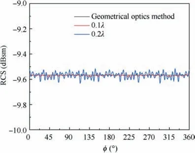
Fig. 3 RCS of a perfect conducting sphere obtained by the geometrical optics and physical optics method.
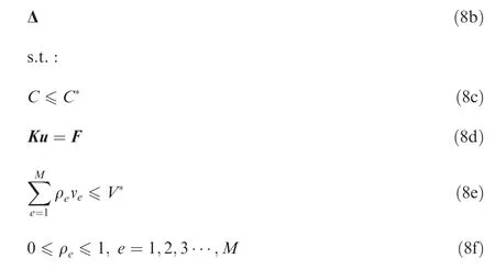
where ρ represents the pseudo-densities of topology optimization, K is the global stiffness matrix, the design domain is divided into M elements,vand Vdenote the e-th element volume and the prescribed volume upper limit, respectively, ρis the pseudo-density of the e-th element.
In this paper, we adopted the modified Solid Isotropic Material with Penalization (SIMP) interpolation modelto relate the Young’s modulus and the pseudo-density, which is formulated as

where Edenote the penalized Young’s modulus,Eand Eare the Young’s modulus of the solid and void material, respectively. Ein this study is non-zero to prevent the stiffness matrix from becoming singular (here, E=1×10E). p is the penalty factor of the interpolation model.
3. Sensitivity analysis
Fig. 4 illustrates the relationship that how the topological design variables are related to the RCS. To utilize the gradient-based algorithm, the sensitivity of the RCS variation Δ with respect to the design variables will be derived in detail.The sensitivities of the volume constraint and the structural compliance can be easily found in other structural optimization articles. The detailed derivations are thus not provided here.
In the present work,the ^φ^φ polarization is utilized to illustrate the effectiveness of the RCS shape preserving method.Therefore, the expression of RCS in the following is based on Eq. (3b).
Based on the chain rule,

To compute ∂σ/∂ρ, Eq. (3b) is simplified as follows:
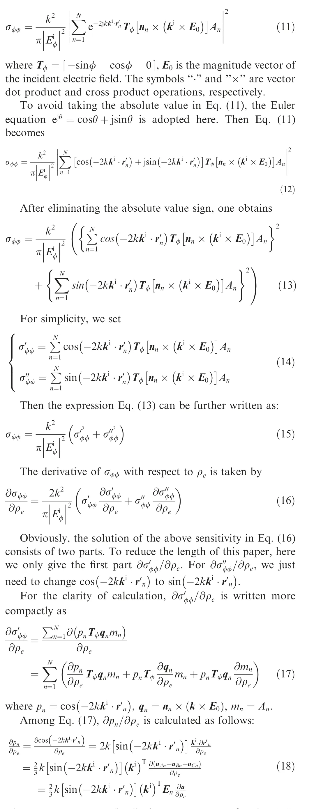

Fig.4 Relationship between topological design variables and the RCS.
where u,u,uare the displacement vectors of nodes A,B,C of the n-th triangular element, respectively, u is the global
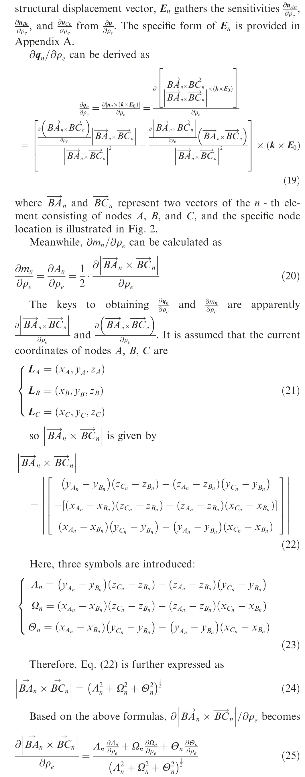
Among others, ∂Λ/∂ρcan be calculated as follows:
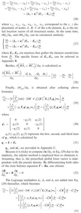
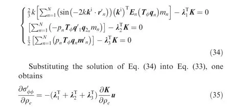
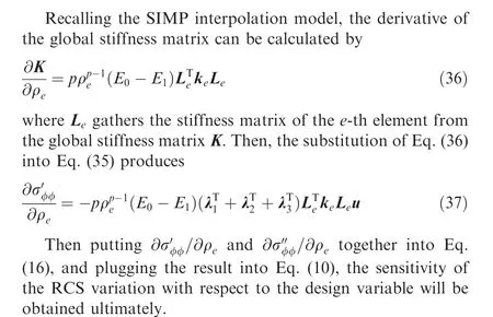
Because of the arbitrariness of Lagrange multipliers, there always exist λ, λand λthat make
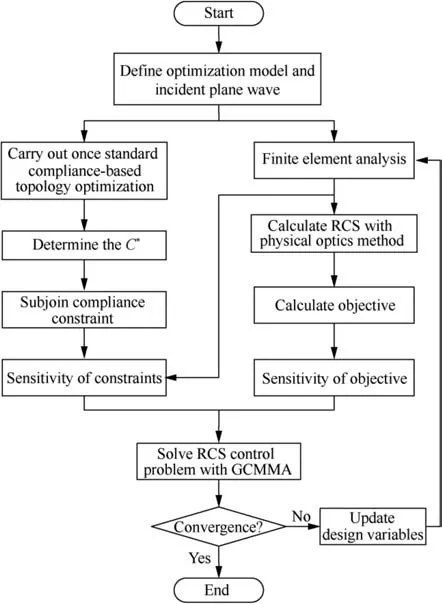
Fig. 5 Flow chart of topology optimization of RCS shape preserving problem.
4. Numerical implementations
In this section, the first example is utilized to explore the nature of the RCS shape preserving problem. The other two examples demonstrate the validity of the RCS shape preserving method.The Globally Convergent Method of Moving Asymptotes (GCMMA)is applied to update the design variables over the whole optimization. Note that the ill-posed optimization problem in Eq. (8d) will also be well-handled by the GCMMA algorithm without the relaxation of restriction methods. Meanwhile, the criterion of optimization convergence is that the variation of the current and next iteration does not exceed 0.01%.With the filter radius being three times the average element size, both the sensitivities of RCS variation and structural compliance with respect to the pseudodensity are filtered by the filtering mechanismto deal with the checkerboard phenomenon in topology optimization. In addition, to ensure the effectiveness of the physical optics method,the electrical size of the RCS control domain involved in this paper are all more than 10 times of the corresponding incident wavelength λ. The mechanical models are established and analyzed by ANSYS Parametric Design Language(APDL) in ANSYS. The RCS calculations are finished based on C language.The flow chart of the proposed RCS shape preserving method is illustrated in Fig. 5.
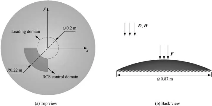
Fig. 6 A sphere PEC shell with a quarter ring for RCS shape preserving.
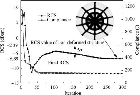
Fig.7 Optimized result and convergence history of the standard topology optimization.
4.1. RCS shape preserving for a sphere shell
A sphere shell of the Perfect Electric Conductor (PEC) is presented in this section.The geometrical size and boundary conditions are listed in Fig. 6. The plane wave (θ=0,φ=0)with a frequency of 10 GHz (λ=0.03 m) propagates in the negative direction along the z axis. The Young’s modulus and Poisson’s ratio for the model are 70 GPa and 0.33,respectively. There is an upper layer defined as the non-designable domain where the element size is identical to the design domain of the lower layer. The thickness of the two layers is 2 mm for the design domain and 0.01 mm for the nondesignable domain,respectively. All the shell elements are offset from the midplane by half of the corresponding thickness.Since the meshes of each layer are identical,nodes of each layer are correspondingly merged together. The design domain of the model is discretized into 18768 shell elements with the mesh size 0.2λ.A 31230 N force F is uniformly applied to 1041 nodes of the loading domain. The RCS of the initial undeformed structure calculated by the physical optics method is -2.39 dBsm.For verifying the effectiveness of physical optics method in this model, the RCS is calculated again by the method of moments, which is -2.41 dBsm.
First of all, the standard compliance-based topology optimization with the 40% volume fraction for the sphere shell is given for comparison.The optimized result and convergence history are shown in Fig.7.Although the ultimate compliance sharply decreases to 153.49 J, the final RCS of the shape preserving domain is-6.89 dBsm,where the RCS variation Δσ is 4.50 dBsm.
When suppressing the RCS variation, the stiffness of the structure must be considered. There are two options for the optimization formulation of this problem. The first choice is minimizing the structural compliance and constraining the RCS variation. The other option is minimizing the RCS variation and setting a structural compliance constraint.


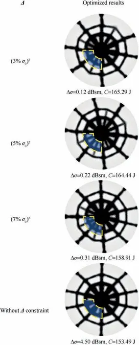
Fig. 8 Optimized results under three RCS variation constraints.
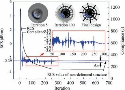
Fig. 9 Iterative process of optimized result of the optimization.

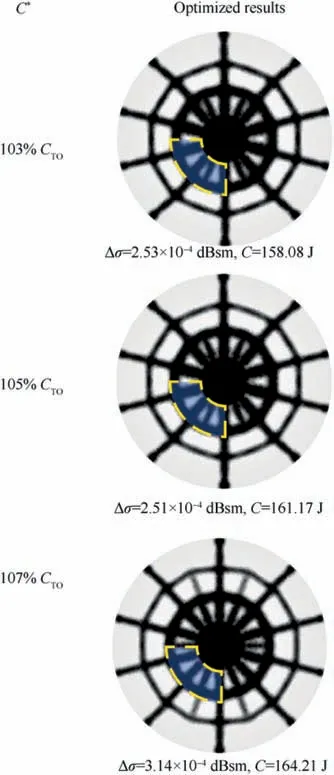
Fig. 10 Optimized results under three compliance constraints.

Then,the optimization is carried out based on the formulation Eq.(8d),with RCS variation and structural compliance as the objective and the constraint.The constraints of compliance Care set to 103% C,105% C,and 107% C,where Cis the optimized compliance of the standard topology optimization. The comparison of the optimized results is shown in Fig.10.All the compliance constraints are basically satisfied during the optimization. At the same time, the results of RCS values are well-controlled and consistent with the value of the undeformed structure. Fig. 11 shows the convergence history of the objective and the compliance when the constraint is 105% C. Unlike the oscillations shown in Fig. 9, the objective in Fig.11 only fluctuates slightly.This is because when setting a compliance constraint, the optimization algorithm will first seek to satisfy the compliance constraint. The structure already has a very stable topological configuration when the compliance constraint is satisfied.At that moment,minimizing the objective will not lead to significant changes in compliance.Therefore, the algorithm will continue to minimize the objective instead of oscillating between satisfying the constraint and minimizing the objective.
Comparing the third result in Fig.8 and the second result in Fig.10,the RCS control effect of the latter is better under the nearly same compliance value. Moreover, because it is challenging to meet the constraint of RCS variation quickly and stably for the ill-posed problem, the first optimization formulation is time consuming.Therefore,it is better to set the RCS variation as the objective for the RCS shape preserving problem.
4.2. A rectangular PEC plate with a serrated RCS shape preserving domain
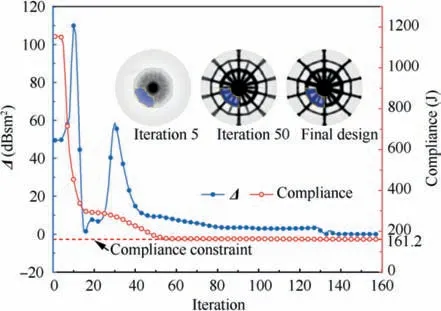
Fig. 11 Iterative process of optimized result of optimization when considering RCS variation and structural compliance as objective and constraint.
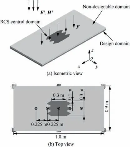
Fig. 12 A rectangular PEC plate with a serrated RCS shape preserving domain.
In this section, a rectangular PEC plate with a serrated RCS shape preserving domain is optimized. As shown in Fig. 12,a 10 GHz plane wave (θ=0,φ=0) propagates in the - z direction. The RCS value obtained by the physical optics method for the undeformed serrated domain is 22.739 dBsm.For comparison, the RCS calculated by the method of moments is 22.712 dBsm.The thickness of the upper layer and the second layer is 1 mm and 5 mm, respectively. The each layer of this structure is discretized into 45192 shell elements with mesh size 0.2λ.Five 600 N forces are applied to the structure. The same material as the first example is utilized here,and other boundary conditions are shown in the second graph of Fig. 12.
The standard topology optimization is first carried out to determine C.The RCS and compliance of the optimized result are 21.798 dBsm and 32.463 J (C). Here, the compliance constraint Cis set to 103% C, i.e., 33.437 J. At the same time, different volume fractions are adopted to observe how the difference between the current optimization and the standard topology optimized results changes. Note that the corresponding Cand Calso change accordingly.
Fig. 13 illustrates the results of the three volume fractions and compares the results of the RCS shape preserving method and the standard topology optimization.To minimize the RCS variation, the material in the center of the plate tends to distribute laterally to occupy the serrated domain. When the volume fractions are set to 30%, 35%, and 40%, the RCS variation by the shape preserving method decreases by 49.55%, 42.08%, and 38.62% compared with the compliance optimization.It shows that the proposed method is more effective for the RCS control when the amount of material is less.
Furthermore, the results of three compliance constraints are compared to demonstrate the stability of the RCS shape preserving method. In order to ensure that the structural stiffness will not be lost too much compared with the standard compliance-based optimization, the compliance constraints are set to 101% C, 102% C, and 103% C, respectively.The volume fractions are all 35%. The results are illustrated in Fig.14.With the constraint value increasing,the RCS variation of the optimized result decreased by 28.16%, 36.56%,and 42.08% compared with the corresponding standard optimization. Fig. 15 shows the displacement fields of the RCS control domain under the compliance-based design and three RCS shape preserving designs. It can be seen that the result of RCS shape preserving design is more uniform in lateral displacement distribution than compliance-based design, which means that the optimized results tend to maintain the physical shape of the RCS control domain in the lateral direction.When the volume fraction is 35% and the compliance constraint is 102% C, the convergence history of the objective and compliance constraint is shown in Fig. 16.
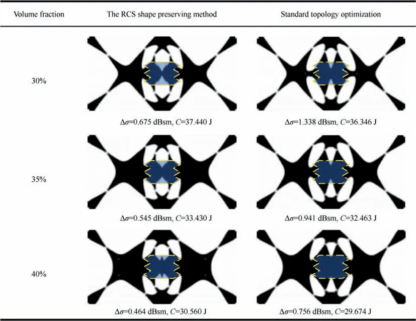
Fig. 13 Results of RCS shape preserving optimization and standard topology optimization in three different volume fractions.
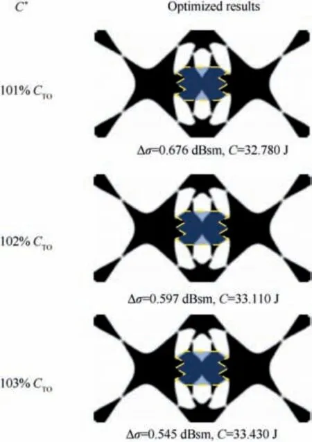
Fig. 14 Optimized results under three compliance constraints.
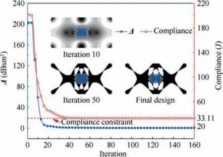
Fig. 16 Iterative history of optimized result of optimization.
4.3. A complex structure with an RCS shape preserving domain
The RCS shape preserving of a complex structure is presented in this section.The thickness of inner layer and outer layer are 5 mm and 0.01 mm, respectively. As shown in Fig. 17, the outer layer is divided into the RCS control domain (the dark gray part) and general domain (the light gray part). They are discretized into 1156 and 39832 shell elements, respectively.The material property is identical to that used in the last section. The model is fixed at where x=1.0 m. The structure is subjected to aerodynamic loads that have been transformed into the section loads. The specific load value is shown in Table 1. A 10 GHz plane wave (φ=0) propagates along the xoz plane as shown in Fig.17.The RCS variations in three different incident angles, i.e., θ=0,15, and 30, are taken into account simultaneously. The initial RCS calculated by the physical optics method is given in Table 2. To verify the effectiveness of RCS computation, the RCS obtained by method of moments are also shown in Table 2.
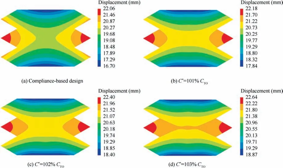
Fig. 15 Displacement fields for RCS control domain of compliance-based design and RCS shape preserving design.

Fig. 17 Geometrical model and boundary conditions.

Table 1 Section loads of structure.

Table 2 RCS calculated by method of moments and physical optics method.
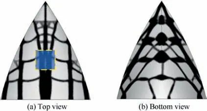
Fig. 18 Optimized results of standard compliance-based topology optimization.
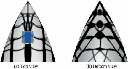
Fig. 19 Optimized results of RCS shape preserving optimization.
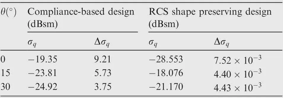
Table 3 RCS variation of standard topology optimization and RCS shape preserving optimization for three angles.
The standard compliance-based topology optimization design with the 40%volume fraction is shown in Fig.18.Then,the compliance constraint Cis set to 103% C(i.e.,1133.98 J) in the current RCS shape preserving problem. The final optimized result of RCS shape preserving is shown in Fig. 19. Table 3 illustrates that the RCS variations decrease sharply compared with the standard topology optimization.The RCS value is basically the same as that of the initial undeformed structure. Fig. 20 shows that, by changing the loadcarrying path,the displacement distribution of RCS preserving domain are more uniform than the compliance-based method.The above results indicate that the proposed RCS shape preserving method is effective for decreasing RCS variation.The convergence history of the objective Δ and compliance is illustrated in Fig. 21.
5. Conclusions
In this paper,we proposed a shape preserving method to minimize the RCS variation for PEC structure when subjected to mechanical loads. By the physical optics method, the RCS of electrical large size structures can be calculated efficiently.Meanwhile,we presented the analytical sensitivities of the RCS variation with respect to the topology variables.
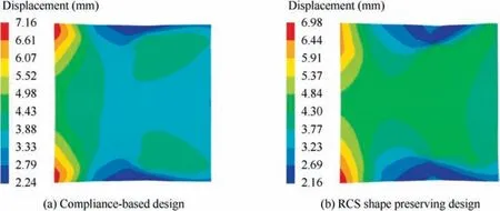
Fig. 20 Displacement fields for RCS control domain of compliance-based design and RCS shape preserving design.
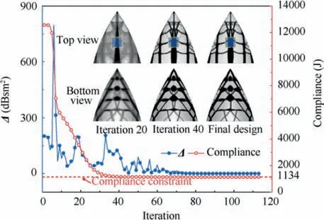
Fig. 21 Iterative process of the optimized result of the optimization.
The illustrative example showed that the optimization could converge in fewer iteration steps and obtain a better shape preserving result when utilizing the RCS variation as the objective and the structural compliance as the constraint.Based on the determined optimization formulation,the results of two more examples indicated that the RCS variation could be significantly suppressed by changing the load-carrying path.Moreover, the less the amount of material used in the structure, the better the proposed RCS shape preserving method compared with the standard topology optimization. Finally,there is a trade-off relationship between the RCS shape preserving and the structural compliance in the optimization process. The value of the compliance constraint should be determined according to the specific problem.For future practical applications, we only need to replace PEC materials with specific materials and improve the corresponding algorithms.
The authors declare that they have no known competing financial interests or personal relationships that could have appeared to influence the work reported in this paper.
This work is supported by Key Project of NSFC (51790171,51761145111, 51735005) and NSFC for Excellent Young Scholars (11722219).
Appendix A. The matrix Eof Eq. (18)
Eis a matrix sized 3×dofs, where dofs is the structural degrees of freedom.The following three parts of Eq.(A1)correspond to the nodes A, B, and C, respectively. The specific form of Eis as follows:

Appendix B. The matrices E-Eof Eq. (26) and Eq. (27)
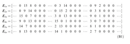
The dimensions of E-Eare all dofs×dofs. The Eq. (B1) is not the specific mathematical formula but a form that shows readers how to assemble the matrices. The numbers in E-Erepresent the sequence of the figure‘‘1”at each column in the case that if we take the corresponding rows and columns out separately, and the other elements of E-Eare ‘‘0”.
Appendix C. The matrices qand mof Eq. (29)
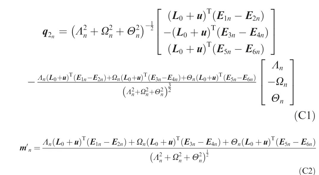
The specific forms of qand mare as follows:
 Chinese Journal of Aeronautics2022年6期
- Chinese Journal of Aeronautics的其它文章
- Experimental investigation of a gliding discharge plasma jet igniter
- Evolution of turbulent boundary layer over a three-dimensional bump
- Conceptual design and preliminary experiment of icing risk management and protection system
- Direct thrust control for multivariable turbofan engine based on affine linear parameter-varying approach
- Characteristics of reattached boundary layer in shock wave and turbulent boundary layer interaction
- Structurally coupled characteristics of rotor blade using new rigid-flexible dynamic model based on geometrically exact formulation
