Calibration method of quartz accelerometer on dynamic centrifuge
Yingbo SUN, Shunqing REN, Changhong WANG
School of Astronautics, Harbin Institute of Technology, Harbin 150001, China
KEYWORDS Accelerometer;Calibration;Dynamic centrifuge;Dynamic excitation stimulus;Error model;Homogeneous transformation
Abstract This paper proposes a novel method for calibrating error coefficients of the quartz accelerometer faster on the dynamic centrifuge, which can generate a continuous dynamic acceleration excitation.Firstly,working principle and structure of the dynamic centrifuge are analyzed,the error sources and the uncertainty of the dynamic centrifuge are expounded,and relevant coordinate systems are established. Then, according to the characteristics of the input specific forces and the propagating methods of the error sources,the accurate input specific forces acted on the input reference axes of accelerometer are obtained. Based on the calibration error model of the accelerometer, the corresponding dynamic calibration method is proposed. Finally, the second-order and high-order coefficients of the acceleration error model are calibrated, and the calibration precision of the coefficients is analyzed. Compared with traditional calibration methods, the method proposed in this paper not only greatly enhances the calibration efficiency by reducing the installing positions of the accelerometer, but also separates the centrifuge errors from the outputs of the accelerometer, which improves the accuracy and efficiency of the calibration method simultaneously.
1. Introduction
Accelerometer, as the core component of the inertial navigation system,is widely used in launch vehicles,missiles,and vessels,whose precision determines the precise strike capability of the weapons. The precision of the accelerometer is mainly determined by two factors, that is, the manufacturing technique and calibration methods of the inertial instrument.The manufacturing precision of the inertial instrument is usually limited by physical constraints. Therefore, it is necessary to improve the calibration precision through the investigations on the error model and calibration methods of inertial instrument based on advanced inertial testing equipment.
The calibration of inertial instruments is usually carried out by gravity field testsand high-g tests.Due to limited excitation degree, only first-order terms of the error model coefficients can be fully excited in gravity field tests.. For quadratic and higher order terms, sufficient excitation is required in high-g environment.At present, inertial navigation test equipment with high-g excitation mainly includes linear vibration tables,angular vibration tables, precision centrifuges,and rocket sleds.Among them, the lowfrequency linear vibrating table can provide high-overload sinusoidal linear acceleration input with the effect of parasitic angular motion being largely avoided, but its accuracy is slightly lower due to the large distortion rate of lowfrequency waveform. The rocket sled provides short-term input with high overload for the separation of second-order and high-order nonlinear errors; however, the test is costly and time consuming.The precision centrifuges can provide stable high-g input or fixed-frequency sinusoidal vibration input according to the rotation angular rate of the counterrotating platform, where the method of 12-position under three mounting modes is employed on the precision centrifuge test, but unfortunately it introduces more undesired installation errors.
The higher-order coefficients cannot be completely excited using the aforementioned equipment because the inputs in traditional tests are different from those in real working environment. In such demand, dynamic centrifuge can provide continuous dynamic acceleration inputs, which well reflect the variation of acceleration in practical engineering. Besides,tangential acceleration is generated by changing the angular velocity, which has not been considered because of its small magnitude in previous studies. The cross-coupling coefficients of the error model can be fully excited by centripetal acceleration and tangential acceleration.Thus,an improved confidence level of the cross-coupling coefficients can be achieved.
It is noticed that little work has been done on calibration methods of accelerometer on dynamic centrifuge so far. In Ref.,the method of completing the vibration test of fixed frequency with a double-axis centrifuge was introduced. However, it ignores the analysis of the instrument errors of the centrifuge which affects the calibration precision. Ref.provides a guide to the conduction and analysis of precision centrifuge tests of linear accelerometers, covering each phase of the tests. Possible error sources and typical methods of data analysis are addressed, while the instrument errors of the dynamic centrifuge have not been analyzed in detail. A test plan of 3 attitudes under one mounting mode is proposed in this paper. The attitudes number of the calibration method proposed in Ref.and Ref.is 10 and 12, respectively. The mounting modes number of the calibration method proposed in Ref.and Ref.is 5 and 3, respectively. The number of attitudes and installation modes of the calibration method proposed in this paper are less than those of traditional methods.As the number of attitudes decreases, alignment errors caused by attitude transformation are reduced, and time costs of the test are reduced at the same time. Therefore, compared with traditional methods,the accuracy and efficiency of the calibration method have been proved simultaneously.
In this paper, first, the instrument errors of dynamic centrifuge are analyzed. The error model of dynamic centrifuge is established by analyzing the position and attitude error propagation method of dynamic centrifuge and accelerometer.Then, the accurate input specific forces on the accelerometer are obtained by means of homogeneous transformation, and the error model of the accelerometer is established. Finally, a test plan of three kinds of dynamic excitation signal under one mounting mode is designed using the least-squares method, to calibrate the nonlinear coefficients, high-order coefficients and odd-quadratic coefficient of acceleration error model effectively.
2. Error analysis of dynamic centrifuge
2.1. Schematic diagram of dynamic centrifuge
The structure of the dynamic centrifuge is shown in Fig. 1, in which 1 represents the spindle sleeve of dynamic centrifuge, 2 the spindle axis of dynamic centrifuge, 3 the dynamic centrifuge arm, 4 the mounting surface of dynamic centrifuge,and 5 the accelerometer. The centrifuge spindle can generate not only dynamic centripetal acceleration, but also tangential acceleration. The accelerometer is fixed in the working platform of dynamic centrifuge, whose axes are parallel to those of the working platform.
2.2. Position and attitude errors of dynamic centrifuge
In order to analyze the error source transfer mechanism of dynamic centrifuge, the corresponding coordinate system is established, as shown in Fig. 2. It is noted in Fig. 2 that oxyzrepresents the geographic coordinate system,oxyzthe spindle sleeve coordinate system, oxyzthe spindle coordinate system, oxyzthe coordinate system of working platform, and oxyzthe coordinate system for quartz pendulum accelerometer. R stands for the nominal value of static radius, hthe thickness of the worktable, and hthe distance between the mass center of accelerometer and the surface of working platform.
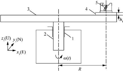
Fig. 1 Schematic diagram of dynamic centrifuge.
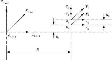
Fig. 2 Coordinate systems of dynamic centrifuge.

Table 1 Homogeneous transformation between adjacent coordinate systems.
The errors of dynamic centrifuge instrument include dynamic and static errors. As shown in Table 1, Δθand Δθrepresent the 2-D perpendicularity of the spindle axis line versus the horizontal plane; Δx(α), Δy(α), and Δz(α) represent the runout error; Δθ(α) and Δθ(α) represent the axial slip error and the wobble error of spindle axis system, respectively;α is the angular position of spindle axis;Δθ,Δθrepresent the 2-D perpendicularity of axis line ozversus the installing surface; Δθ, Δθ, and Δθrepresent the installation attitude error; Δxand Δyrepresent the installation eccentricity of accelerometer; ΔR, ΔRrepresent the static and the dynamic radius measurement error of the centrifuge,respectively; Aand Dare the attitude and displacement of the homogeneous transformation of adjacent coordinate systems, respectively. Based on the error sources analysis and the homogeneous transformation expressions of adjacent coordinate systems, the influence of dynamic centrifuge errors on the reproduction of motion parameter components in quartz pendulum accelerometer coordinate system can be revealed.

where σis the uncertainty of the dynamic centrifuge caused by displacement errors, σrepresents the uncertainty of dynamic centrifuge caused by attitude errors, and ω and R are the angular velocity and the radius of dynamic centrifuge,respectively.
According to the homogeneous transformation of coordinate system oxyzversus oxyz, the input acceleration error caused by displacement errors and attitude errors independently can be derived as shown in Table 2, where Trans()is the displacement function and Rot() the rotation function.
As shown in Table 2,the input acceleration error caused by displacement errors ΔR and attitude errors Δθcan be expressed as

2.3. Uncertainty analysis of dynamic centrifuge
It can be seen from Table 1 that the errors of dynamic centrifuge are composed of displacement errors ΔR and attitude errors Δθ. The displacement errors contain Δx(α), Δy(α),Δx, and Δy. The attitude errors contain Δθ, Δθ, Δθ(α),Δθ(α),Δθ,Δθ,Δθ,Δθand Δθ.During the computation of input acceleration,there must exist computation errors caused by the aforementioned displacement and attitude errors. Therefore, the relative value of the computation acceleration error is the uncertainty of the dynamic centrifuge, as shown in
According to practical experiment requirements, the parameters of dynamic centrifuge are given as Δx(α)=Δy(α)=Δx=Δy=5×10m, Δθ=1, R=0.5 m,and ω=2 rad/s. By substituting Eq. (2) and Eq. (3) into Eq.(1), uncertainty of dynamic centrifuge is σ=9.487×10m/s.
3. Comprehensive specific force input on accelerometer
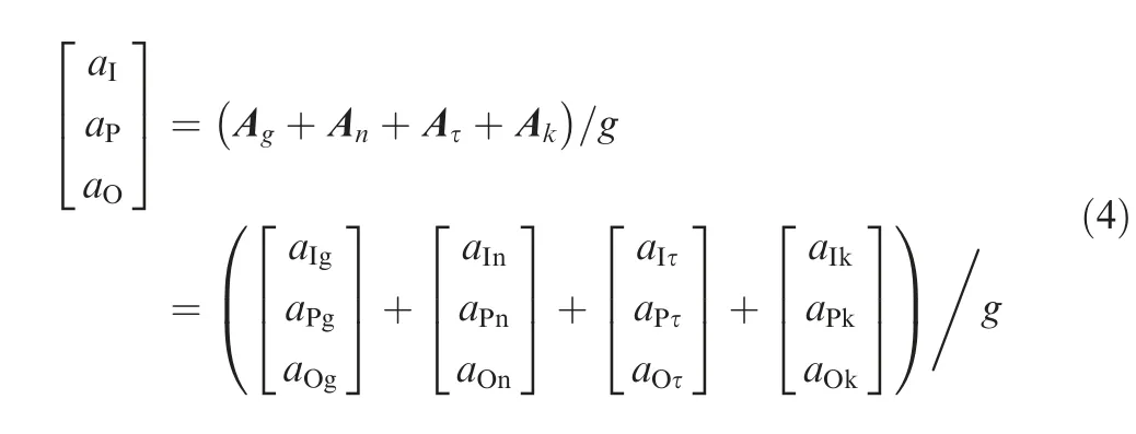
When the dynamic centrifuge spindle rotates with time-varying angular velocity ω(t)=At, there will be four kinds of force inputs of the accelerometer, which are produced by gravityacceleration A,centripetal acceleration A,tangential acceleration A, and Coriolis acceleration A, as shown in

Table 2 Errors of dynamic centrifuge with corresponding input acceleration errors.
(1) Components of specific force produced by gravity acceleration
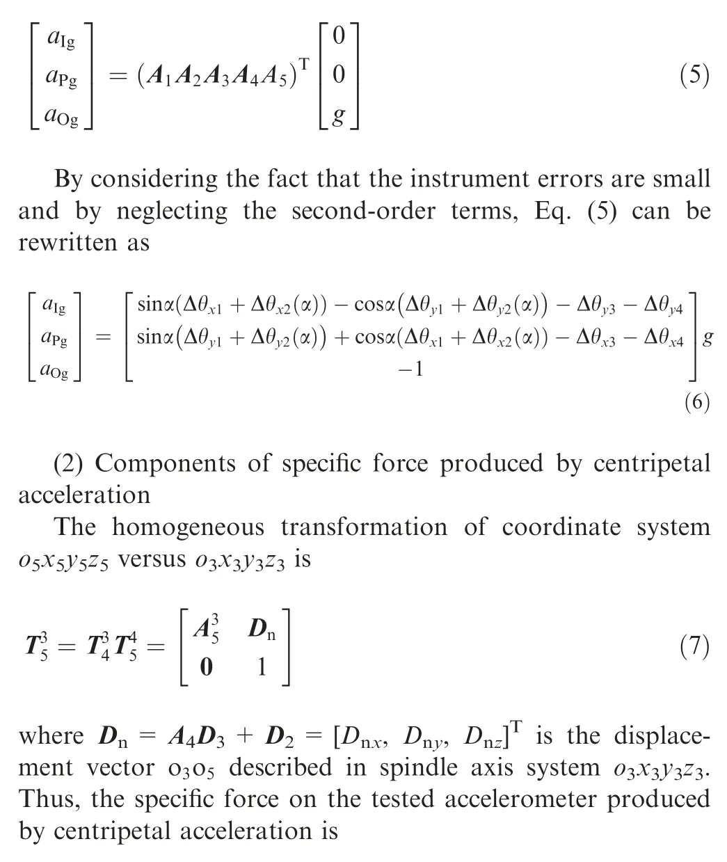
The specific force produced by the acceleration of gravity is expressed as [0, 0, g]in the geographic coordinate system.According to the homogeneous transformation of coordinate system oxyzversus oxyz, the acceleration of gravity can be expressed in the inertial instrument test coordinate system as follows:
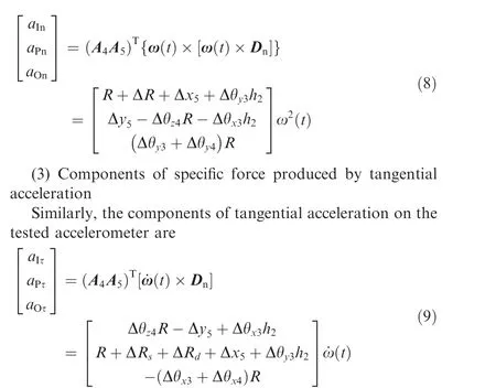
(4) Components of specific force produced by Coriolis acceleration
Coriolis acceleration is generated by the linear velocity of the accelerometer in oxyzwhich rotates at the turn rate of the Earth ω. Thus, the specific force on the tested accelerometer produced by Coriolis acceleration can be written as
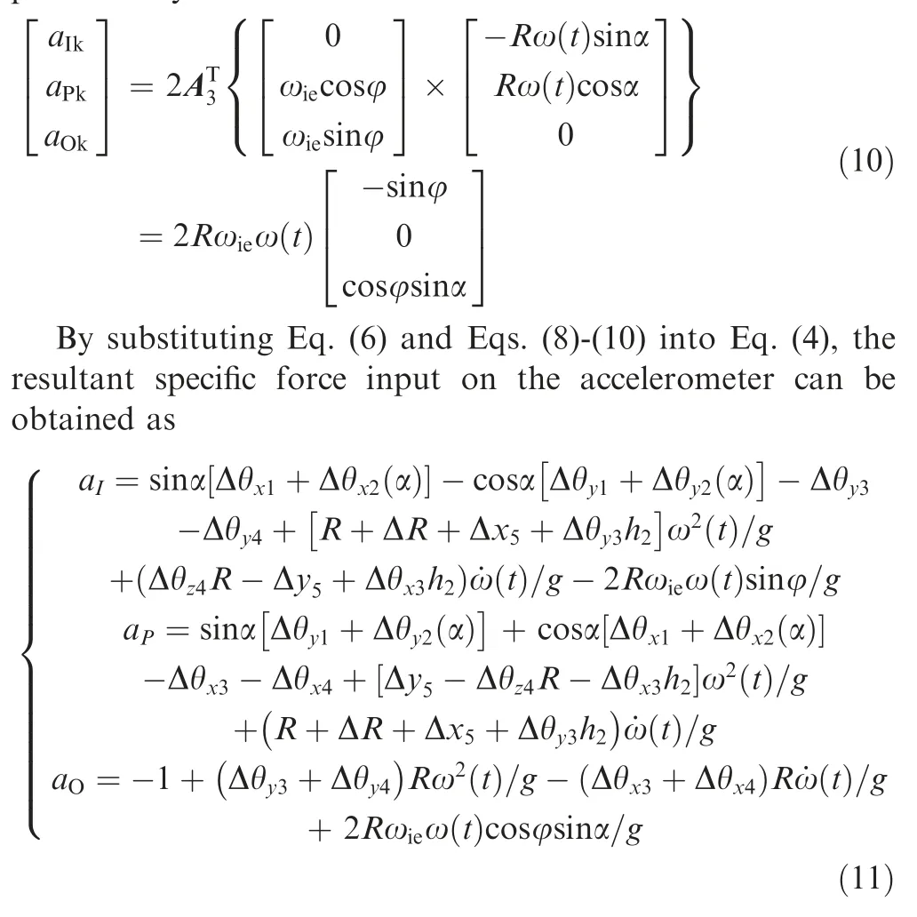
4. Error model and calibration method of accelerometer
4.1. Error model of quartz accelerometer
According to Ref., the error model of the quartz accelerometer is

where Kand Krepresent bias and scale factor, respectively;K, Kare the sensitivities of the coupling axis; K, Kand Krepresent cross-coupling coefficients; K, K, Kand K, K, Kare the second-order and the thirdorder nonlinear coefficients of concerned axes; Krepresents odd-quadratic coefficient; a, a, and aare the acceleration along input, pendulum, and output axes, respectively; U is the output of accelerometer; ε represents random error.
The accelerometer considered in this paper is mainly sensitive to the specific force of the input axis.Thus, the first-order term of Kais reserved.The rest terms of the error model only take nominal values. By substituting a, a, ainto the error model, Eq. (12) can be simplified as
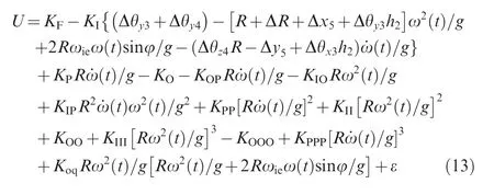
4.2. Calibration method of accelerometer
The test plan of periodic dynamic angular velocity excitation in three attitudes is used to calibrate the error model of accelerometer. The ideal angular velocity during each period is shown in Fig. 3. The attitude of the accelerometer is given in Fig. 4, and we assume that the clockwise rotation direction of centrifuge is the positive direction. Then, from Fig. 3 and Fig. 4, we can see that the curves of ω(t) and ω(t)indicate that the centrifuge gives constant angular accelerations during the time period of 0-tand t-t, and the angular acceleration of ω(t) and ω(t) are the same in the magnitude.
The curve of ω(t) indicates that the centrifuge work with angular rate B(rad/s). To complete data collection, the sampling time and frequency can be designed accordingly.
It is noticed from attitude 1 in Fig. 4 that the accelerometer’s input axis always points to the direction of spindle, the accelerometer’s pendulum axis points to the tangential direction of the centrifuge’s radius, and the output axis is parallel to the spindle. Attitudes 2 and 3 are also shown in Fig. 4.The input of each axis of accelerometer can be simplified as shown in Table 3.
During the dynamic test, the centrifuge generates three angular rate signals ω(t), ω(t), ω(t) for each attitude.And the excitation parameters of the signals are ω(t)=At, ˙ω (t)=A rad/s, ω(t)=B, ˙ω (t)=0 rad/s, ω(t)=B-A(t-t), and ˙ω (t)= -A rad/s. Taking the first installation attitude as an example, the output of accelerometer under three centrifuge excitation conditions is shown in Table 4.
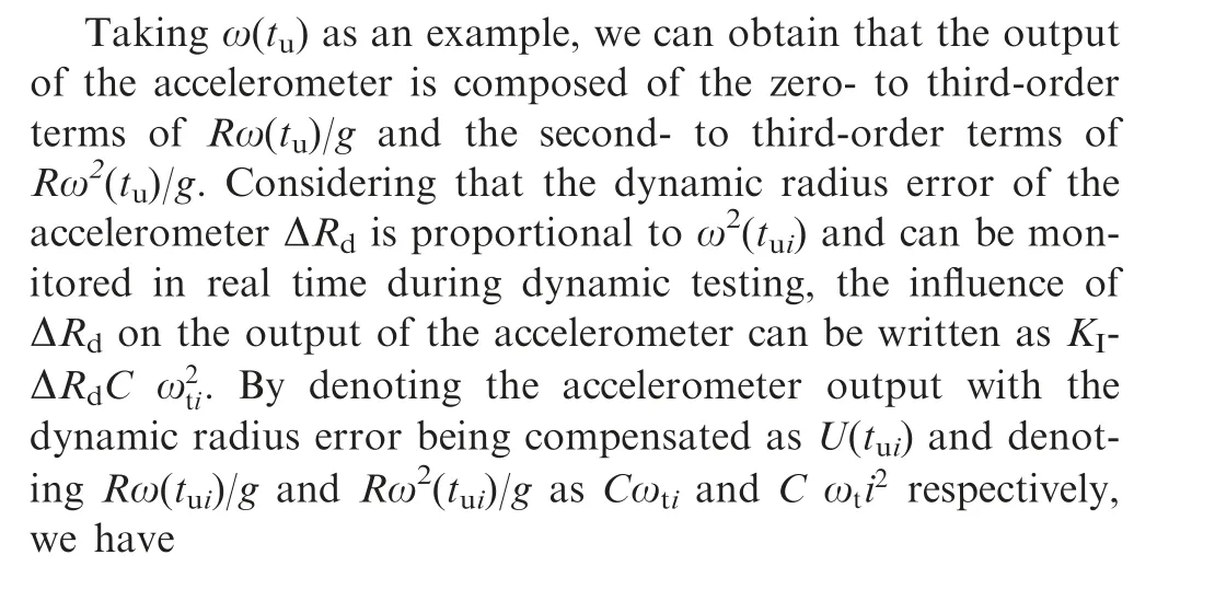

Fig. 3 Schematic diagram of periodic dynamic angular velocity excitation.

Fig. 4 Attitudes of accelerometer.
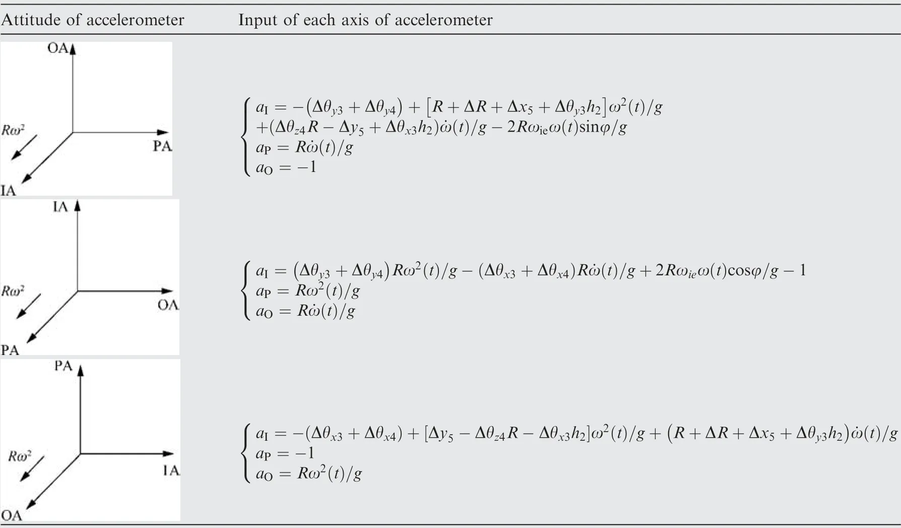
Table 3 Input of each axis of accelerometer under different attitudes.
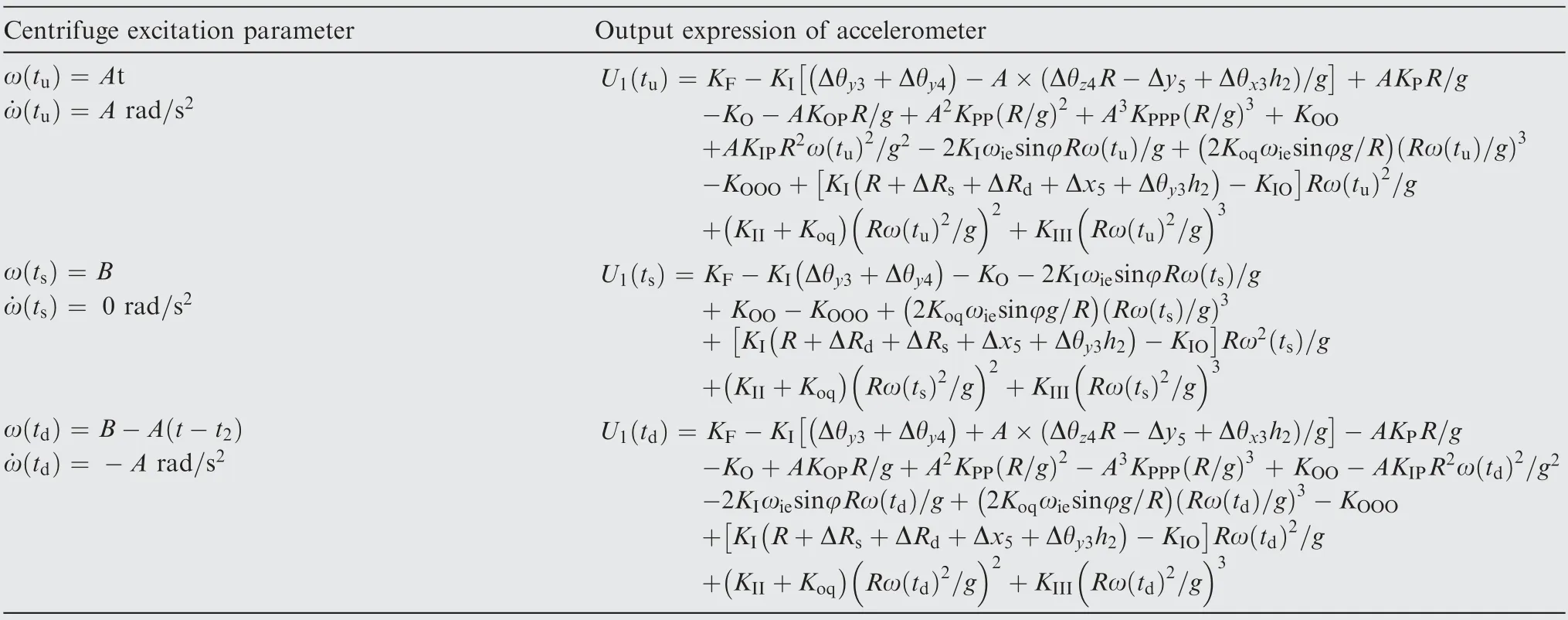
Table 4 Output expression of accelerometer under three centrifuge excitation conditions.

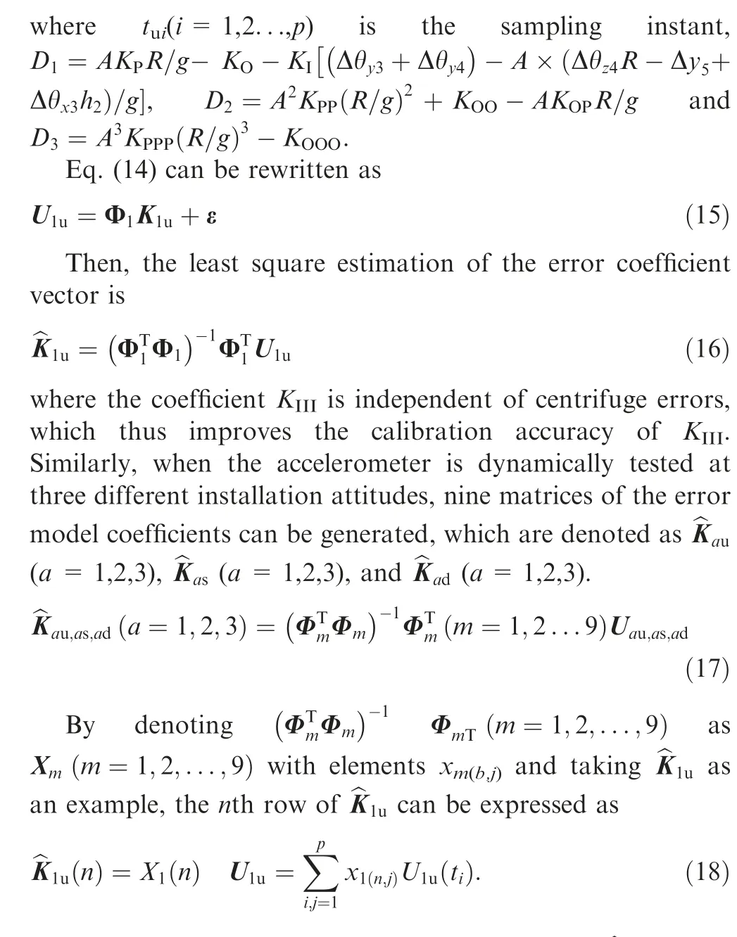
Similarly,other rows of the coefficient matrices, ^K(n),(a=1,2,3) can be obtained. The odd-quadratic coefficient,second-order and third-order nonlinear coefficients in the error model of the accelerometer can be identified by synthesizing all error coefficient vectors.The expressions of the corresponding error model coefficients are shown in Table 5. For the quartz pendulum accelerometer, K, Kcan be accurately calibrated by a horizontal indexing table,which are thus taken as known parameters during the subsequent identification process.According to Table 5,K,K,K,K,Kcan be identified during each sampling period of dynamic tests. Finding the mean value of identification results of each stage can reduce the uncertainty of the unidentified error model coefficients and improve the identification accuracy. The estimates of all the error model coefficients except Kare independent of the instrument errors, which implies that the estimation accuracy of the coefficients is improved. Since the excitation of dynamic test is periodic, multi-period sampling can be performed in a dynamic test to reduce the uncertainty of the identified error model coefficient.
5. Simulation verification and error analysis
To meet the requirement of the dynamic test, A can be set as 20. Therefore, ω(t), ω(t), ω(t) and their derivative can be written as ω(t)=20t rad/s,˙ω(t)=20 rad/s, ω(t)=20 rad/s, ˙ω (t)=0 rad/s, ω(t)=20-20 (t-t) rad/s,˙ω(t)= -20 rad/s,respectively.Assuming that the local latitude is φ=45°, the angular velocity of the Earth rotation is ω=7.292×10rad/s, the local gravitational acceleration is g=9.78 m/s, and the radius of the dynamic centrifuge is R=0.5 m. Then, by denoting the uncertainty of local gravitational acceleration,the radius of dynamic centrifuge,and the output of quartz pendulum accelerometer as σ=10g,σ=10m and σ=10V respectively, the uncertainty of Kcan be expressed as

Fig. 5 shows the values of the uncertainties of the secondand third-order error coefficients under different sampling points.
Fig.5 shows that the uncertainties of the second-and thirdorder error coefficients decrease, as the number of sample points increases.When the number of sampling points exceeds 100, the calibration accuracy of σand σwill be guaranteed less than 10g and 10g respectively, and the uncertainty will become smaller gradually.Therefore, in orderto ensure the accuracy and efficiency during the calibration process, the number of sampling points p is set to be 100 for testing. Similarly, the uncertainties of other coefficients are shown as
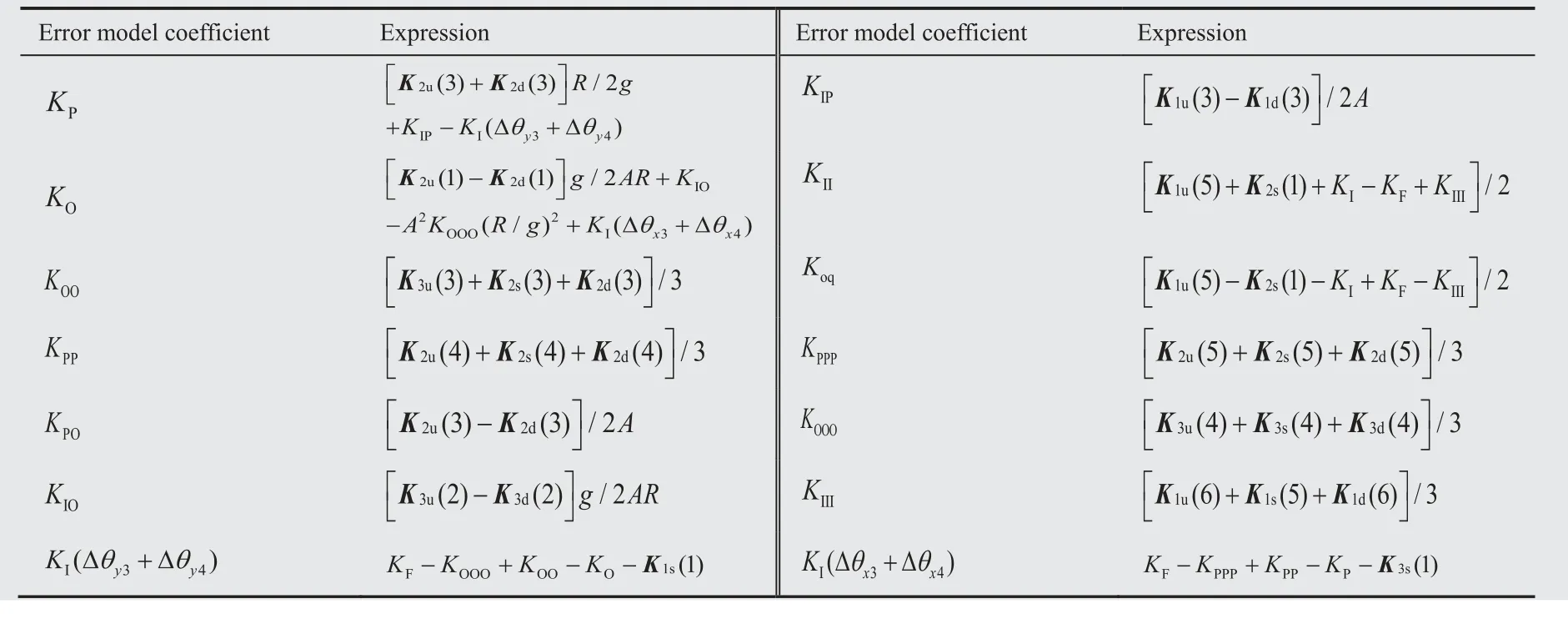
Table 5 Expressions of corresponding error model coefficients.
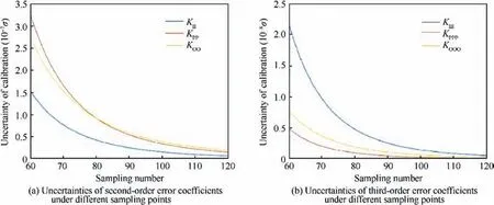
Fig. 5 Uncertainties of second-order and third-order error coefficients under different sampling points.
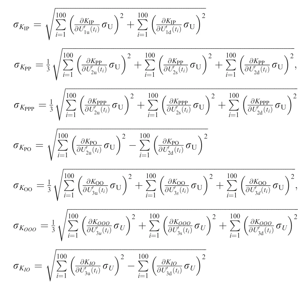

Ignoring the calculation process, the uncertainties of the error model coefficients are shown in Table 6.
The error coefficients of the accelerometer are shown in Table 7. Substituting the error coefficients of the accelerometer, the acceleration of each axis and system noise into the error model, we obtain the centripetal acceleration, tangential acceleration and the output of the accelerometer, which are shown in Fig. 6.
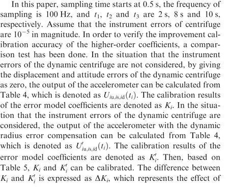
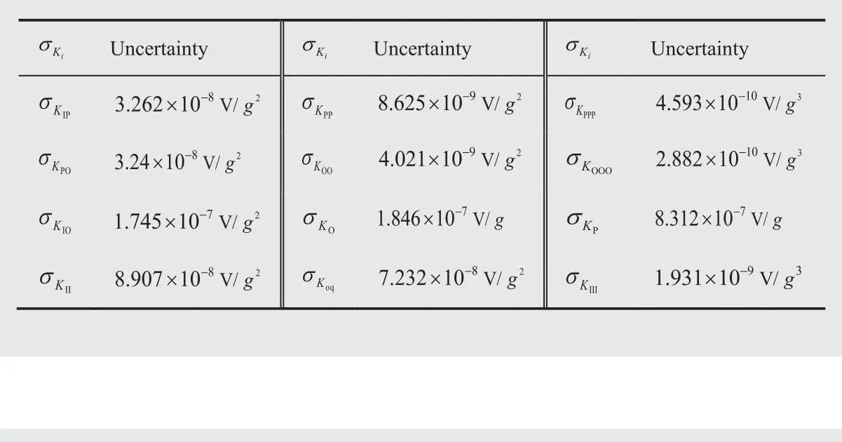
Table 6 Uncertainties of error model coefficients.
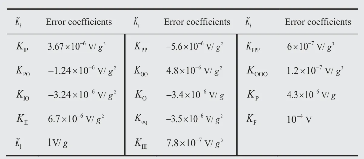
Table 7 Error coefficients of accelerometer.
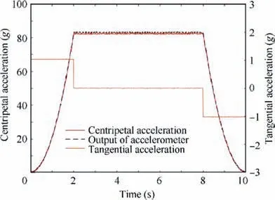
Fig. 6 Centripetal acceleration, tangential acceleration and output of accelerometer.
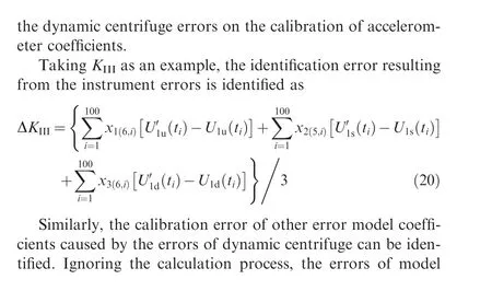

Table 8 Errors of model coefficients.
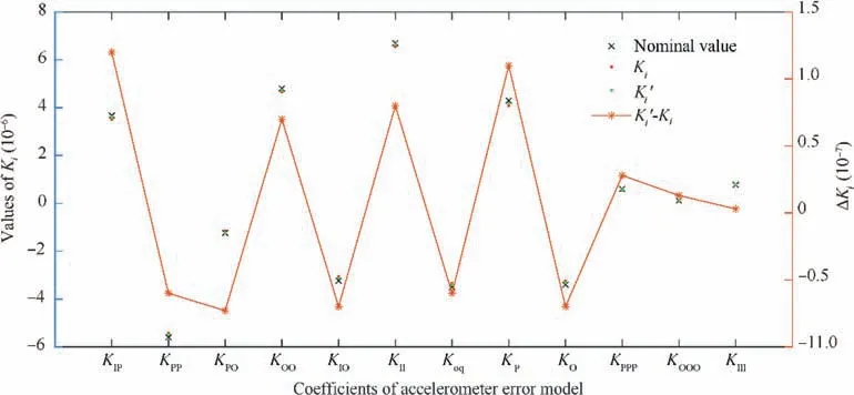
Fig. 7 Identification results of error coefficients.
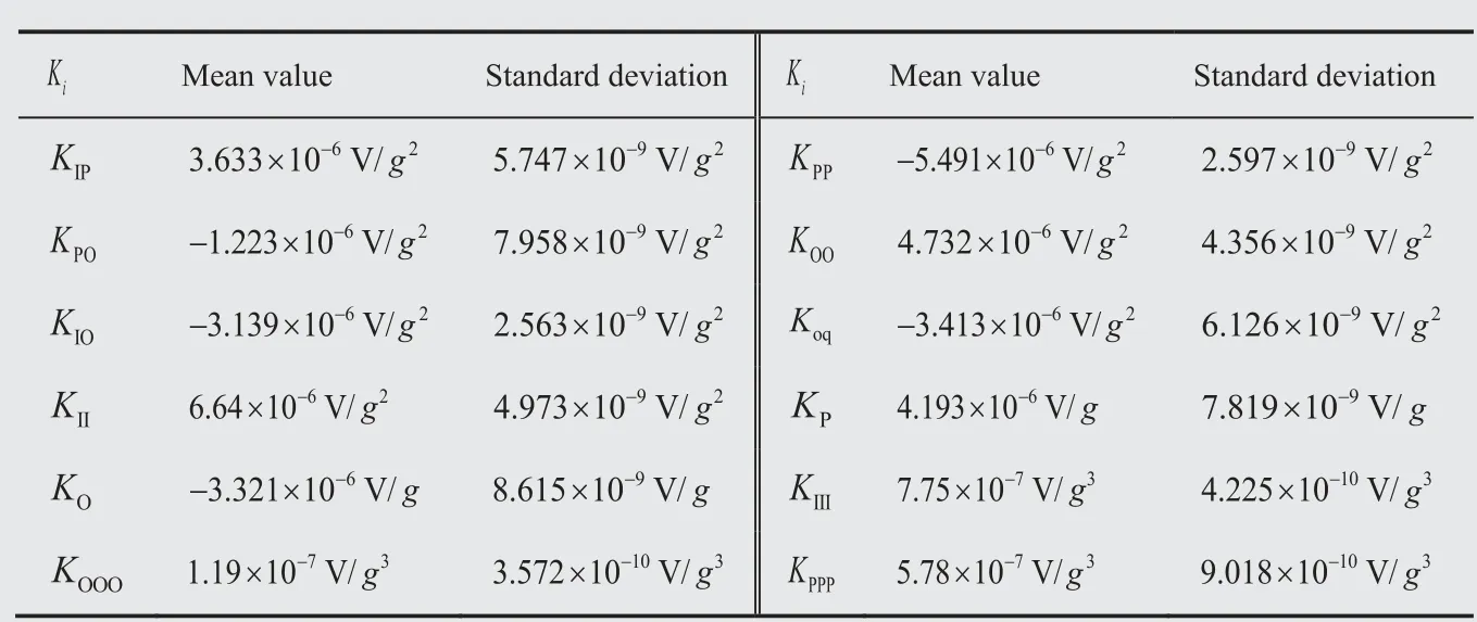
Table 9 Mean value and standard deviation of error model coefficients.

It is shown that the instrument errors of dynamic centrifuge have great influence on the cross-coupling terms, the thirdorder terms and the singular terms related to the input axis.And if the instrument errors are considered, the calibration value will be closer to the nominal one.
The calibration tests have been done for several times, and the mean value and standard deviation of each coefficient of error model are given in Table 9.Taking Kand Kas examples, the calibration values of these two variables are given in Fig. 8, which shows that the mean values of Kand Ktend to be fixed constants as the number of tests increases. This directly shows the repeatability of the proposed calibration method. Besides, it is noticed from Table 9 that the standard deviation of each coefficient of error model is one percent less than that of its mean value. This further demonstrates the repeatability of the proposed method.
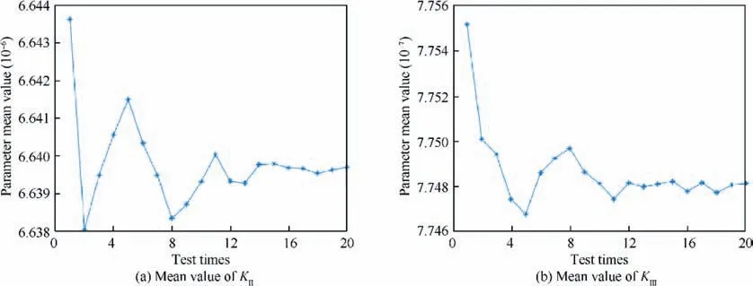
Fig. 8 Mean value of KII and KIII as the number of tests increases.
To sum up,compared with traditional test method,the calibration method proposed in this paper can generate a continuous dynamic acceleration excitation, which well reflects the variation of acceleration in practical engineering.Besides,during the calibration process, the number of installing positions with the proposed method is much fewer than that with traditional method, which improves the calibration efficiency.What’s more,by compensating for the effect of the instrument errors of dynamic centrifuge, the calibration accuracy is improved at the same time.
6. Conclusions
(1) The instrument errors and the uncertainty of dynamic centrifuge and the comprehensive specific forces input on the accelerometer are analyzed.Then,the calibration model of the accelerometer is established.
(2) In order to calibrate the coefficients of acceleration error model efficiently,a test plan with three kinds of dynamic excitation signals under one mounting mode is proposed.The influence of the dynamic centrifuge instrument errors and the installation errors of the accelerometer on the accuracy of coefficients identification is eliminated. As the number of attitudes decreases, alignment errors caused by manufacturing structure are reduced,and time costs of the test are reduced at the same time.
(3) The simulation verifies that the higher-order identification coefficients can be calibrated effectively, and the accuracy of each coefficient increases after compensating for the centrifuge errors. The repeatability of the proposed calibration method is verified by several calibration tests.
(4) This method can be applied to the fast calibration process of quartz accelerometers, and is the base of the design of dynamic centrifuges and the base of the design of test plan for accelerometers.
The authors declare that they have no known competing financial interests or personal relationships that could have appeared to influence the work reported in this paper.
 Chinese Journal of Aeronautics2022年6期
- Chinese Journal of Aeronautics的其它文章
- Experimental investigation of a gliding discharge plasma jet igniter
- Evolution of turbulent boundary layer over a three-dimensional bump
- Conceptual design and preliminary experiment of icing risk management and protection system
- Direct thrust control for multivariable turbofan engine based on affine linear parameter-varying approach
- Characteristics of reattached boundary layer in shock wave and turbulent boundary layer interaction
- Structurally coupled characteristics of rotor blade using new rigid-flexible dynamic model based on geometrically exact formulation
