Numerical investigation on leakage and rotordynamic performance of the honeycomb seal with swirl-reverse rings
Chengjing GU, Wanfu ZHANG, Xingchen YANG, Kexin WU, Lu YIN
School of Energy and Power Engineering, University of Shanghai for Science and Technology, Shanghai 200093, China
KEYWORDS Computational Fluid Dynamics (CFD);Honeycomb seal;Leakage;Rotordynamic performance;Stability;Swirl-Reverse Ring (SRR)
Abstract Honeycomb seals are a crucial component to restrict the leakage flow and improve system stability for the turbomachines and aero-engines. In this work, the leakage and rotordynamic performance of honeycomb seals with the Swirl-Reverse Ring(SRR)is predicted by employing the approach of Computational Fluid Dynamics(CFD)and the multifrequency whirling model theory.Numerical results show that the positive preswirl flow and circumferential velocity can be effectively weakened for the honeycomb seal as SRR is introduced.The obtained results also suggest that the direct stiffness, direct damping, and effective stiffness will not reduce, for the honeycomb seal is introduced to SRR. However, the honeycomb seal with SRR can significantly reduce the crosscoupled stiffness and remarkably enhance the effective damping. Meanwhile, the absolute value of negative tangential force acting on the rotor surface significantly increased for the honeycomb seal introduced SRR. Therefore, the whirling velocity of the rotor would be weakened. This phenomenon would be conducive to improve the stability of the rotor. Besides, the performance of SRR can be further enhanced when SRR possesses a smaller bending angle, and a higher arrangement density and height.
1. Introduction
The annular labyrinth seal is one of the critical components to reduce the leakage flow for the steam/gas turbines,pumps,and compressors.However, previous experiments and numerical studies have demonstrated that the annular labyrinth seal could easily produce a destabilized fluid-excitation force acting on the rotor surface in the seal cavity.This would lead to a sharp drop in rotor stability. Therefore, in recent years, many damper seals,such as the honeycomb seal,hole-pattern seals,pocket damper seals,and the scallop seal,were proposed and widely used to replace the conventional labyrinth seal.
Compared with other damper seals, many studies indicate that the honeycomb seal not only possesses an excellent performance to restrain the leakage flow rate but also shows a good damping characteristic.In 1989,Childs et al.firstly measured the rotordynamic characteristics of honeycomb seals. Their measurement results show the honeycomb seal provides an outstanding rotordynamic performance. In 1999, Soto and Childstested the leakage and rotordynamic performance of the labyrinth seal operating under shunt injection conditions and compared the test data with the honeycomb seal. They found the honeycomb seal possesses the minimum leakage flow rate and the highest effective damping coefficient when the pressure ratio is greater than 0.45. In 2002, Dawson and Childsexperimentally investigated the leakage performance and rotordynamic characteristics of the smooth annular seal and the honeycomb seal. Their results implied that the honeycomb seal shows a higher effective stiffness coefficient at all tested frequency domains(40-230 Hz)and a superior effective damping coefficient at a lower frequency(<120 Hz).In recent years, many investigations continue to study the effects of the operating conditions and geometry parameters on the rotordynamic performance of the honeycomb seal. Weatherwax and Childsexperimentally studied the influence of the rotor eccentricity(0-0.5)on rotordynamic characteristics of the honeycomb seal. They discovered that the rotordynamic coefficients are not sensitive to the eccentric condition. Sprowl and Childsreported the effect of inlet positive preswirl flow on the rotordynamic performance for the honeycomb seal. Their results indicated that the positive preswirl flow would lead to the cross-coupled stiffness increases briskly, then causes a reduction in the magnitude of effective damping and an increase in the crossover frequency.Smalley et al.experimentally researched the rotordynamic characteristics of a Divergent-Tapered Honeycomb Seal(DTHCS).Their achievements showed that the DTHCS could further increase the peak value of the effective damping coefficient for the honeycomb seal. Van der Velde and Childsinvestigated the dynamic characteristics of the Convergent-Tapered Honeycomb Seal(CTHCS) and Constant Clearance Honeycomb Seal(CCHCS). They found that the CTHCS possesses a better rotordynamic performance than the CCHCS.
In fact, except for the damper seals. The swirl brake technology is also employed to enhance the stability of the labyrinth seal. The swirl brakes are a range of vanes arranged at the seal entrance to suppress the entrance preswirl flow and reduce the cross-coupled force in the seal cavity. In 1980,Benckert and Wachterfirstly tested the rotordynamic coefficients for the labyrinth seal with a series of swirl brakes at the seal entrance. Their experiment result displays that the swirl brakes could significantly reduce the cross-coupled forces and improve seal stability. Sivoand Nielsenet al. demonstrated the effectiveness of swirl brakes in reducing the positive tangential force and inverting the fluid preswirl at the seal entrance for the labyrinth seal.Recently,some researchers also investigated the effect of the geometric parameters of the swirl brakes on the leakage flow rate and rotordynamic characteristics for the labyrinth seal.Nielsen et al.investigated the influence of two interchangeable swirl brakes for the High-Pressure Fuel Turbopump(HPFTP).Their measuring result proves the validity of a no-aerodynamic swirl brake design, and the results also show that the no-aerodynamic swirl brake design is better than the aerodynamic design. Childs et al.tested the rotordynamic performance of the labyrinth seal with the negative-swirl brakes at the seal entrance.Their results suggest that the negative-swirl brakes could significantly reduce the cross-coupled stiffness coefficient and produce a remarkable increase in the effective damping coefficient. Moreover,Sunand Untaroiuet al.reported the influence of geometric parameters of the swirl brakes including arrangement density,length,width,tilt angle on the leakage,and rotordynamic characteristics of the labyrinth seal.These works provide valuable data for the optimal design of the swirl brakes.
Besides, some studies have shown that the effectiveness of the swirl brakes is sometimes restricted for long labyrinth seals.To further improve the reliability of the conventional swirl brake, Li et al.proposed the Swirl-Reverse Ring(SRR)and integrated it with typical labyrinth seals,then investigated its effectiveness. Their result indicates that SRR could significantly decrease the preswirl velocity of flow at the seal entrance to zero or even negative. For the honeycomb seal,the previous investigation of Sprowl and Childsshowed that the positive preswirl flow is not beneficial to the stability of the rotor. Their investigations proved the necessity of employing the swirl-reverse device to enhance effective damping and decrease the crossover frequency. However, rare publications can be found to predict the leakage and rotordynamic performance of the honeycomb seal with the swirl-reverse device.Moreover, the effects of geometric parameters of the swirlreverse device on the leakage and rotordynamic characteristics of the honeycomb seal are still unclear.
This paper aims to employ the numerical method and multifrequency elliptical whirling orbit modelto investigate the leakage and rotordynamic characteristics of the honeycomb seal integrating with SRR.The objective of this work is to figure out the influences of the various swirl-reverse rings on the honeycomb seal leakage and rotordynamic performance and provide useful guides and suggestions for its structural design.
2. Numerical method
2.1. Physical model
In this work, the geometric parameters of the honeycomb seal are derived from the author’s laboratory.Fig.1 shows the honeycomb seal with SRR. In the basic design, the arrangement density along the circumferential N is 30. The length l of SRR was 3.0 mm,the radius r was 0.6 mm at the head and tail of SRR.Meanwhile,the height h of SRR was 3.3 mm,and the bending angle θ was 45°.Moreover,the depth H,width w,wall thickness d, and seal clearance Cof the honeycomb seal are 3.3 mm, 2.5 mm, 0.2 mm, and 0.2 mm, respectively. The seal length L and rotor radius R are 38 mm and 30 mm. Table 1 lists the detailed geometric parameters of the honeycomb seal and SRR.
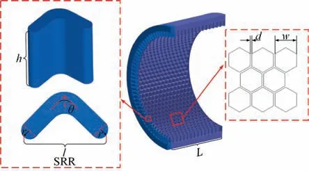
Fig. 1 Geometric model of honeycomb seal with SRR and design parameters.
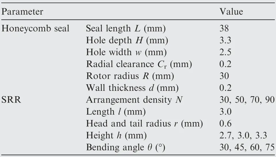
Table 1 Detailed geometric parameters of honeycomb seal and SRR.
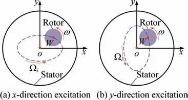
Fig.2 Elliptical orbits whirling model for rotor vibration with a single frequency.
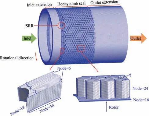
Fig. 3 Detailed grid distribution of numerical model with 6.32 million nodes.
2.2. Numerical approach
In this paper, a fully three-dimensional numerical model was established to investigate the leakage and rotordynamic performance of the honeycomb seal with SRR.The leakage flow rate and rotordynamic coefficients were predicted by the computa-tional fluid dynamics and multifrequency elliptical whirling orbit model theory.Fig. 2 displays the whirling orbit for the rotor whirling at a single frequency excitation in x and y direction.The rotor spins the rotor center W with a rotational speed ω;meanwhile,the rotor also whirls the seal center o with a whirling angular velocity Ω.
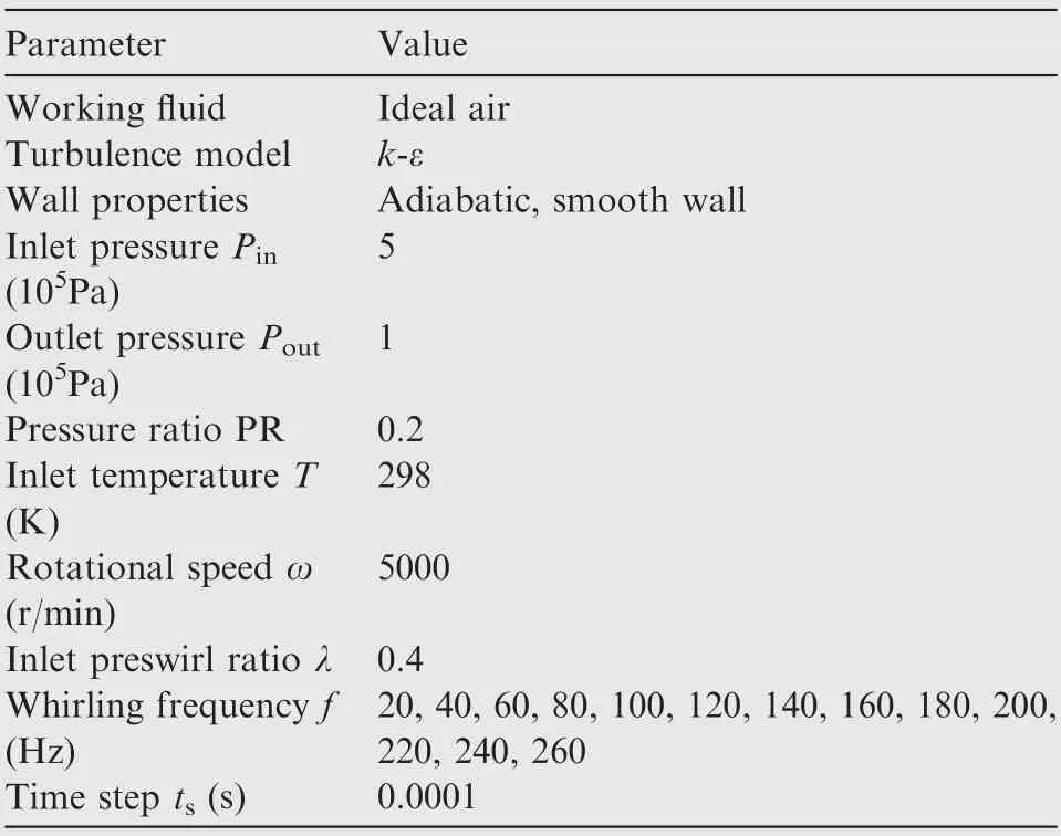
Table 2 Working parameters and boundary conditions.
In Fig. 2(a) the whirling displacement at the x-direction excitation of the rotor can be expressed as
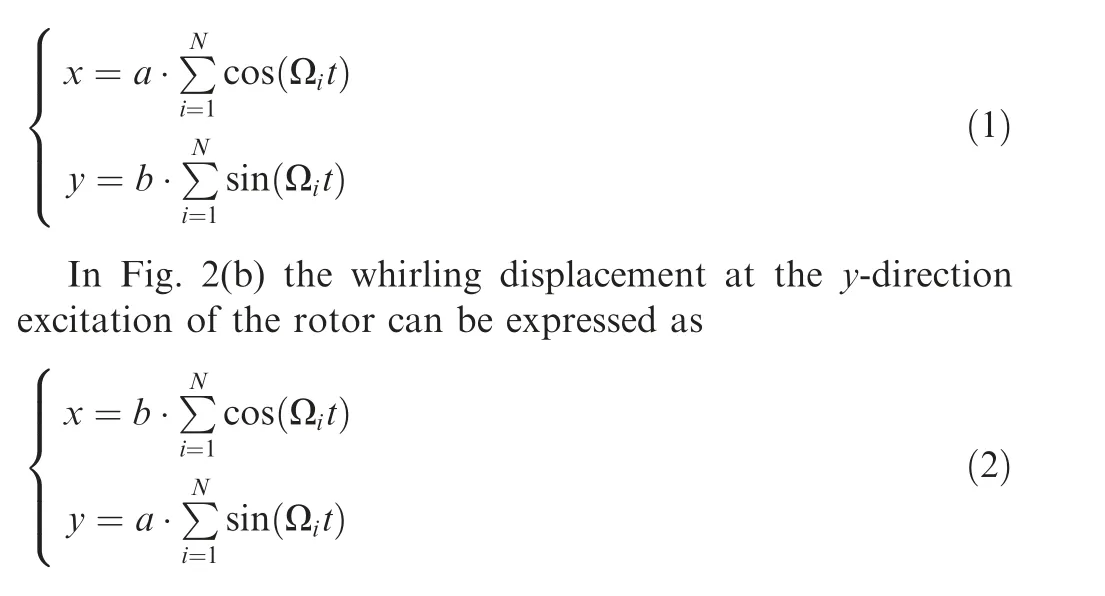
where a = 0.1C/S (S represents the total number of whirling frequencies, S = 13) and b = 0.5a are the semi-major and semi-minor axis of the ellipse whirling orbit, respectively. A complete period of multifrequency excitation Tand the time step tare 0.1 s, 0.0001 s. The angular speed is expressed as Ω=iΩ=2πif,and the frepresents the fundamental frequency (f= 20 Hz, i = 1, 2, ..., 13).
For the rotor whirling around the seal center with a small motion, the relationship between the flow-induced forces (F,F), stiffness coefficients (K, K, K, K), damping coefficients (C, C, C, C) can be described as

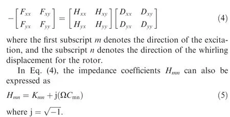
In Eq. (5), Kis related to the stiffness coefficients of the seal. The imaginary part j(ΩC) would determine the damping coefficients. The flow-induced forces Fand whirls displacement Dcould be obtained from the computational fluid dynamics method.
Finally, the stiffness and damping coefficients in x and y direction excitation can be represented as
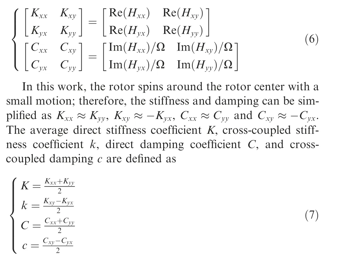
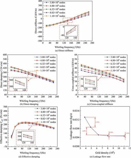
Fig. 4 Influence of grid densities on rotordynamic coefficients and leakage flow rate for honeycomb seal (N = 30, l = 3.0 mm,r = 0.6 mm, h = 3.3 mm, θ = 45°).
Besides, the effective stiffness coefficient Kand the effective damping coefficient Care usually defined to describe the stability of the rotor-bearing-seal system.The Ccould not only judge the stability of the rotor-bearing-seal system but also can be beneficial to measure the magnitude of stability for the rotor-bearing-seal system. Kand Care defined as follows:

where Fand Fare the forces in radial and tangential direction, respectively; δ is the eccentricity of the rotor.
2.3. Grid distribution and boundary conditions
Fig.3 displays the structured grid distribution of the numerical model with 6.32 million nodes (N = 30, l = 3.0 mm,r = 0.6 mm, h = 3.3 mm, θ = 45°). The full threedimensional numerical model includes four parts, the inlet extension, the swirl-reverse ring, the honeycomb seal, and the outlet extension. For the detailed grid configuration, the grid nodes in the inlet and outlet extension sections are 0.18 and 1.03 million, respectively. What is more, the total grid nodes for the honeycomb seal are 4.42 million, and the grid nodes of the swirl-reverse ring part are 0.72 million. Meanwhile,the honeycomb seal clearance and the hole are connected by an interface boundary, where the grid nodes of the interface for the two parts are 0.12 and 0.17 million, respectively.Besides, the rotor is set as the moving boundary to simulate the whirling rotor by using the grid deformation technology,and the grid nodes on the rotor surface are 0.12 million.
Table 2 gives the working parameters and boundary conditions of the honeycomb seal. The total pressure and temperature conditions were set at the seal entrance, while the outlet was set as the average static pressure condition. The standard k-ε turbulence model was employed, the working fluid is the ideal air, and all the wall was set as the adiabatic and smooth wall. Besides, the inlet positive preswirl condition was also considered. The inlet preswirl ratio λ is defined as λ = 60V/(2πRω), where the Vis the average circumferential velocity at the seal entrance.
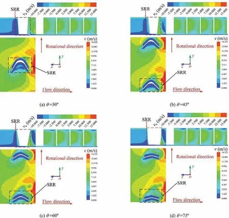
Fig.5 Velocity distribution for honeycomb seal with various bending angles of SRR(N=30,l=3.0 mm,r=0.6 mm,h=3.3 mm).
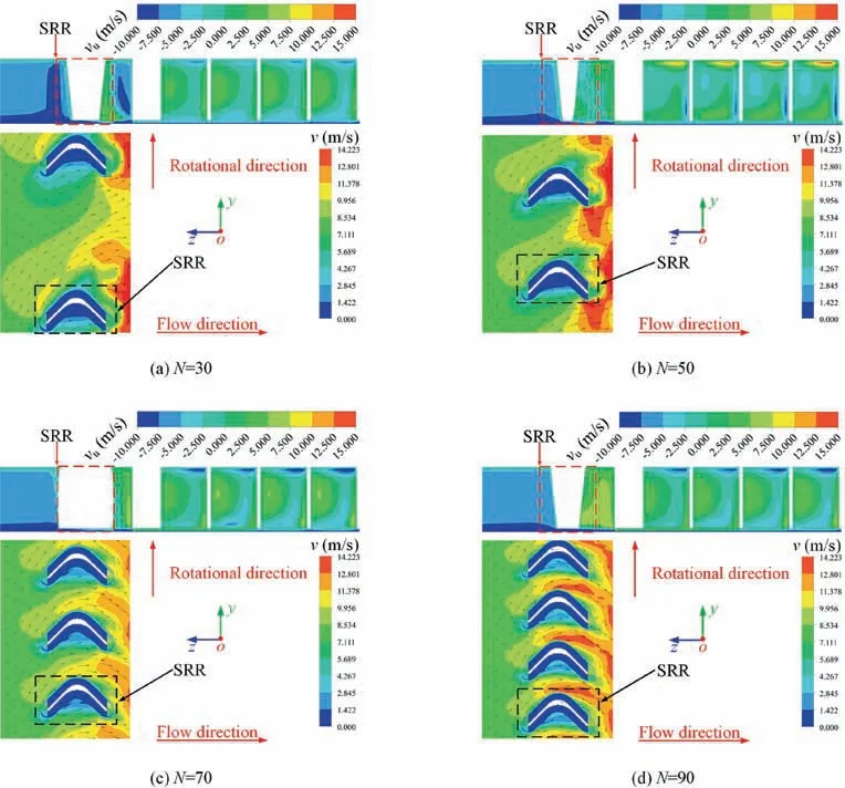
Fig. 6 Velocity distribution for honeycomb seal with various arrangement densities of SRR (θ = 45°, l = 3.0 mm, r = 0.6 mm,h = 3.3 mm).
What is more, the convergence targets for all governing equations should be achieved for the steady-state and transient conditions. The steady-state condition is regarded as meeting the required accuracy when the residual error of the momentum, mass, and energy equations are lower than 10. In the transient calculational condition, the monitoring curve of the flow-induced forces should be smooth and the difference of force magnitude for different periods is less than 0.1%.Meanwhile, the residual of all equations should be lower than 10.
2.4. Effectiveness of numerical method
The CFD method has been widely applied to predict the leakage flow rate and rotordynamic performance for the annular seals. In this paper, a full 3D transient CFD method was employed to solve the unsteady equations by a commercial software ANSYS-CFX.Many previous works have verified the effectiveness of this transient CFD method to predict the rotordynamic coefficients of various annular seals.
What is more, the grid division has a significant influence on predicting the rotordynamic coefficients and leakage flow rate for the honeycomb seal. Taking the honeycomb seal with SRR(N=30,l=3.0 mm,r=0.6 mm,h=3.3 mm,θ=45°)as an example, five different grid densities (3.80 million, 4.88 million, 6.32 million, 8.02 million, and 11.00 million) were employed to predict its rotordynamic coefficients and leakage flow rate, and then obtained a proper grid division.
Fig. 4 gives the effect of five grid densities on the rotordynamic coefficients and leakage flow rate for the honeycomb seal. As plotted in Fig. 4(a), the numerical results show that the K is insensitive to the increase of grid density for f<120 Hz. However, a lower grid density has a considerable effect on the K for f > 120 Hz. Compared to the results with 3.80 million nodes and 4.88 million nodes,the predicted results are more accurate when the nodes increase from 6.32 million to 11.00 million. As explained in Fig. 4(b), we can see that the predicted results of C are poorer when the grid density is below 6.32 million nodes.On the contrary,the simulated results of C almost keep a constant value when the grid density increases from 6.32 million nodes to 11.00 million nodes. As shown in Figs. 4(c) and 4(d), we can find that the predicted results of k and Care more accurate when the grid density is greater than 4.88 million.
On the other hand, as portrayed in Fig. 4(e), the leakage flow rate decreased by 2.15%when the grid density rises from 3.80 million to 4.88 million. However, the leakage flow rate reduces less than 0.30%as the grid density nodes increase from 6.32 million to 11.0 million. This result suggests that the leakage flow rate is not sensitive to the grid density when the nodes reach 6.32 million. Overall, considering the numerical precision and computational resource, the model with 6.32 million nodes could be employed to simulate the three-dimensional flow for the honeycomb seal.

Fig. 7 Velocity distribution for honeycomb seal with various heights of SRR (N = 30, θ = 45°, l = 3.0 mm, r = 0.6 mm).
3. Results and discussion
3.1. Effects of SRR on velocity distribution
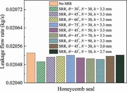
Fig. 8 Leakage flow rate of honeycomb seal with and without SRR.
Fig. 5 describes the velocity distribution v at the seal entrance and the circumferential velocity valong the axial direction for the honeycomb seal with various bending angles of SRR(N = 30, l = 3.0 mm, r = 0.6 mm, h = 3.3 mm). As shown in Fig. 5, the numerical result shows that the seal with SRR could significantly weaken the flow preswirl at the seal entrance.Moreover,it also can be seen that the bending angle plays a key role in restricting the flow preswirl at the seal entrance. For the bending angle θ = 30°, 45°, a majority of the flow direction is altered against the rotation direction.Overall, the numerical results show that SRR with a smaller bending angle is beneficial to restrict the flow preswirl at the seal entrance.
Fig. 6 depicts the velocity distribution at the seal entrance and the circumferential velocity along the axial direction for the honeycomb seal with various arrangement densities of SRR (θ = 45°, l = 3.0 mm, r = 0.6 mm, h = 3.3 mm). As described in Fig.6,the numerical results indicate that a higher arrangement density is conducive to enhance the performance of SRR.We can see that only a small part of the flow direction is altered against the rotation direction for N = 30, 50, while most of the flow still keeps the original flow direction. However, as shown in Figs. 6(c) and 6(d), the numerical results show that almost all the flow direction is altered against the rotation direction at the tail of SRR for N = 70, 90.
Fig. 7 displays the velocity distribution at the seal entrance and the circumferential velocity along the axial direction for the honeycomb seal with various heights of SRR (N = 30,θ = 45°, l = 3.0 mm, r = 0.6 mm). Because a higher circumferential velocity at the seal entrance tends to weaken the system stability, the results show that SRR with a higher h is conducive to improve the performance of SRR. As plotted in Fig. 7, a large low-circumferential velocity area can be observed. A majority of the flow direction is altered against the rotation direction at the head and tail of SRR when the height h is 3.3 mm.
3.2. Leakage performance of honeycomb seal
Fig. 8 gives the leakage flow rate for the honeycomb seal with or without SRR.The leakage flow rate of the honeycomb seal with SRR is lower than that without SRR. Moreover, the numerical results also show that the leakage flow of the honeycomb seal increases with the increase of bending angles,arrangement density, and height of SRR.
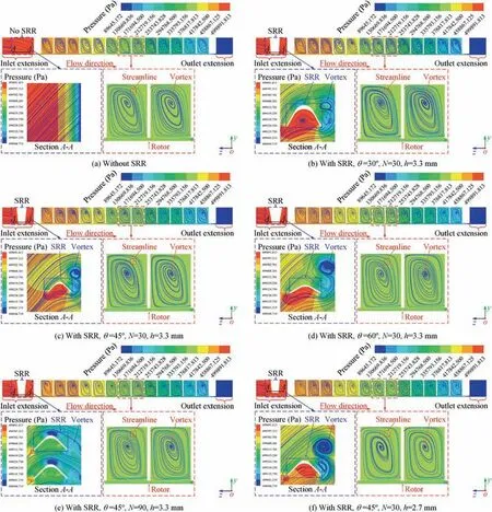
Fig. 9 Static pressure and velocity streamline distribution in meridian plane for honeycomb seal.
Fig.9 shows the static pressure and velocity streamline distribution in the meridian plane for the honeycomb seal.Results show that the static pressure gradually decreases from entrance to exit for all studied conditions, and the velocity streamline presents a spiral distribution in the seal cavity.This phenomenon is mainly produced by the eddy dissipation effects that occur in the honeycomb hole. What is more, it can be seen clearly that the honeycomb seal with SRR would significantly improve the flow patterns at the seal entrance.The honeycomb seal with SRR would lead to the flow direction against the rotation direction. This is conducive to forming the ‘‘vortex” at the head and tail of SRR, and would further strengthen the eddy dissipation effect in the seal cavity.
Besides,as displayed in Figs.9(b),9(c),and 9(d),the results also show that the bending angle plays a key role to promote the fluid forming the ‘‘vortex” at the head and tail of SRR.It can be seen that the case of θ = 30° is more beneficial to the formation of the ‘‘vortex”. As plotted in Figs. 9(c), 9(e),and 9(f), we can also observe that the velocity streamline distribution is more intensive in the seal cavity with increasing N and h of SRR.
Generally, the numerical results suggest that SRR possessing a smaller bending angle,a higher arrangement density,and height is beneficial to the reduction of the leakage flow rate for the honeycomb seal.
3.3. Rotordyanmic performance of honeycomb seal with SRR
Fig.10 displays direct stiffness K versus whirling frequencies f.The K gradually transfers from negative to positive with the increasing f for all studied conditions. Moreover, compared with the seal without SRR, the direct stiffness K of the seal with SRR would increase slightly with the growing bending angle, arrangement density, and height.

Fig. 10 Direct stiffness K vs whirling frequencies f.
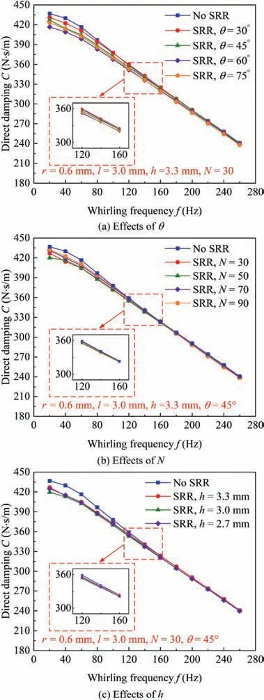
Fig. 11 Direct damping C vs whirling frequencies f.
Fig.11 describes direct damping C versus whirling frequencies f. The C shows a positive value for all studied conditions,and the C decreases with the increasing f.What is more,the C of the seal with SRR would slightly decrease for f < 120 Hz with the increase of θ, N, and h. However, the varying θ, N,and h have little effect on the C for f > 120 Hz. Generally,the C is not sensitive to the changes in geometric parameters of SRR.
Fig. 12 illustrates the cross-coupled stiffness k versus whirling frequencies f. As we can see in Fig. 12(a), the honeycomb seal with SRR would significantly reduce the magnitude of k.Moreover,the honeycomb seal with SRR possesses the lowest k when the bending angle θ is 30°. Compared with the honeycomb seal without SRR,the k decreased nearly by 50%for the case of θ = 30°. On the other hand, as shown in Figs. 12(b)and 12(c), the k shows a significant reduction with the rise of N and h.SRR with N=90 would lead to a drop of k by about 90% to 110%, while the case of h = 3.3 mm would bring about the decrease of k over 30%.
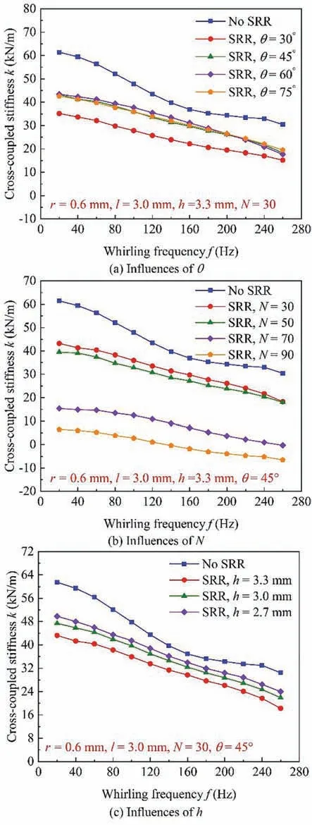
Fig. 12 Cross-coupled stiffness k vs whirling frequencies f.
Fig.13 displays the influences of the θ,N,and h of SRR on cross-coupled damping c. As described in Fig. 13, we can see that c is negative at all studied conditions, and the c gradually increases with the growth of frequencies. As can be seen in Figs. 13(a) and 13(b), the magnitude of the cross-coupled damping would significantly decrease at 20-260 Hz with the increase of θ and N for the honeycomb seal with SRR. However, as shown in Fig. 13(c), the increase of h significantly decreases the magnitude of c for f<160 Hz,while there were few effects on c for f > 160 Hz.
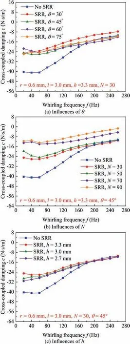
Fig. 13 Influences of θ, N, and h of SRR on cross-coupled damping c.
Fig.14 portrays the influences of the θ,N,and h of SRR on effective stiffness K.For all the studied conditions,Kgradually transforms from negative to positive with the growing f.Moreover, as displayed in Fig. 14, the varying θ, N, and h would slightly increase K. Overall, the honeycomb seal with SRR would increase the Kof the honeycomb seal to some extent.
Fig. 15 shows the influences of the θ, N, and h of SRR on effective damping C.The honeycomb seal without SRR produces a crossover frequency f, which means that the honeycomb seal would be unstable for f < f. However, all the Cis positive when SRR is introduced at the honeycomb seal entrance. This phenomenon proves that the effectiveness of SRR to enhance the stability of the rotor-bearing-seal system.Moreover,SRR with a smaller θ possesses a higher Cat 20-260 Hz. The numerical results also suggest that the Ccould be further improved with the increasing N and h.
3.4.Effects of SRR on flow-induced force acting on rotor surface
Fig. 16 describes radial force Fand tangential force Facting on the rotor surface for the x-direction excitation.The positive Fand Fmean its direction agrees with the direction of whirling displacement and velocity of the rotor, while the negative Fand Fare just contrary to the positive Fand F.As shown in Fig. 16(a), the Fis negative except for t = 0.075 s. As displayed in Fig. 16, the numerical results show that the honeycomb seal with SRR would significantly increase the magnitude of the negative F. Therefore, the forward whirling velocity would be weakened.This phenomenon would be conducive to improve the stability of the rotor. However, as shown in Figs. 16(c), and 16(d), compared the results with the case of θ=30°,another interesting observation is that the absolute of Ffor the case of θ=45°,75°are significantly less than the case of θ = 30°. This phenomenon discloses that a larger bending angle will weaken the ability of SRR to enhance the negative F. Besides, as shown in Figs. 16(c),16(e), and 16(f), we can also see that the absolute of negative Fand Fshows a significant increase when SRR possesses a higher N and h.This result shows that a higher N and h is beneficial to enhance the performance of SRR.
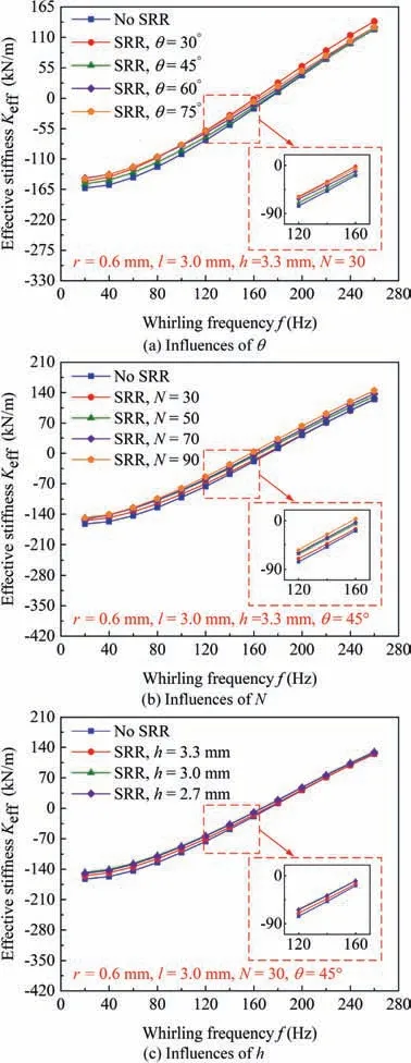
Fig. 14 Influences of θ, N, and h of SRR on effective stiffness Keff.
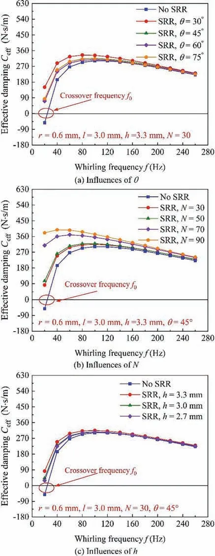
Fig. 15 Influences of θ, N, and h of SRR on effective damping Ceff.
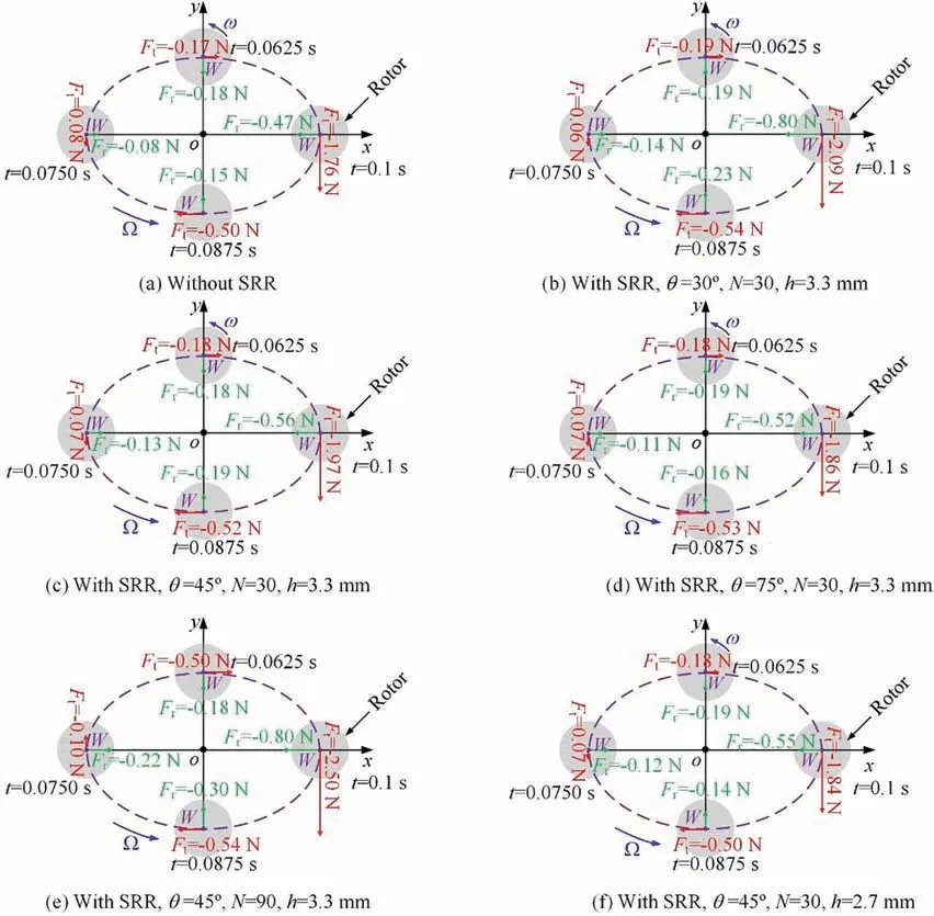
Fig. 16 Radial force Fr and tangential force Ft acting on rotor surface at x-direction excitation.
3.5. Effects of SRR on circumferential pressure distribution
Fig.17 gives the circumferential pressure cloud distribution of the x-direction excitation.The honeycomb seal with SRR possesses a narrow high-pressure area and a wider low-pressure area. Therefore, the changes in the position of relatively high and low pressures would lead to the difference in the value and direction of Fand F.Overall,the numerical results show that the honeycomb seal with SRR is beneficial to improve the uneven distribution of circumferential pressure. This will significantly enhance the stability of the rotor.
4. Conclusions
The honeycomb seal is a crucial component to restrict the leakage flow and improve the system stability for the turbomachines and aero-engines. In this work, the approach of computational fluid dynamics was adopted to investigate the leakage and rotordynamic characteristics for the honeycomb seal with SRR.The effects of bending angle,arrangement density,and height of SRR were analyzed.Several conclusions can be summarized as follows.
(1) The circumferential velocity at the seal entrance can be effectively weakened when SRR is introduced. Meanwhile, the ability to weaken the circumferential velocity can be further enhanced when SRR possesses a smaller bending angle, a higher arrangement density, and height.
(2) The honeycomb seal with SRR would improve the flow patterns at the seal entrance and strengthen the eddy dissipation effect in the seal cavity.Therefore,the seal with SRR possesses a lower leakage flow rate.
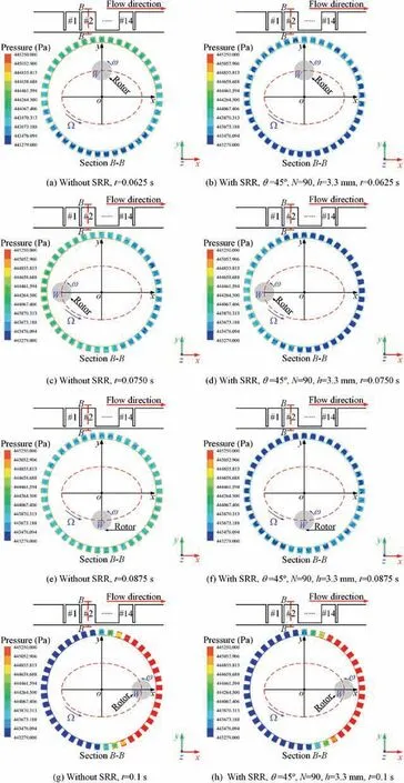
Fig. 17 Circumferential pressure cloud distribution at x-direction excitation.
(3) The honeycomb seal with SRR has little effect on the direct stiffness, direct damping, and effective stiffness of the honeycomb seal. However, SRR will significantly decrease the cross-coupled stiffness and improve the effective damping of the honeycomb seal. Moreover,SRR possesses a smaller bending angle, a higher arrangement density, and height will further reduce the cross-coupled stiffness and improve the effective damping. This is beneficial to improve the performance of SRR.
(4) The absolute value of negative tangential force would be significantly enhanced when SRR is introduced.Therefore, the whirling velocity of the rotor could be weakened. Besides, the honeycomb seal with SRR will significantly improve the circumferential pressure distribution in the seal cavity, which will be beneficial to enhance the rotordynamic stability of the rotor.
The authors declare that they have no known competing financial interests or personal relationships that could have appeared to influence the work reported in this paper.
The author thanks the anonymous reviewers for their critical and constructive review of the manuscript. This study was co-supported by the National Natural Science Foundation of China (No.51875361) and the Natural Science Foundation of Shanghai, China (No.20ZR1439200).
 Chinese Journal of Aeronautics2022年6期
- Chinese Journal of Aeronautics的其它文章
- Experimental investigation of a gliding discharge plasma jet igniter
- Evolution of turbulent boundary layer over a three-dimensional bump
- Conceptual design and preliminary experiment of icing risk management and protection system
- Direct thrust control for multivariable turbofan engine based on affine linear parameter-varying approach
- Characteristics of reattached boundary layer in shock wave and turbulent boundary layer interaction
- Structurally coupled characteristics of rotor blade using new rigid-flexible dynamic model based on geometrically exact formulation
