A compressing and saving method for structured grid data based on block construction
Yan SUN, Ying ZHAO, Dehong MENG,*, Meng JIANG
a State Key Laboratory of Aerodynamics, China Aerodynamics Research and Development Center, Mianyang 621000, China
b Computational Aerodynamics Institute, China Aerodynamics Research and Development Center, Mianyang 621000, China
KEYWORDS CFD;Compression;Compression ratio;Structured grid;Transfinite interpolation
Abstract The increasing grid data in CFD simulation has brought some new difficulties and challenges,such as high storage cost,low transmission efficiency.In order to overcome these problems,a novel method for compressing and saving the structured grid are proposed.In the present method,the geometric coordinates of the six logical domains of one grid block is saved instead of all grid vertex coordinates to reduce the size of the structured grid file when the grid is compressed. And all grid vertex coordinates are recovered from the compressed data with the use of the transfinite interpolation algorithm when the grid is decompressed.Firstly,single-block grid cases with different edge vertexes are tested to investigate the compression effect. The test results show that a higher compression ratio will be obtained on a larger grid.Secondly,further theoretical analysis is carried out to investigate the effects of parameters on grid compression. The analysis on single-block grid compression shows that the compression ratio is proportionate to the cubic root of the number of total vertexes. The highest compression ratio of single-block grid is obtained when the numbers of vertexes in three logical directions are equal. The analysis on multi-block grid compression shows that a higher compression ratio will be obtained when a larger difference of total vertexes number exists among the grid blocks.Finally,multi-blockgrids of two industrial aircraft configurations are compressed to validate the method. The compression results demonstrate that the present method has an excellent ability on structured grid compression. For a million-vertex structured grid, more than 80 percent disk space can be saved after compression.
1. Introduction
The simulation capabilities of Computational Fluid Dynamics(CFD) have been increasingly improved with the rapid development of computer technology and parallel computing algorithm.Now CFD has become an important simulation tool in design and performance evaluation of aerospace vehicles,which can support the design optimization and the performance improvement for different aircraft by providing highprecision complex flow simulation data.
In CFD simulation, the partial differential flow governing equations are discretized via the computational grid and transformed into algebraic equations. Then these flow variables(such as density, pressure, temperature, etc.) are obtained by solving the algebraic equations and the performance characteristics of the aircraft can be calculated through integration on the solid surface grid.Therefore, the computational grid plays a fundamental role in the CFD numerical simulation, a key factor in numerical analysis prediction accuracy and efficiency.
According to the connection between the grid vertexes, the CFD computational grid can be classified into two categories:structured grid and unstructured grid.The number of adjacent vertexes of internal grid vertex keeps constant in the structured grid while the number is variable in the unstructured grid.The structured grid has been widely used in CFD simulation due to its simple connection relationship, high resolution, and superior grid quality.
The main storage formats of the structured grid in CFD are Gridgen,Plot3D,CGNS,and Tecplot,including both text and binary format These storage formats save the geometric coordinates of all grid vertexes.Then the size of the grid file will be very large when the number of total vertexes is high.To obtain high-precision simulation results around complex configurations, CFD needs to use large-scale grids to capture the small flow features.So,the current storage formats of the structured grid will cause some new challenges in the CFD numerical simulation, such as high storage cost, low transmission efficiency.For example, a single-block structured grid with 10 million vertexes will use about 228 Mb disk space in doubleprecision Plot3D binary format and 700 Mb disk space in double-precision Plot3D ascii format. Moreover, in aerodynamic shape optimization, unsteady flow simulation or load analysis, there are a great number of simulation cases where grids of different configurations are used. As a result, numerous large grid files will significantly increase the access to the disks and speed the aging of the hardware,which will increase the probability of data corruption and may cause some irretrievable results. Thus, it has potential application value to develop compression method and storage format for the structured grid in reducing storage cost, increasing transmission efficiency and accelerating grid data reading.
Currently, the grid data compression is mainly used on the unstructured triangular mesh in the area of computer graphics and visualization. The compression method is separated into two types: topology-driven compressionand geometrydriven compression.However, there is no compression method for the structured grid in CFD simulation according to the authors’ knowledge.
In the topology-driven compression method, the redundancy information of the connections between the grid vertexes is used to encode the grid topology data and reduce the size of the grid file.However,the topology information of grid vertex connection is involved in the rank of the grid vertexes in the structured grid. It is unnecessary to explicitly define and save the topology information for the structured grid. So,the topology-driven compression method is not suitable for the structured grid.
The geometry-driven compression method can obtain a higher compression rate by encoding the geometric data. But it is usually a kind of lossy compression, which may lose geometric precision.The method can provide enough precision for visualization in the area of computer graphics.However,in the area of numerical simulation which requires high surface precision of configurations, such as CFD, the geometry-driven compression method may cause great uncertainty to the numerical simulation results.
Therefore, a compression and saving method for the structured grid based on block construction is proposed to meet the need of grid compression in CFD numerical simulation. The proposed method is inspired by the transfinite interpolation algorithm widely used in the structured grid generation and authors’ grid generation experience during the past fifteen years.When the grid is compressed,the geometric coordinates of the six logical domains of the grid block are saved instead of all grid vertex coordinates to reduce the size of the structured grid file. When the grid is decompressed, all grid vertex coordinates are decoded and recovered from the compressed data with the transfinite interpolation algorithm.
There are six sections in this paper. A detailed description of the present compression method is given in Section 2.Single-block grid cases with different edge vertexes are tested in Section 3. Theoretical analysis on single-block and multiblock grid compression is carried out in Section 4. The compression validation of multi-block grids of two industrial aircraft configurations is presented in Section 5. The conclusions of the paper are given in Section 6.
2. Compressing and saving method
2.1. Structured grid compression method
Several classical methods for generating the structured grid have been developed in the past decades, such as conformal mapping,algebraic interpolationpartial differential equationsand so on. The Transfinite Interpolation(TFI), a typical algebraic interpolation method, has been widely used in multi-block structured grid generation due to high quality and efficiency in the past three decades. The TFI has become the standard algorithm for the structured grid generation in some famous commercial software,such as Pointwise, Ansys ICEMCFD.
There are two construction levels in the TFI algorithm.One is the surface or domain construction and the other is the volume or block construction.The surface or domain grid is constructed by the interpolation of the vertex coordinates on the four edges which are the domain boundaries.Then the volume or block grid is constructed by the interpolation of the vertex coordinates on the six domains which are the block boundaries. The details of the TFI algorithm can be found in literatures.
The composition sketch of a single-block structured grid is shown in Fig.1.There are twelve edges and six faces in the grid block. The six faces (face, face, face, face, face, and face) are located in the three logical directions (i, j, and k).Based on the block construction of the TFI algorithm, the entire vertex coordinates of the block can be uniquely determined by the vertex coordinates on the six faces. Therefore,the geometric information of the grid block can be described only by the vertex coordinates of the six faces, which lays the theoretical foundation for the structured grid compression and saving method in this paper.
The idea of the compressing method is to save the vertex coordinates on the six faces instead of the entire vertex coordinates of the block to reduce the size of the grid file. And the total vertex coordinates are recovered from the compressed data by the TFI algorithm when the grid file is decompressed.
2.2. Compression procedure
The steps of the structured grid compression method are introduced in this subsection. Firstly, the number of the grid vertexes (n, nand n) in each logical direction (i, j and k) is extracted from the grid file or the computer memory.Secondly,the entire vertex coordinates xyz(1:3,1:n,1:n,1:n)of the grid block are read from the grid file or the computer memory.Thirdly,the vertex coordinates of the six faces of the grid block xyz(1:3,1:n,1:n), xyz(1:3,1:n,1:n), xyz(1:3,1:n,1:n),xyz(1:3,1:n,1:n), xyz(1:3,1:n,1:n), xyz(1:3,1:n,1:n) are extracted from the xyz(1:3, 1:n, 1:n, 1:n). The coordinates extraction is defined as following:
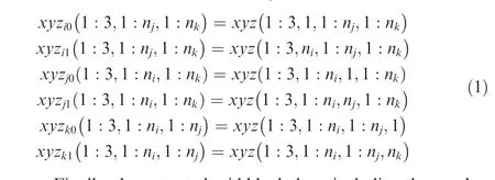
Finally,the extracted grid block data,including the number of the grid vertexes in each logical direction(n,nand n)and the vertex coordinates of the six faces xyz(1:3,1:n,1:n),xyz(1:3,1:n,1:n), xyz(1:3,1:n,1:n), xyz(1:3,1:n,1:n),xyz(1:3,1:n,1:n), xyz(1:3,1:n1:n), is saved to the compressed grid file. For a multi-block grid, the steps above are executed iteratively to compress each grid block.
2.3. Decompression procedure
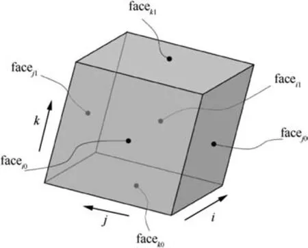
Fig. 1 Sketch of single-block structured grid.
The decompression procedure of the structured grid is just opposite to the compression. Firstly, the compressed grid block data, including the number of the grid vertexes in each logical direction (n, nand n) and the vertex coordinates of the six faces xyz(1:3,1:n,1:n),xyz(1:3,1:n,1:n),xyz(1:3,1:n,1:n),xyz(1:3,1:n,1:n),xyz(1:3,1:n,1:n),xyz(1:3,1:n,1:n), is read from the compressed grid file. Secondly, the entire vertex coordinates xyz(1:3,1:n, 1:n,1:n) of the grid block are recovered from the compressed block grid data by the volume construction of the TFI algorithm. For a multi-block structured grid, the two steps above are executed repeatedly to recover each grid block data. After decompression, the entire recovered grid data can be exported to a grid file in a specified format.
3. Single-block grid compression test
The compression effects, such as the size reduction of the grid file,compression ratio and compression efficiency,are the ability indicators of the grid compression methods.In this section,the compression effect of the present method on the singleblock structured grid is tested and investigated.This test is performed in the grdZip V1.0, the multi-block structured grid compression program which is independently developed by the Institute of Computational Aerodynamics, China Aerodynamics Research and Development Center.
Fig. 2 shows the test cases, three single-block structured grid with different number of grid vertexes. The Case 1 is a cube-shape structured grid, in which the numbers of the grid vertexes in three logical directions are the same and equal to N. The Case 2 is a block-shape structured grid, in which the numbers of the grid vertexes in three logical directions is 2N, N, N, respectively. The Case 3 is a block-shape structured grid, in which the numbers of the grid vertexes in three logical directions are 2N, N, N/2, respectively. The range of Nis from 25 to 800 in the test.
Fig.3 shows the compression ratio of the three single-block structured grids with a different number of vertexes.The variable λ in Fig. 3 represents the compression ratio, which is defined by the ratio between the original grid size and the compressed grid size. In this paper, the original grid file uses a double-precision binary plot3d format to save the grid data while the compressed grid file with a double-precision binary format. The variable Nrepresents the number of vertexes on the grid edge and the variable Nrepresents the total number of the grid vertexes. Fig. 3(a) shows the change of the grid compression ratio λ with different Nand Fig. 3(b)shows the variation of the grid compression ratio λ with different N.
As shown in Fig. 3(a), the compression ratio λ varies linearly with the number of vertexes on grid edge Nin all three test cases.A larger Nwill obtain a higher λ which indicates a better compression. For a fixed N, the Case 2 obtains the highest compression ratio λ,the Case 3 the lowest and the Case 1 in-between. The compression ratio λ increases nonlinearly with the increase of the total number of grid vertexes Nin all three test cases and a larger Nwill get a higher λ as well as better compression, as shown in Fig. 3(b). In fact, the increase rate of λ decreases gradually with the increase of Ndue to a logarithmic coordinate used for the variable Nin Fig. 3(b).
For a given N, the Case1 gets the highest compression ratio, the Case 3 the lowest and the Case 2 in-between. For a single-block structured grid with one million vertexes,the compression ratios of the three test cases are approximately equal to 16.7,15.9 and 14.3,respectively.For a grid with ten million vertexes, the compression ratios of the three test cases are approximately equal to 35.9, 34.2 and 30.8, respectively. For a grid with one hundred million vertexes, the compression ratios of the three test cases are approximately equal to 77.4,73.7 and 66.3, respectively.
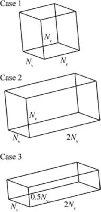
Fig. 2 Single-block grid compression cases.
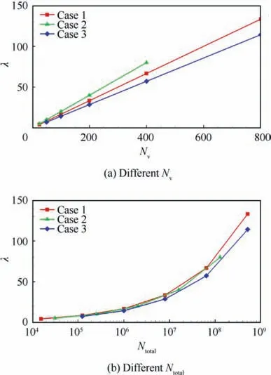
Fig. 3 Compression ratio of three single-block structured grids.
4. Theoretical analysis on structured grid compression
In this section, further theoretical analysis on the structured grid compression is carried out to investigate the compression effect on a more general grid.Firstly,a single-block structured grid with variable vertexes on the grid edges is used to analyze the parameters influence on the compression ratio. Then the multi-block structured grid compression is analyzed and discussed based on the single-block analysis results.
4.1. Analysis of single-block structured grid compression
Fig.4 shows the single-block structured grid case with variable vertexes on the grid edges. The numbers of grid vertexes in three logical directions are set as N, αNand βN, as shown in Fig. 4 The α and β are the variable factors used to adjust the number of vertexes on the grid edges.In factor,the choice of the logical direction in which the number of grid vertexes is set as Nhas no impact on the analysis results of the final compression effect, which will also be validated in the following subsection.As a result,it aims to keep consistent with Section 3 that the number of vertexes in j direction is set as Nwhile the numbers of vertexes in i and k direction are set as αNand βN.The number of the total grid vertexes on the six logical faces of the grid block is defined as N. The number of the total grid vertexes of the grid block is defined as N. The Nand Ncan be calculated respectively by the following equations:
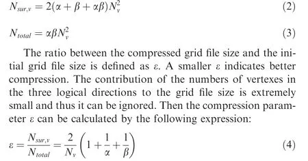
From Eq.(4),it can be found that the ε is inversely proportional to the N. When the factors α and β are determined, a larger Nwill obtain a smaller ε value and better grid compression.
The compression ratio λ, the reciprocal of the ε, is derived from Eq. (4) as

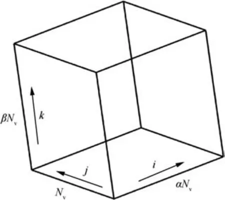
Fig.4 Single-block structured grid with variable vertexes on grid edges.
The λ is linearly proportional to the number Nwhen the factors α and β are given, which is consistent with the test results of the single-block grid case in Fig. 3.
Define
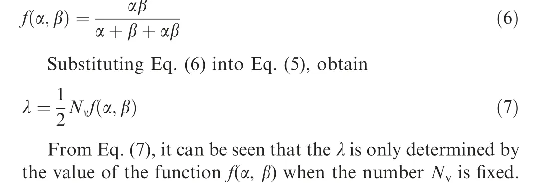
Fig. 5 shows the value of the f(α, β) function at different α and β,in which the f(α,β)contour at different α and β is shown in Fig.5(a)and the f(α,β)vs β curves at different α are plotted in Fig. 5(b).
In Fig. 5, the value of the function f(α, β) distributes symmetrically in the (α, β)plane and the axis of symmetry is right the straight line of α=β.The symmetrical characteristic of the function f(α,β)illustrates that α and β playthe same role in the calculation of the function f(α,β).It means that exchanging the α and β will not change the value of the function f(α,β),which further demonstrates that the grid compression ratio is independent of the choice of the logical direction.
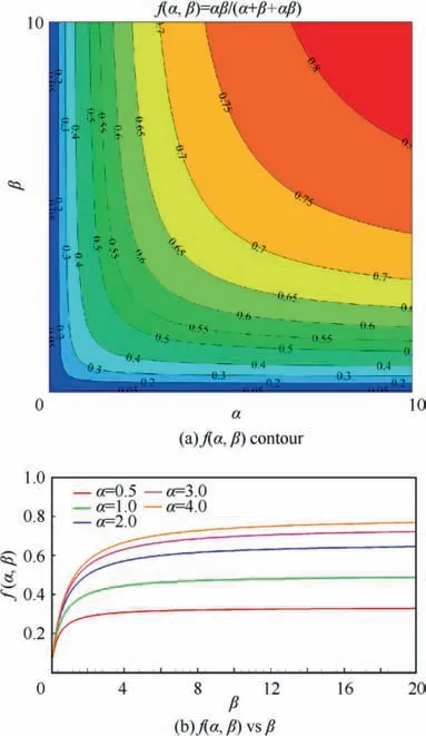
Fig. 5 Value of function f(α, β) at different α and β.
At different α,the value of the function f(α,β)increases as β increases, but the increase rate decreases quickly, as shown in Fig. 5(a). When the α and β go to infinity, the f (α, β) will obtain a limit value of 1.0 and the compression ratio λ will tend to N/2.In this limit situation,the number of the grid vertexes on the boundary face in the j direction Nis far beyond that in the other two logical directions (i and k). As a result,the number of total grid vertexes on the six boundary faces of the grid block is approximated to 2N. The entire grid block consists of Nsame faces in j direction and the number of total grid vertexes of the grid block is NN. Thus, the limit of the compression ratio λ is equal to N/2.
From Eq. (3), the Ncan be derived as:
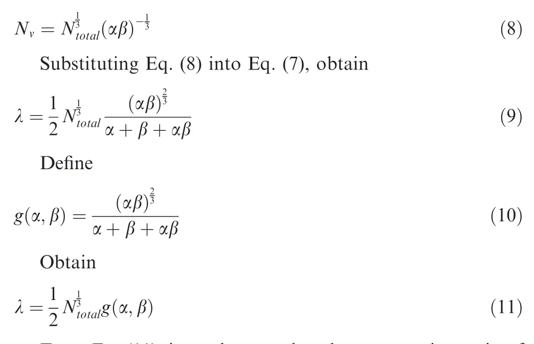
From Eq. (11),it can be seen that the compression ratio of the single-block structured grid is proportionate to the cubic root of the number of the total grid vertexes N. The compression ratio λ is uniquely determined by the value of the function g(α,β)when the Nis given.Fig.6 shows the value of the g(α,β)function at different α and β,in which the g(α,β)contour at different α and β is shown in Fig. 6(a) and the g(α,β) vs β curves at different α are plotted in Fig. 6(b).
Same to the function f(α, β), the function g(α, β) also distributes symmetrically in the (α, β) plane and the axis of the symmetry is the line of the α = β, as shown in Fig. 6(a). It means that the exchange of the α and β has no influence on the value of the g(α,β).At different α,the g(α,β)first increases rapidly to the maximum value and then decreases slowly as β increases, as shown in Fig. 6(b). The function g(α, β) gets its maximum value of 1/3 when α and β are both equal to 1.0.It can be concluded that the maximum compression ratio of a single-block structured grid of which the number of total grid vertexes Nis given will be obtained when the numbers of the grid vertexes in three logical directions are the same.
The maximum compression ratio is defined as the ideal compression ratio λ. The λis expressed as

In Eq. (12), the Nis the normalized number of vertexes on grid edge,which is equal to the cubic root of the number of total grid vertexes N.
4.2. Analysis of multi-block structured grid compression
It is extremely hard to discretize a complex flow region with a single-block structured grid. In flow simulation on complex industrial configurations,multi-block structured grids are usually used to divide the computational region into many connected grid zones, which are called blocks. The volume construction of the TFI algorithm is used to generate the grid vertexes in each block and then all blocks are assembled as a whole grid for the discretization.
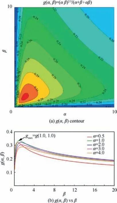
Fig. 6 Value of function g(α, β) at different α and β.
In this subsection, the multi-blockgrid compression is analyzed.Since the different blocks are independent on each other,the multi-block structured grid can be compressed through the compression of each grid block data gradually,which has been analyzed detailedly in Subsection 4.1.
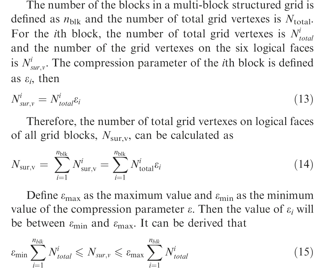
Besides, the number of total grid vertexes Ncan be calculated by the sum of the number of total grid vertexes in each block, expressed as
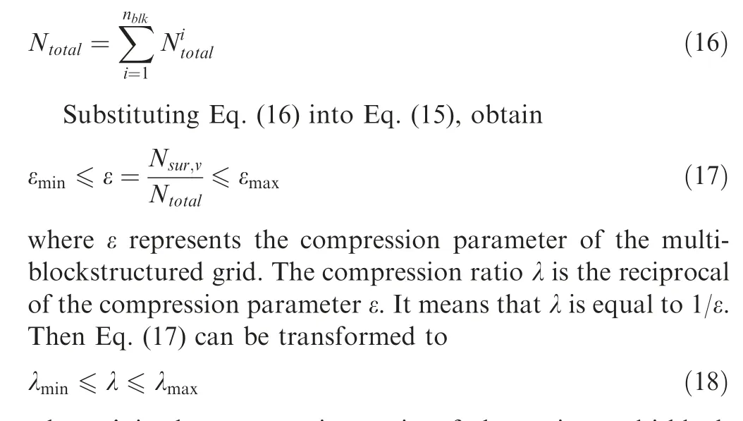
where λ is the compression ratio of the entire multi-block structured grid.The λis equal to 1/εand is the minimum compression ratio of all nblocks.The λis equal to 1/εand is the maximum compression ratio of all nblocks. Eq.(18) shows that the compression ratio of the entire multiblock structured grid is just between the maximum and minimum value of the compression ratio of all single blocks in the multi-block grid.
From the analysis in Subsection 4.1, the compression ratio of single-block grid is proportionate to the cubic root of the number of total grid vertexes. The number of total grid vertexes of single block will decrease when the number of grid blocks nincreases for a multi-block structured grid of which the number of total grid vertexes Nis given.As a result,the compression ratio of the entire multi-block grid will decrease when the grid is divided into more blocks without increasing the number of the vertexes.
From Eq.(11),the compression ratio of the ith block of the multi-block grid λis calculated as
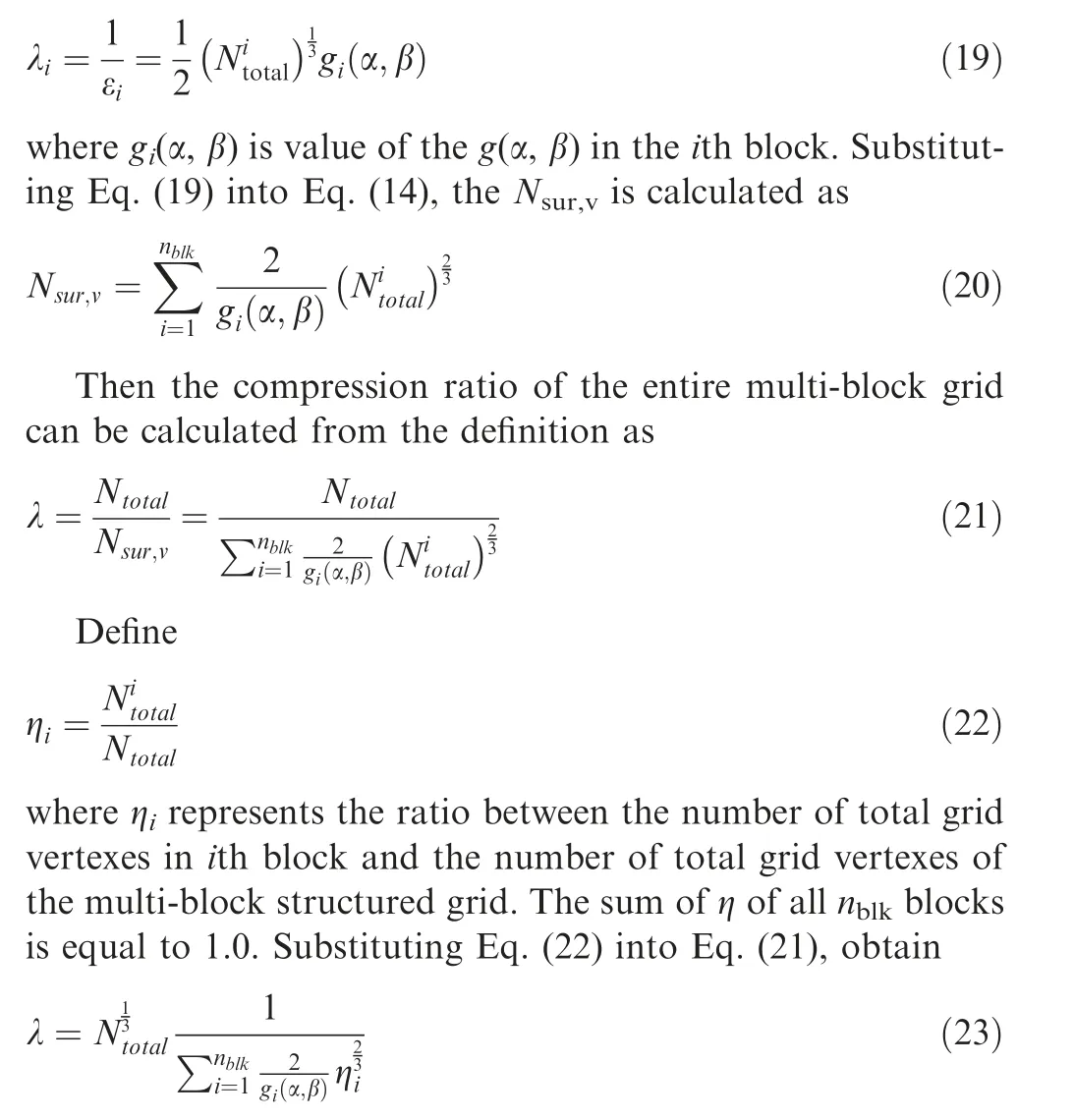
In an assumption that the factors α and β are not far away 1.0 in each block of the multi-block structured grid, the function g(α, β) of the ith block is approximate to the maximum value of 1/3. Substituting g(α, β)≈1/3 into Eq.(23), the compression ration λ is calculated as
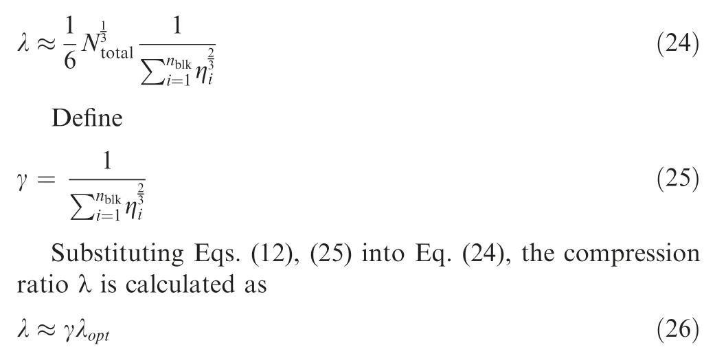
The Eq.(26)shows that the compression ratio of the multiblockstructured grid is approximate to the product of the ideal compression ratio λand the coefficient γ.The λis exactly determined by the number of total grid vertexes of the multiblock grid N, so the compression ratio is uniquely determined by the value of coefficient γ for a multi-block grid of which the Nis given.
If the number of total grid vertexes in each block is the same, the ratio η in each block will be constant and equal to 1/n. Then the coefficient γ is derived from Eq. (25) as

Therefore, the compression ratio of the multi-block structured grid, in which the number of total grid vertexes in each block does not differ too much, can be estimated quickly by Eq.(28)with the number of total grid vertexes and the number of the blocks.
Fig.7 shows the value of coefficient γ under different η distributions in a multi-block structured grid case in which the number of grid blocks nis selected as 100.In Fig.7,the ordinate axis represents the product of η and nwhile the abscissa axis represents the block index ib. There are four linear distributions and three nonlinear distributions (quadratic, cubic,exponential) of the coefficient η. The constraint that the sum of η in each block is equal to 1.0 is satisfied for all distributions.
When the coefficient η distributes uniformly in all grid blocks, the coefficient γ obtains the minimum value of 0.2154 which is equal to the reciprocal of the cubic root of n,shown as the ‘Linear 01case in Fig. 7. As the heterogeneity of the η distribution increases, the value of coefficient γ grows slowly.In the nonlinear ‘Cubic’ case, the coefficient γ reaches a maximum value of 0.2561, about 18.9% relative increase to the‘Linear 01case.
Fig.7 illustrates that a higher compression ratio and better compression effect will be achieved for a multi-block structured grid of which the number of total grid vertexes is given when the difference between the maximum and minimum value of the number of total vertexes in each block is much larger.In contrast,a higher compression ratio of the multi-block structured grid will be obtained when the number of total vertexes in each block distributes more uniformly.
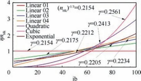
Fig. 7 γ value with different η distributions (nblk = 100).
From the derivation, The value of the compression ration of the multi-block structured grid in Eq. (28) is based on two assumptions. One is that the function g(α, β) uses the maximum value of 1/3 and the other is that the number of total grid vertexes in each block distributes uniformly. Based on the analysis in Subsection 4.1 and this subsection, the former assumption will overestimate the value of the compression ratio λ while the latter assumption will underestimate the λ.As a result, the influence of the two assumptions is counteracted by each other and the estimation in Eq.(28)may predict an approximate compression ratio value for a multi-block structured grid.
5. Grid compression applications
In this section, the present method is validated through the multi-block structured grid compression of two industrial configurations. One configuration is the DLR-F6-WB model and the other is the NASA-CRM-WBNP model.
5.1. DLR-F6-WB configuration
DLR-F6 is a twin-engine aircraft configuration designed by the German Aerospace Research Institute DLR in the 1980s and represents a class of modern wide-body transport aircraft.Since the DLR-F6 model was tested in many world-class wind tunnel facilities and plenty of different test data was measured, this configuration has been selected as the benchmark case in the second and third AIAA Drag Prediction Workshop (DPW) to validate the prediction accuracy and evaluate the state of the art of the CFD software all over the world.
Fig. 8 shows the shape and the multi-block structured grid topology of the DLR-F6-WB configuration.The whole model of DLR-F6-WB is shown in Fig.8,but only the grid of the half model is used for the compression.
There are 106 blocks,2,656,378 vertexes and 2,402,304 hexahedron cells in the multi-block structured grid of the half DLR-F6-WB model. The minimum number of the total grid vertexes in each block is 1377 while the maximum number is 293625.
Fig. 9 shows the compression ratio in each block of the DLR-F6-WB grid. In Fig. 9, the abscissa axis represents the block index and the ordinate axis represents the compression ratio of each block. Besides, the three legend symbols‘Single-block opt’,‘Single-block real’,‘Multi-block real’represent the ideal compression ratio of single block, the actual compression ratio of single block and the real compression ratio of the multi-block grid, respectively.
Compared with the ideal compression ratio of each block,the real compression ratio of each block is a little lower but the difference is small for most blocks,as shown in Fig.9.The highest compression ratio of each block is about 9.0 and the lowest is approximately 2.0. The compression ratio of the multi-blockgrid is about 5.05, which is between the highest and lowest compression ratio of each block. The compression ratio of the multi-block grid estimated by Eq. (28) is about 4.88, which is very close to the real value of 5.05.
The original grid file of the DLR-F6-WB grid stored in double-precision Plot3D binary format uses 60.8 Mb disk space while the compressed grid file in double-precision binary format only occupies about 12.03 Mb disk space.The original file size in double-precision Plot3D ascii format is 186 Mb while the compressed file size in double-precision ascii format is 36.7 Mb.It will save up to 80.21%disk space after compression for the multi-block structured grid of the DLR-F6-WB model.
5.2. NASA-CRM-WBNP configuration
Common Research Model (CRM) was sponsored by NASA’s Subsonic Fixed Wing (SFW) project to evaluate and improve the state of the art of CFD software all over the world with high-quality test data. The NASA-CRM is a wing-bodynacelle-pylon-tail model, of which the aerodynamic characteristics were designed by the Boeing company. Then NASA designed and manufactured the model structure and tested the model in some world-class wind tunnel facilities, such as NTF,ETW.The NASA-CRM has been selected as the benchmark case in the 4th, 5th and 6th AIAA Drag Prediction Workshop (DPW).
Fig.10 shows the shape and the multi-block structured grid topology of the NASA-CRM-WBNP configuration. The whole model of NASA-CRM-WBNP is shown in Fig. 10,but only the grid of the half model is used for the compression.There are 153 blocks, 12,087,897 vertexes and 11,287,296 hexahedron cells in the multi-block structured grid of the half NASA-CRM-WBNP model. The minimum number of the total grid vertexes in each block is 3367 while the maximum number is 1577497.
Fig. 11 shows the compression ratio in each block of the NASA-CRM-WBNP grid. The symbols in Fig. 11 are the same as those in Fig. 9. The highest ideal compression ratio of each block is about 19.0 and the lowest is about 2.0. The highest real compression ratio of each block is about 13.0 and the lowest is about 2.0. The compression ratio of the multi-block grid is 7.38, which is very close to the estimation value of 7.15 by the Eq. (28).
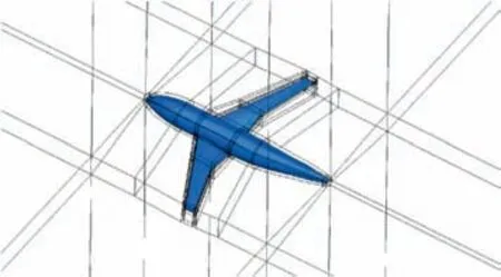
Fig. 8 Shape and grid topology of DLR-F6-WB model.
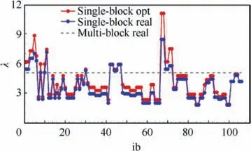
Fig. 9 Compression ratio in each block of DLR-F6-WB grid.
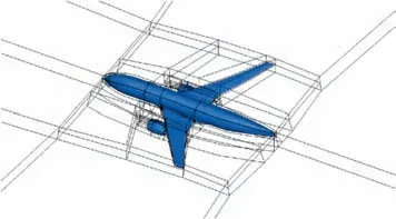
Fig. 10 Shape and grid topology of NASA-CRM-WBNP model.
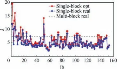
Fig. 11 Compression ratio in each block of NASA-CRMWBNP model.
The original grid file of the NASA-CRM-WBNP grid stored in double-precision Plot3D binary format uses 276 Mb disk space while the compressed grid file in doubleprecision binary format only occupies about 37.4 Mb disk space. The original file size in double-precision Plot3D ascii format is 847 Mb while the compressed file size in doubleprecision ascii format is 114.7 Mb. It will save up to 86.45%disk space after compression for the multi-block structured grid of the NASA-CRM-WBNP model.
If the number of the grid vertexes on each edge of the NASA-CRM-WBNP grid is doubled,the number of total grid vertexes will be enlarged eight times and reach to 96.7 million.Then the original grid file stored in double-precision binary Plot3d format will occupy about 2.11 Gb disk space while the compressed file only uses about 149.6 Mb disk space.The saving of disk storage is up to 93.22%.
The compression of the NASA-CRM-WBNP grid data with different vertexes demonstrates that better compression by the present method is obtained on a larger size of the grid.It also indicates that an obvious compression effect that the saving of disk space is more than 90 percent can be achieved when the number of total grid vertexes of the industrial configuration grid is more than hundreds of million.
6. Conclusions
Based on the status that the multi-blockstructured grid in industrial applications is mainly generated by the volume construction of the transfinite interpolation algorithm,a compression and saving method for structured grid data was proposed in this paper. The present method saves the geometric coordinates of the six logical domains of one grid block instead of all grid vertex coordinates. The compression effect is closely investigated from the case tests and theoretical analysis. And the multi-block structured grids of two industrial configurations are compressed to validate the method. From the tests,analysis and validation, some conclusions can be obtained as follow.
(1) The compression ratio of a single-block structured grid is proportional to the cubic root of the number of total grid vertexes when the ratio between the number of grid vertexes in three logical directions is determined. A larger grid will obtain a higher compression ratio and better compression.
(2) The compression ratio of a single-block grid of which the number of total vertexes is given is determined by the ratio between the number of grid vertexes in each logical direction. When the number of vertexes in each direction is the same, the compression ratio reaches the maximum value which is equal to the cubic root of the number of total vertexes dividing six.
(3) The compression ratio of the multi-block structured grid is between the minimum and maximum value of the compression ratio of each block.
(4) The compression ratio of the multi-block structured grid increases as the heterogeneity of the distribution of the number of total grid vertexes in each block grows. The compression ratio is the lowest when the number of total grid vertexes in each block is the same.
(5) The compression ratio of the multi-block structured grid can be estimated approximately by the number of total grid vertexes and the number of grid blocks.
(6) The present method shows excellent compression effect that it can save 80 to 95 percent of disk space in compressing multi-block structured grids of industrial configurations with millions to billions of vertexes.
The deep compression for structured grid will be investigated based on the face and block reconstruction to further improve the storage and transmission efficiency of the multiblock structured grid in our follow-up work.
The authors declare that they have no known competing financial interests or personal relationships that could have appeared to influence the work reported in this paper.
This research is supported by the National Numerical Windtunnel Project, China.
 Chinese Journal of Aeronautics2022年6期
- Chinese Journal of Aeronautics的其它文章
- Experimental investigation of a gliding discharge plasma jet igniter
- Evolution of turbulent boundary layer over a three-dimensional bump
- Conceptual design and preliminary experiment of icing risk management and protection system
- Direct thrust control for multivariable turbofan engine based on affine linear parameter-varying approach
- Characteristics of reattached boundary layer in shock wave and turbulent boundary layer interaction
- Structurally coupled characteristics of rotor blade using new rigid-flexible dynamic model based on geometrically exact formulation
