Effect of assisted transverse magnetic field on distortion behavior of thin-walled components in WEDM process
Ynming ZHANG ,Guojun ZHANG ,Zhen ZHANG ,Yi ZHANG ,Yu HUANG
a State Key Lab of Digital Manufacturing Equipment &Technology,School of Mechanical Science and Engineering,Huazhong University of Science and Technology,Wuhan 430074,China
b Department of Mechanical Engineering,Northwestern University,Evanston 60201,USA
c School of Aerospace Engineering,Huazhong University of Science and Technology,Wuhan 430074,China
d Guangdong HUST Industrial Technology Research Institute,Guangdong Provincial Key Laboratory of Digital Manufacturing Equipment,Dongguan 523808,China
KEYWORDS Distortion behavior;Distribution of discharge points;Thin-walled components;Transverse magnetic field;Wire electrical discharge machining
Abstract Machining performance of thin-walled components made by aeronautical difficult-toprocess materials is a significant issue in the aviation manufacturing industry.Although wire electric discharge machining-low speed (WEDM-LS) is one of typical non-contact machining processes without macro cutting force,which does well in removing hardness and brittleness materials via pulsed discharge at high temperature,but few researchers have studied the thermal distortion behavior leading to a considerable geometric error in the WEDM-LS of thin-walled components.In this paper,a transverse magnetic field assisted method is applied for affecting the uniformity of discharge point distribution so as to reduce the distortion in WEDM-LS processing thin-wall component.First,the generation mechanism of this new distortion behavior and the impact mechanism of transverse magnetic field(TMF)on distortion are demonstrated by theoretical analysis.In order to further figure out the distortion behavior in the TMF-WEDM process,a new thermophysical model considering the discharge point distribution is established to simulate temperature field,residual stress field and distortion profiles.Then a large number of Taguchi experiments are carried out to investigate the influences of process parameters including pulse discharge energy(pulse on time,pulse off time,and current)and magnetic field strength on distortion in WEDM-LS.To comparatively analyze simulated and experimental results,the accuracy of established thermophysical model is verified within a relative error of 18.38 % in distortion.Moreover,it can be revealed that transverse magnetic field contribute to significantly improve the longitudinal distribution uniformity with maximum increase of 12.32%at magnetic field strength:0.15 T,leading to significant reductions of 32.77% in distortion and 22.68% in recast layer.Eventually,we also presented the variation of residual stress and recast layer along thickness direction under different distortion behavior,which are in good agreement with that of distortion behavior.
1.Introduction
Thin-walled components of aeronautical difficult-to-process materials (like titanium,nickel-base alloys) are widely used in the key structures of aircrafts like rocket engine casings,aircraft landing gear,and aero-engine hollow shaft,and how to achieve the high quality of thin-walled components is a significant issue in the aviation manufacturing industry.But the large cutting force and severe chatter probably lead to poor machining performance and serious tool wear in traditional machining processes like cutting,turning,and milling of thin-walled components.Plenty of advanced non-contact machining technologies,such as electrochemical machining(ECM),laser machining,electrical discharge machining(EDM),etc.,are applied to fabricate thin-walled components of aeronautical difficult-to-process materials and improve their performance to satisfy the increasing requirements in precision manufacturing industries.Xu and Wangconducted a comprehensive review on the current developments,new trends,and technological advances of key factors in ECM process of complex components of aero-engines.With respect to complex shape structures (grooves,narrow slits,pillared structures,etc.),Ho et al.presented that WEDM had been widely used,e.g.,in the aerospace field,mold industry and medical apparatus and instrument manufacture since it possessed good features of non-contact machining,non-macro cutting force,precisely machining hard to process materials.The WEDMLS process exerts essentially no macro cutting force,leading to no significant cutting deformation,so the geometric error from the deformation would be extremely probably ignored.Whereas the thermal deformation from violently thermal erosion process is an extremely significant scenario in the WEDMLS process of thin-walled components.
Since WEDM causes thermally-induced residual tensile stresses on the machined surface,a destructive method is firstly proposed by Kruth et al.for measuring the residual stress at different depths beneath the machined surface.They have demonstrated the existence of considerable deformation phenomena in the rough WEDM of thin parts due to stress relaxation.Miller et al.focused studying the influences of WEDM parameters on surface features,microstructure properties,and debris of cross sections,and they revealed that the WEDM process of more complex shaped workpieces (like squares,reflectors) generated significant thermal deformation.In the end they also concluded the minimum thickness and compliant mechanisms of WEDM process.
The deformation of fins fabricated using micro-electrical discharge milling was studied by Zahiruddin and Kunieda,and the thermal and structural features of specimen’s deflection were analyzed via predicting the magnitude of residual stress and temperature distribution on their surfaces.They also pointed out that the non-uniform residual stress distribution could be one of the main reasons for thermal deformation behavior of electro machining.An experimental investigation was conducted by Zhang et al.to investigate the influences of main process parameters on thermal deformation behavior and microstructural characteristics of thin-walled samples in Inconel 718,AISIH13 and SKD11.Besides,Zhang et al.introduced and preliminarily analyzed more complicated but intriguing deformation scenario (distortion,deformation in two directions).Above brief literature reviews present that thermal deformation phenomena induced by the WEDM are considerable and complex,and that the discharge distribution and corresponding residual stress evolution on the thin-walled structures have closely related to their thermal deformation behavior.
To address issues caused by deformation and distortion behavior resulting in significant dimensional errors and bad surface integrity,it is urgent to figure out the complex deformation phenomena of WEDM processing thin-walled components and find appropriate strategies to reduce the deformation magnitude.Recently,Kimshowed that assisted magnetic field could contribute to a more uniform distribution of discharge points,shorten the formation time of plasma channels and reduce machining debris.Bains et al.concluded that the performance of WEDM process was indeed improved the machined surface quality and enhanced under the effect of magnetic field.Zhang et al.firstly comprehensive investigated the magnetic field assisted WEDM (MF-WEDM) process of nonmagnetic while Chen et al.further studied the mechanism and performance of MF-WEDM processing ferromagnetic materials.This technique could also simultaneously increase machining efficiency and surface quality.Wang et al.further studied the MF-WEDM process of thick shape memory alloy workpieces and confirmed that the distribution of discharging points becomes more uniform and reduces the number of broken electrode wires.Zhang et al.adopted transverse magnetic field assisted WEDM (TMF-WEDM) to improve the machining accuracy with reduction of thermal deformation and preliminarily revealed the effect of transverse magnetic field on the thermal deformation behavior.
According to the literature reviews,the conclusions can be drawn that the synergetic influence of magnetic field was successfully implemented in electrical discharge machining process to significantly enhance machining performance.The complicated deformation or even distortion behavior generated in thin-walled structure by WEDM-LS is a general and difficult issue.It is also evident that transverse magnetic field(TMF)assistance is probably a plausible method to relieve and solve this tough problem.However,few literature sources focus on discharge distribution and the corresponding residual stress evolution in conventional WEDM-LS and TMFWEDM processes of thin-walled components (like beams,sheets,fins,etc.),which are key requirements to completely explain the complex deformation(distortion)behavior considering the effects of non-assisted and assisted magnetic field.
The rest of this paper is arranged as below.Section 2 presents distortion mechanisms in WEDM processes of thinwall components.Section 3 analyzes the mechanism of assisting transverse magnetic fields on discharge point distribution,and then Section 4 establishes a thermo-physical model of the distortion variation to simulate the temperature and stress distribution on the machined surface.The experimental setup and procedure are introduced in Section 5.To investigate the effects of transverse magnetic field assistance on distortion behavior,experimental results and discussion are conducted in Section 6.At the end of this paper,the conclusions of this research are listed in Section 7.
2.Distortion mechanisms in WEDM of thin-wall components
According to our previous researches,deflections generated in thin-wall components by WEDM are a complex threedimensional problem.The diagram of the three-dimension deflection (in--plane) including the two-dimension deformation (in-plane) likes top deformation or bottom deformation and distortion phenomenon (inaxis) are displayed in Fig.1.Fig.1(a)shows that the diagram of distortion behavior in WEDM,which can be calculated from the difference in values of the top and bottom deformations as shown in Fig.1(b).
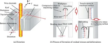
Fig.1 Diagram of three-dimensional deflection.
2.1.Mechanism of two-dimensional deformation
It is known that the residual stress is the most critical factor in the overall deformation of thin-walled parts while other factors such as cutting parameters,cutting path,cooling conditions,etc.,show indirect effects on deformation by changing the magnitude and distribution of the residual stress.Nonuniform heating and cooling cycles are a distinctive feature of WEDM processing which will generate non-uniform residual stress fields and then lead to complex strains consisting of thermal strains and plastic strains which are the main source of deformation.During the discharge process in WEDM,nonuniform expansion of the materials occurs due to the material inside the workpiece is allowed only to expand partially and then restrained leading to thermal stresses by the restraining action that prevents the material from freely expanding and contracting.The restraining actions will cause compressive and tensile stresses on the machined surface as shown in Fig.2.As shown in Fig.2,the stress in the machined surface of the first slit is tensile stress,when the machine begins to cut the second slit,the workpiece surface of the second slit is compressive stress in the local processing area,which means the stress of the sheet on the left and right surface is not balanced,and then the sheet begins to bend because its thickness is small enough (thin-wall component).With the continuous feeding of wire electrode,the thin-wall sheet continues to deform.After the machining process is finished,the deformation of the thin-wall sheet will complete after a certain time of stress balance.It’s worth to mention that Some of the material vaporized or removed will carry away some heat from the discharge area,and will,to some extent,reduce the gradient of uneven heat distribution.During the cooling process (no discharge spark),some material will recast into a recast layer on the machined surface and enlarge the gradient of the residual stress fields.It is worth noting that when the recast layer is in the liquid state,no stress exists due to the free state of the molten material.However,after it solidifies,the non-uniform cooling of the recast layer results in the formation of tensile stresses in the surrounding area.The machined features will keep on deforming until the residual stresses are balanced by the internal stresses in the material.Finally,plastic deformation forms and evolves through the WEDM process.
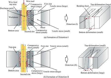
Fig.2 Process of formation of distortion I and distortion II.
Fig.1(b) reveals the residual stresses and deformation formation processes in WEDM.Compressive stresses (negative marks(-))are formed on the first machined surface,and after that tensile stresses (positive marks (+)) are generated and remain on the machined surface.An unbalanced stress distribution will appear due to the tensile stress on the machined surface after the 1st slot and compressive stress on the adjacent machined area after the 2nd slot.As displayed in Fig.1(b),the sheet begins to bend towards the 2nd slot until the residual stress reaches a new equilibrium state when the sheet width is thin enough (400 μm or less) and when the residual stress exceeds the yield strength.
2.2.Distortion mechanism
As displayed in Fig.1(a),the distortion value can be calculated from the difference of the top and bottom deformations as:

whereis the distortion of samples,is the top deformation of samples,andis the bottom deformation of samples.Eq.(1) implies that distortion is rooted in the non-uniform deformations along the workpiece’s thickness direction.
The following factors could contribute to the unevenness of deformation in thin-walled parts.
Discharge point distribution is the most crucial factor in affecting distortion of samples along the thickness direction.This is mainly due to the fact that the generation of distortions is attributed to the non-uniform residual stress distribution,which is determined by the discharge point distribution in WEDM.A larger number of discharge points in the machining area leads to higher heat transport,which often leads to higher temperatures and larger residual stresses under the same cooling conditions.As shown in Fig.2,when cooling conditions and other factors are the same,the distortion depends on the distribution of discharge points.When more discharge points concentrate at the top area compared with the bottom area,larger residual stresses and larger differences between tensile stresses in the 1st slot surface and compressive stresses in the 2nd slot surface occur.The above processes produce large top and small bottom deformations.The difference,to be referred to as distortion I (towards to 1st slot) is shown in Fig.2(a).On the contrary,when more discharge points are located at the bottom area,distortion II (towards to 2nd slot)will be generated due to small top and large bottom deformations as displayed in Fig.2(b).
The generation and values of the residual stresses also depend on the cooling process due to material re-solidifying into a recast layer which changes the residual stress fields.The cooling conditions include cooling time,cooling speed,cooling type (liquid coolant) and the properties of the material.The flow speed of deionized water and the temperature difference between the deionized water and the sample surface determine the cooling speed in WEDM.In WEDM of thin-wall components,the cooling time,liquid coolant,and material properties are homogeneous in the workpiece thickness direction.Therefore,a non-uniform cooling speed will contribute to an uneven recast layer thickness and residual stress distribution along the workpiece thickness direction.Higher cooling speeds lead to more solidified material,thicker recast layer and larger residual stresses.Larger cooling speed differences lead to larger gradients in the residual stress and distortions along the workpiece thickness direction.
The processing path has an important effect on the distribution of the stress fields because material removal is taking place at different positions under different processing paths and,consequently,leading to different stress accumulation sequences in the previously generated stress fields of the workpiece.Different stress accumulation histories produce distortions with different direction and magnitude.
3.Mechanism of transverse magnetic field assistance on distortion
According to the analysis in Section 2.2,discharge point distribution is the dominating factor that affects the distortion of samples along the thickness direction in WEDM.In this section the mechanism of transverse magnetic field assistance will be explored in terms of its ability to change and control the discharge point distribution,and then further reduce the distortion as shown in Fig.3.
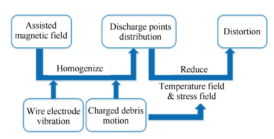
Fig.3 Influence mechanism of transverse magnetic field on distortion.
3.1.Mechanism of transverse magnetic field assistance on discharge point distribution
To reveal the influence mechanisms of transverse magnetic fields on discharge point distribution,the analysis of wire electrode vibration and charged debris motion is conducted in TMF-WEDM.
As we know,when the distance between the wire and workpiece is smaller than the discharge gap,discharges occur.This implies that the distribution and shift of discharge points have a close relation with the vibrations of the wire electrode.The fourth order partial differential equation of the wire electrode’s vibrations can be described by Guo et al.:

whereis the tension force of the wire,the elastic modulus,the moment of inertia of the wire geometry,ρthe density of the wire,andthe damping coefficient,() the external load due to sparks or excitation,()the wire position at location×and time.Further,the component of wire speed on wire vibration is also considered due to the vibration of electrode wire in this paper belongs to low frequency and large amplitude vibration.The vibration response of any point on the wire electrode in transverse magnetic field assisted WEDM-LS can be obtained as Eq.(3).
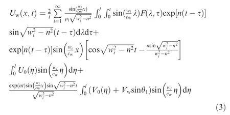
where(,)is the wire position at locationand time,is the distance between two guides,is the velocity of wave propagating on the string,ωis the natural circular frequency,is the frequency order,λ is the discharge point position,is the damping coefficient(-ζω),ζ is the damping factor,η is an integration variable,andare initial speed and initial position of discharge point in the wire,respectively,andis the wire speed,θis the wire deformation angle,(λ,τ)is the amplitude of the resultant force consisting of eight components including the tension force,Ampere force(induced by magnetic field),discharge force,electrostatic force,inviscid force,viscous force in the tangential directionand normal direction,water fluid force,and gravity force.The first component of Eq.(3)is the forced vibration component induced by the resultant force(λ,τ).To identify the mechanism of the transverse magnetic field on wire vibration and calculate the amplitude of the resultant force,the force analysis of the wire electrode in a transverse magnetic assisted WEDM must be implemented firstly as displayed in Fig.4.
It can be observed that the resultant force of(λ,τ) on the wire electrode is divided into two cases,i.e.,the forces above and below the discharge point as displayed in Fig.4(b).The electromagnetic force can be negligible compared to other forces.Sinceon wire under a transverse magnetic field is along theaxis,the transverse force analysis along theaxis is performed.The electrostatic force in theaxis direction is balanced by itself and has no effect on the transverse vibrations of the wire tool.Thus,the resultant force just includes the horizontal component of,,,,,,and,as expressed by:
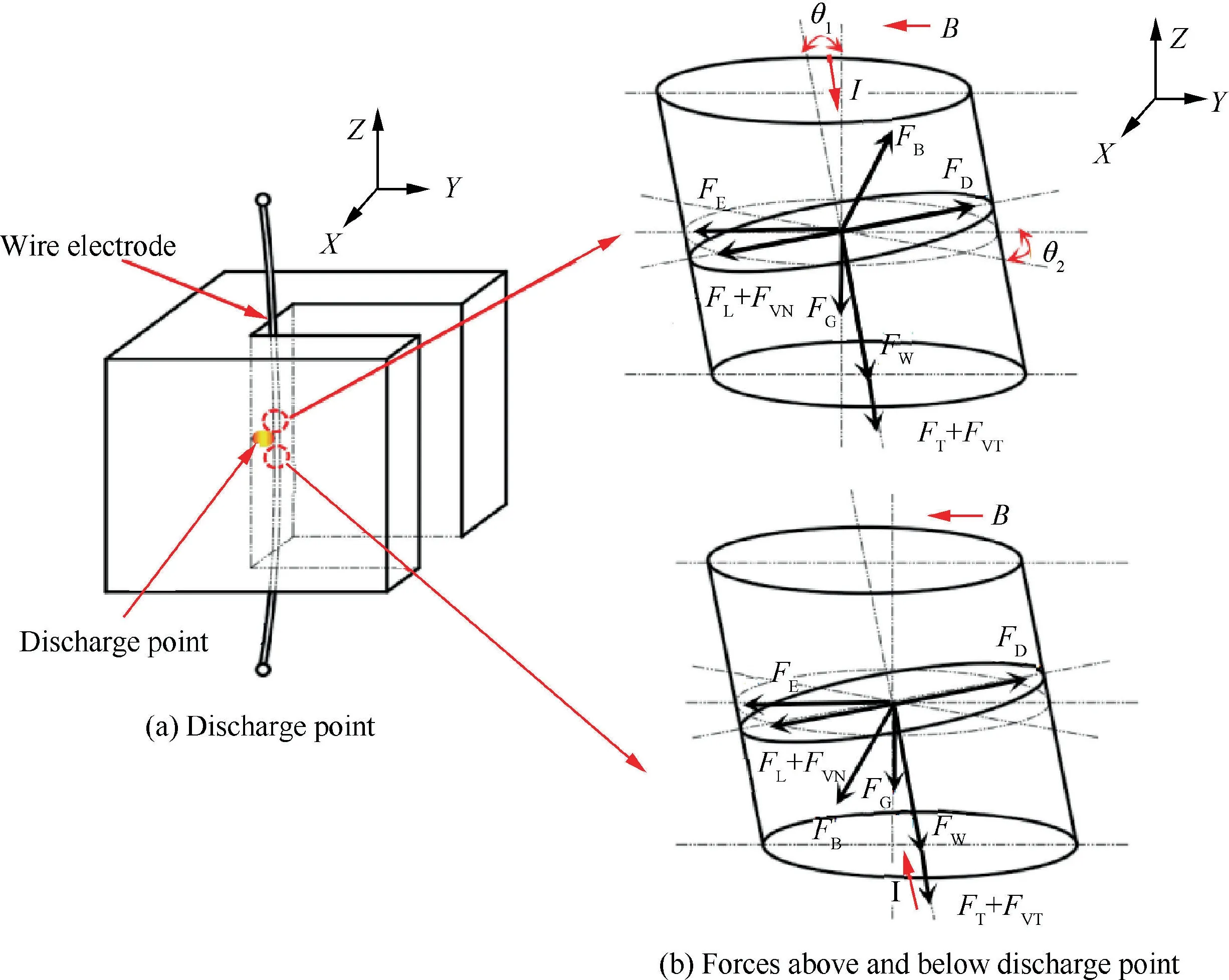
Fig.4 Force analysis diagram of wire vibration (θ1 is the wire deformation angle and θ2 is horizontal discharge force angle).

where θis the wire deformation angle and θis the horizontal discharge force angle,andis positive above the discharge point,while negative below the discharge point.can be calculated from:

whereis the magnetic field strength,is the current andis length of the wire in the transverse magnetic field.
It can be found from Eqs.(4)and(5)that the Ampere force induced by the transverse magnetic field increases the resultant force.Substituting Eqs.(4)and(5)into Eq.(3),larger value of vibration response of wire electrode() can be obtained due to larger resultant force(λτ)in the presence of transverse magnetic field,which leads to stronger forced vibration and larger vibration amplitude of the wire compared to without magnetic field.Specifically,the large resultant force leads to increasing motion of wire electrode as well as enlarging the amplitude of the wire motion.The feeding motion of the wire has an effect on the gap distance between wire and workpiece,and large amplitude of the wire vibration can narrow the gap distance so as to increase the possibility of discharge considering the same breakdown distance.Thus,larger vibration amplitude of the wire means more points on the wire have opportunity to be located in the discharge gap,which increases the discharge possibility of the above points and reduces the concentration of discharge points along the thickness direction,leading to more uniform material removal,residual stress distribution and smaller distortion.
Debris generated in the discharge process is also associated with discharge point distortion.On the one hand,more debris means more undesirable discharge gap conditions.Some debris exists in the discharge gap,while some adheres to the workpiece surface,and both situations lead to more abnormal discharges such as arc discharges,multiple discharges,short circuits and so on.On the other hand,more debris will resolidify on the workpiece surface and then produce thicker recast layers,greater gradients of residual stresses and distortion.Lorentz forces induced by a transverse magnetic field will change the movement path of charged debris into cycloid curves.The velocity and path equation can be expressed by Chen et al.:whereis the mass of a charged particle,is its charge,v,v,vand,,are initial velocity and position in the,axis directions,respectively.

For intuitively describing the effect of transverse magnetic field on charged debris motion,a trajectory simulation of the charged debris is performed.In the discharge gap,the charged debris may be in the form of ions,ionic compounds or charged particles.Niions are selected for trajectory simulation because it is the main ion component in Inconel 718 used as the experimental material.The simulation parameters are displayed in Table 1.
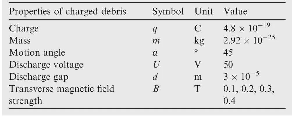
Table 1 Simulation parameters of motion of charged debris.
According to the results by Mastud et al.,the ejection velocity of debris is approximately 328.9 m/s.Based on Eq.(6),the arrival time of an ion from the workpiece to the wire electrode is 6.39×10s.The above parameters are input into Eq.(6)to calculate the trajectory of the charged debris.As for two kinds of charged debris with velocitiesand,respectively,as shown in Fig.5(a),the trajectory of particles in different transverse magnetic field strength can be expressed by Matlab simulation without considering the water flushing and particles collision as shown in Fig.5(b).
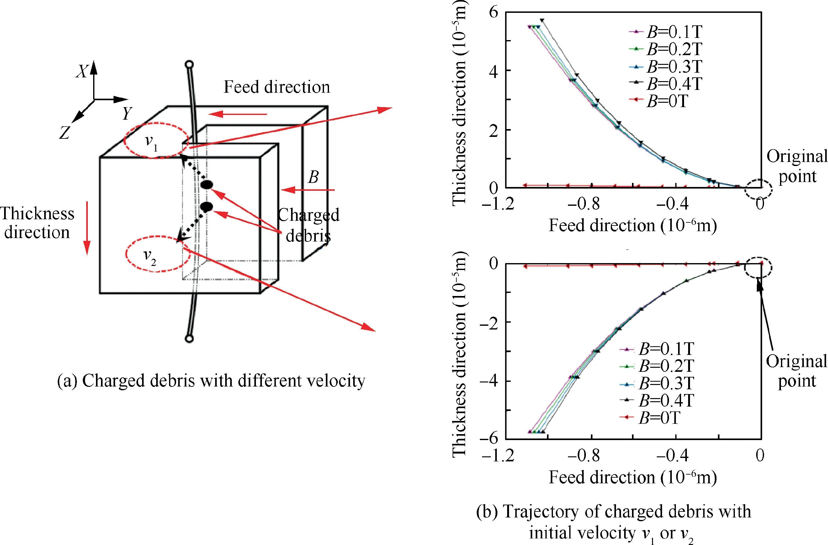
Fig.5 Trajectory of charged debris under different magnetic field strengths.
As shown in Fig.5(b),the original point of horizontal coordinates is located at the right of axis,and the horizontal coordinate value denotes the lateral distance of charged debris from workpiece surface.The vertical and horizontal coordinate values determine the position of charged debris in discharge channel after expelled out from workpiece surface.It is obviously seen from Fig.5(b) that the motion of charged debris shows a significant deflection behavior towards the thickness direction in the presence of a transverse magnetic field compared to common WEDM whether the initial velocity isor,which indicates that an assisting transverse magnetic field has a positive effect on expelling debris from the discharge gap,and then contributes to cleaner discharge conditions and more uniform discharge point distribution.
3.2.Mechanism of transverse magnetic field assistance on distortion
As analyzed in Section 3.1,a transverse magnetic field has a positive effect on the uniformity of discharge point distribution by changing and controlling the wire vibration and debris removal.A more uniform discharge point distribution contributes to more uniform heat transport and material removal,which lead to a smaller difference in the temperature fields and residual stress fields along the thickness direction of the workpiece.Thus,a transverse magnetic field has the potential to reduce the distortion in WEDM.
4.Simulation model of the distortion process
4.1.Modeling of discharge point distribution
To accurately simulate the distortion process in WEDM,the discharge point distribution along the thickness direction must be firstly obtained as the input factor for the determination of the heat source distribution.
The workpiece is equally divided into ten zones (from Zone 1 to Zone 10) as displayed in Fig.6(a) to count the number of discharge points and deduce its distribution curve in the form of a Gaussian distribution expressed by:

where zis the location in theaxis,the discharge number,and,,andare constant coefficients depending on process parameters.All discharges in each zone can be regarded as occurring simultaneously due to pulse discharge time is far smaller than the feed speed.
The distribution rule of discharge points in each divided zone should also be determined.According to the research by Hinduja et al.,the discharge points do not definitively occur at the closest location between the sample and electrode.The mathematical model of massive discharge point locations is developed based on the stochastic process nature and probability theory to characterize the occurrence of sparks in each divided zone as shown in Fig.6(b).The center coordinates(y, z) of the location of theth discharge point in Cartesian coordinates is given by Herrero et al.:
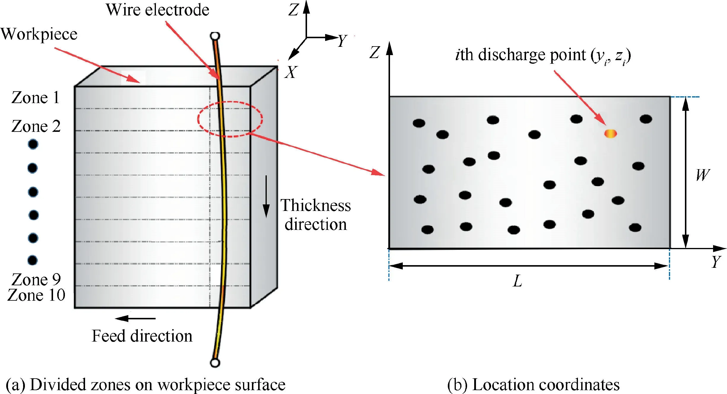
Fig.6 Modeling distribution of massive random discharges.

where mand ndesignate the length proportion coefficient randomly varied from 0 to 1,the zone length depending on the feed distance in a certain time,andthe zone width.
4.2.Distortion simulation model
A new thermo-physical model considering the discharge point distribution is established based on our previous model.The size of the model is 11 mm×0.4 mm×10 mm to match the experimental size.The mesh model is displayed in Fig.7.Inconel 718 is selected as the sample material,and its temperature dependent material properties,including specific heat,thermal conductivity,thermal expansion and Young’s modulus are all considered.The heat source model for each discharge point is based on the Gaussian distribution as expressed by Cheng et al.:
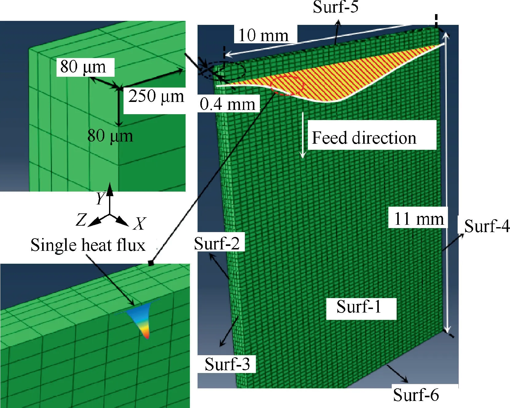
Fig.7 Three-dimensional FEM model considering discharge point distribution.

where() denotes the heat flux,the ratio of energy absorbed by the workpiece which is set as 0.3,the radius from the discharge channel center,the radius of the discharge plasma,and λthe discharge point coefficient.The number and distribution of heat sources are determined by the model of discharge point distribution as described by Eq.(7).However,thousands of discharge points occur per second in WEDM,which greatly increases the computational burden of the model.A simplification is made by also dividing the model into ten zones as shown in Fig.6.Each region is covered by one heat source also with a Gaussian distribution,while its magnitude is determined by the number of discharge points.The validity of this heat source will be verified in the following section.After heat sources are determined,the transient thermal analysis is performed to calculate the temperature field,which then serves as the input to determine the stress fields and distortion based on temperature-dependent materials properties.
The initial temperature of the model was set to room temperature(20°C),and the Surf-6 is set as fixed as shown in Fig.7.The Fourier heat conduction equation is used as the governing equation:

whereis the thermal conductivity,ρ the material density and Cthe specific heat capacity of the material.
The temperature boundary on the model surface,was set to:

whereis the heat flux outside the discharge channel of convection,is the convection coefficient,andandare the temperature in the machining process and room temperature.The boundary condition at the surface where the heat flux is applied is divided into two parts.As for the surface inside the discharge channel,the heat flux conduction is shown by Eq.(9),while for the surface outside the channel,conduction can be described by Eq.(11).
The heat convection condition applied to Surf-3 and Surf-4 considers the quenching effect of the dielectric fluid,while the heat convection coefficient () can be obtained from:

whereis the local distance depending on model size,is the thermal conductivity of the deionized water andis the Nusselt number based on flow rate.The convection coefficient() of Surf-5 is given by Hinduja et al.:

wheredesignates to variable that is defined to simplify the calculation,α designates to temperature coefficient of the electrode material,Ω the constant,the output voltage,the output voltage before the wire is heated,is the wire radius,and β the amplification of the differential signal amplifier.This convection coefficient is also closely associated with the water flushing pressure and gap condition.
A few assumptions were proposed for this thermo-physical model.
(a) Each discharge delay time is zero,and each spark has the same discharge energy and time.
(b) Heat conduction and convection are considered,while radiation is ignored in heat transfer analysis.
(c) Material is removed immediately and corroded completely once the temperature exceeds the melting point.
(d) The simulation boundary of the machined surface is a moving boundary with time variation due to the moving heat flux location.
(e) The heat flux and distribution of each heat source in each zone is determined by the distribution trend and number of discharge points,and remain unchanged with the moving of heat flux along the feed direction.
(f) The vibration of the wire is ignored.
Based on above description of model establishment,boundary condition and assumptions,the thero-physical model is established under the Complete Abaqus Environment by using Python scripting language.The calculation of distortion is performed by following two steps.Firstly,the moving heat sources is implemented on Surf-1,and then the temperature fields of workpiece are calculated.Part of materials is eliminated immediately once the temperature of materials exceeds melting point based on life and death element technique.The final residual stress fields and stain fields can be obtained in this model based on the temperature fields distribution and material properties.Through calculating the deformation difference between the top area and the bottom area of the model as expressed in Eq.(1),the distortion can be finally acquired.
4.3.Verification of the heat sources
Firstly,the validity of a single Gaussian heat source was verified by comparing the stress and strain fields to that of zone heat source consisting of multiple discharge points.A verification model is established using the above two heat sources with a size of 10 mm×0.4 mm×1 mm.The stress and strain fields are calculated as shown in Fig.8.It is obvious that the stress and strain fields obtained by the two heat sources are nearly the same with a relative error of 0.337% for the stress and 3.96%for the strain.So,a single Gaussian heat source can represent multiple discharge conditions and is reliable and suitable for simulating WEDM processes.
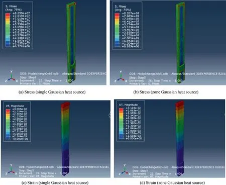
Fig.8 Stress and strain fields obtained by a single Gaussian heat source and zone Gaussian heat source.
5.Experimental procedure
5.1.Materials and equipment
Inconel 718 was specially developed and selected for aircraft applications due to its high corrosion and oxidation resistance,high strength and long creep life at elevated temperatures,particularly in manufacturing of turbine disks,diffuser cases,and compressor disks.Its mechanical properties is listed in Table 2.A high-precision CNC WEDM(model:HK-5040F)which can generate stable normal discharges through a build-in homenergic pulse generator and servo system with high precision was chosen for the experiments.Deionized water and brass wire with a diameter of 0.25 mm were utilized as dielectric fluid and electrode,respectively.Transverse magnetic field was proved as the most effective direction of assisted magnetic field for improving the machining characteristics in WEDM as described by Zhang et al.A tunable magnet device was placed around the workpiece to generate a transverse magnetic field and different magnetic field strengths.
5.2.Experimental design
A group of experiments was designed and conducted to explore the effects of machining parameters on the complex distortion behavior in transverse magnetic assisted WEDM based on the Taguchi method.Pulse on time,pulse off time,pulse current,gap voltage,wire speed and transverse magnetic field strength were selected as processing parameters due to their significant influence on deformation.The experimental levels and values of above parameters are listed in Table 3.
The distortion values of all specimens were measured by a KEYENCE VH-Z500R digital microscope at 200×magnification.The surface residual stress along the thickness direction of the distorted specimens were tested by an X-ray residual stress detector (Model:iXRD) for further analysis of the distortions.A high-speed observation system was designed to observe and record discharge point distribution along the thickness direction,which consists of an IDT-NX3.2 model high speed camera,0.1% transmittance of optical filters,heat resistant glass and computer as shown in Fig.9.The filter was used for eliminating glare interference induced by discharges,while the heat resistant glass was stuck to the sample surface to fit the actual processing conditions(normal cutting)due to the applied unilateral cutting method for observing discharge points expediently and continuously.The discharge points are recorded by the high-speed camera for 1 second under the set discharge process parameters.The surface distortion profiles were measured by the Surface Profile Tester(Model:PGI-830).The recast layer thickness of the specimen along the thickness direction was also detected by a thermal field emission scanning electron microscope (SEM) of JEOL JSM-7600F to further explore the distortion mechanism.The measured distortion values are presented in Table 4.
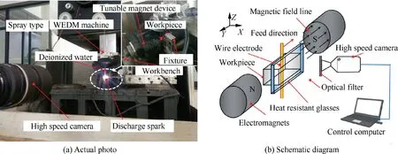
Fig.9 Observation system of discharge points during TMF-WEDM process.

Table 2 Physical properties of Inconel 718.
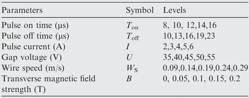
Table 3 Levels and values of machining parameters.
5.3.Verification of the model
The thermo-physical model’s validity was verified by comparing the simulation and corresponding experimental residual stress and distortion results under different process parameters.Six groups of parameter combinations were selected and the results are shown in Table 5.The average relative error is 18.38%,which is mainly attributed to the difference in the number and distribution between the actual and observed discharge points.These results indicate that the proposed thermophysical model is acceptable and useful.
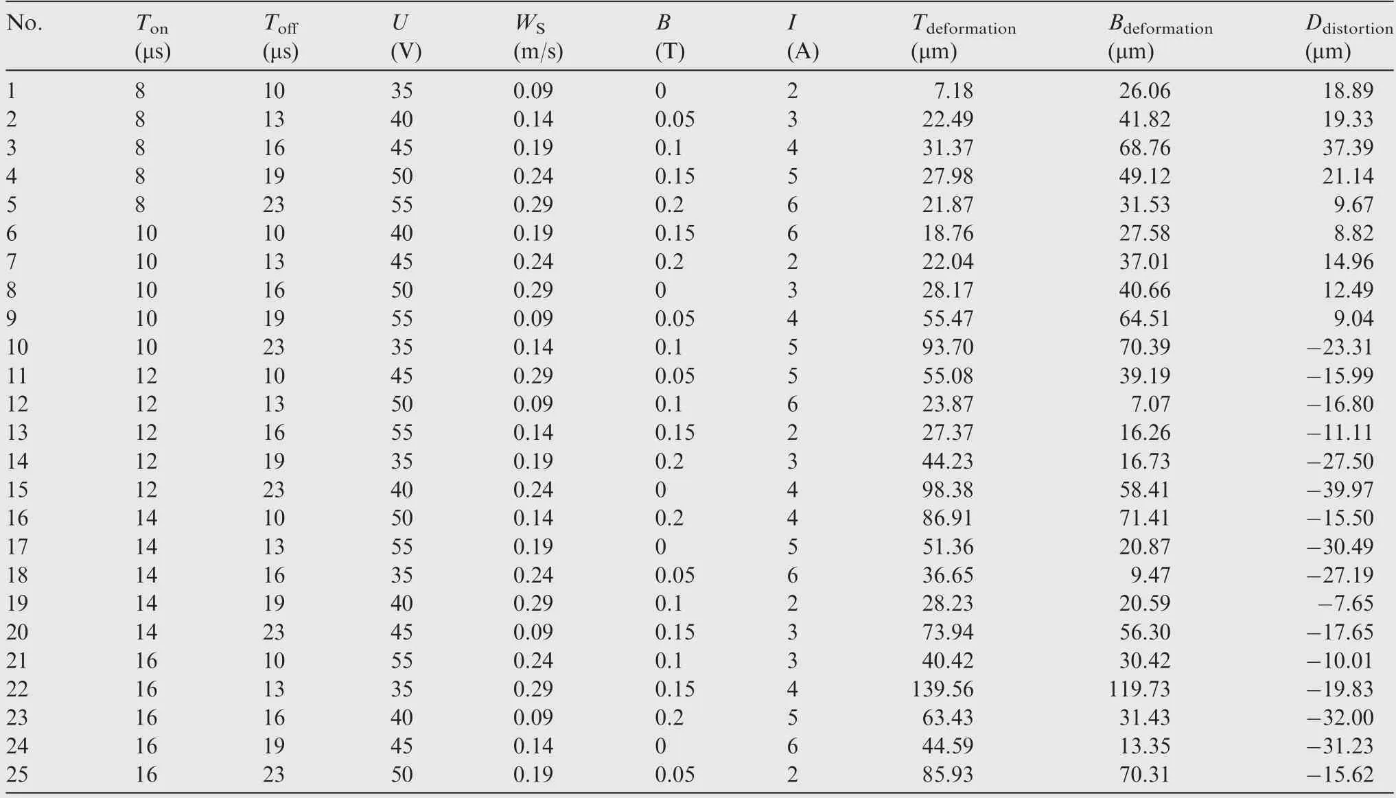
Table 4 Distortion results under transverse magnetic field assisted WEDM.
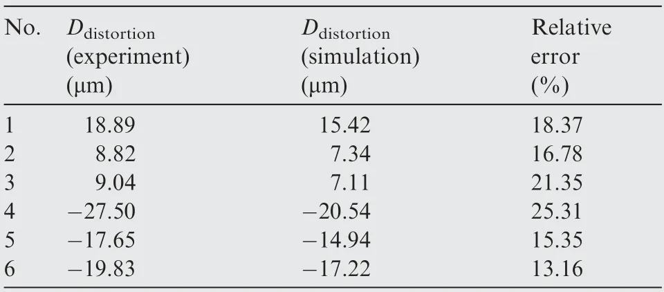
Table 5 Relative error of distortion between simulation and experimental results under transverse magnetic field assisted WEDM.
6.Results and discussions
6.1.Influence of machining parameters on distortion
Discharge parameters have a significant effect on distortion behavior in WEDM thin-wall components as shown in Fig.10.It can be seen that pulse energy (including pulse on time,pulse off time and current)play a major role in changing the distortion.There exist critical points in the impact trend of the pulse energy parameters on distortion including pulse on time(14 μs),pulse off time(19 μs) and current (4 A) as shown in Fig.10,which means that with the increase of pulse energy,distortion will increase firstly and then decrease.When the pulse energy is below a critical point,more uneven and unstable discharge conditions lead to larger distortion with the increase of pulse energy.Large pulse energy (pulse on time is larger than 14 μs and current is larger than 4 A in this paper)produces much more violent discharge sparks and material removal process,and more energy is carried away by the removed material,resulting in smaller distortion in the WEDM process.It is worth mentioning that in the range around 10 μs of,a distortion conversion region emerges(negative distortion II below 10 μs and positive distortion I beyond 10 μs) resulting from the shift in the discharge point distribution.When the pulse energy is low,the discharges concentrate at the bottom region due to wire vibration and movement,dielectric flushing and second-discharges leading to larger bottom deformation.However,when the pulse energy is large,more material is removed,more discharge points are generated and better discharge conditions exist at the top region under a more pronounced influence of the assisting magnetic field,resulting in the concentration of sparks in the top region and larger top deformation.Thus,based on above analysis of the effect of pulse discharge energy on the distortion behavior,it can be found out that when pulse discharge energy is in small range (pulse on time (8-10 μs) and current(2-4 A)),the distortion II occurs,but when pulse discharge energy is in large range (pulse on time (10-16 μs) and current(4-6 A),the distortion I appears.
From Fig.10,it can be seen that the distortion decreases with the increase of discharge voltage due to a larger discharge gap,lower discharge frequency and bubble back pressure.As for wire speed,it exhibits a complex effect on distortion by changing the wire vibration and debris removal.When wire vibration plays a dominate role,larger distortion will occur,while when debris removal is dominant,smaller distortion occurs.
6.2.Influence of transverse magnetic field on distortion behavior
The effect trend of different transverse magnetic field strengths on distortion is explored,and then the influence mechanism(discharge points distribution) is further analyzed.
The impact trend of transverse magnetic field strength on distortion is displayed in Fig.10,and it can be seen that with theincrease of transverse magnetic field strength,the distortion is obviously reduced and then increased.This is mainly attributed to the fact that on the one hand,the Ampere force induced by external magnetic field contributes to stronger forced vibration of wire electrode and more effective charged debris ejection which improve the uniformity of longitudinal distribution,and then lead uniform heat input,temperature distribution on the surface as well as relieve the residual stress gradient.However,when the transverse magnetic field strength is too large,not only the discharge channel is over contracted and redundant heat energy is transferred to local area of samples,but also violent wire vibration and terrible debris flushing are formed,which promote the formation of a molten pool with higher thermal stress,residual stress and then larger distortion.
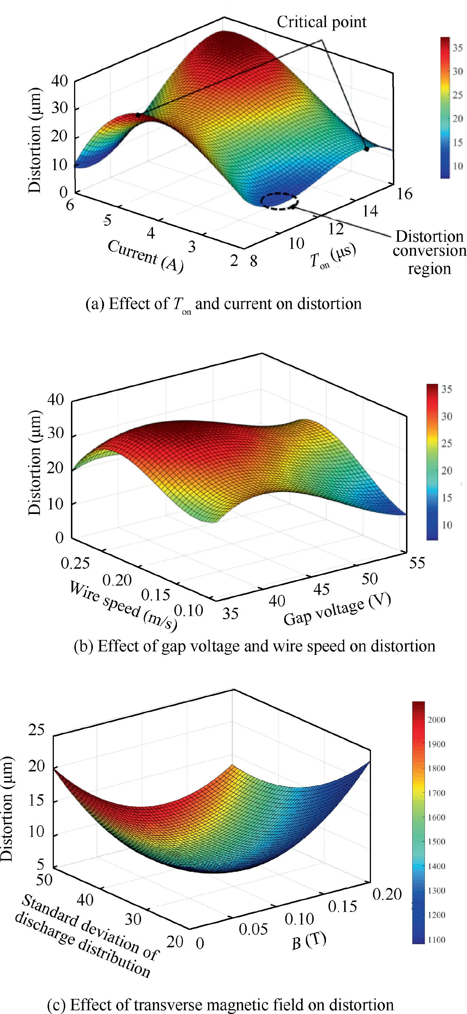
Fig.10 Effect trend of Ton,current,gap voltage,wire speed and transverse magnetic field on distortion.
To further optimize and quantify the reduction of transverse magnetic field on distortion,a group of single factor experiments with and without transverse magnetic field was conducted under the same process parameters.According to the above analysis and previous research experience,these value of process parameters and magnetic field were set as listed in Table 6.The results indicate that the distortion is reduced by 32.77% from 14.89 μm to 10.01 μm,which also verities the effectiveness of magnetic field.

Table 6 Single factor experiments with and without transverse magnetic field.
To clarify and verify the influence mechanism of transverse magnetic field on distortion,the discharge point distribution curve along the thickness direction and the effect of the transverse magnetic field on distribution uniformity and discharge quantity are investigated.The image desiccation,discharge point extraction and image thresholding algorithm are applied for visually catching the shape and size scale of the plasma as shown in Fig.11.The discharge point distribution with time changing is also acquired by image binarization and centroid methods,in which the transverse distance represents the discharge gap,and the longitudinal distance and standard deviation represent the distance and discharge point difference along the thickness direction,respectively.It is evident that the discharge point distribution shows little change with time,while more numerous and smaller discharge points gradually shift to top area of samples(small longitudinal distance)under larger discharge energy(No.22)as displayed in Fig.11(c)and(a).Moreover,Fig.12 shows that with the increase of magnetic field strength,the number of discharge points increase firstly(maximum growth by 6.38% at 0.05 T) and then decrease due to reduction of abnormal discharge points.The standard deviation of discharge point distribution becomes smaller with larger magnetic field strength indicating the improvement of longitudinal distribution uniformity of discharge point (maximum reduction by 12.32% at 0.15 T) as explained by Eqs.(3)and(6),which proved that transverse magnetic field can effectively change the discharge point distribution.
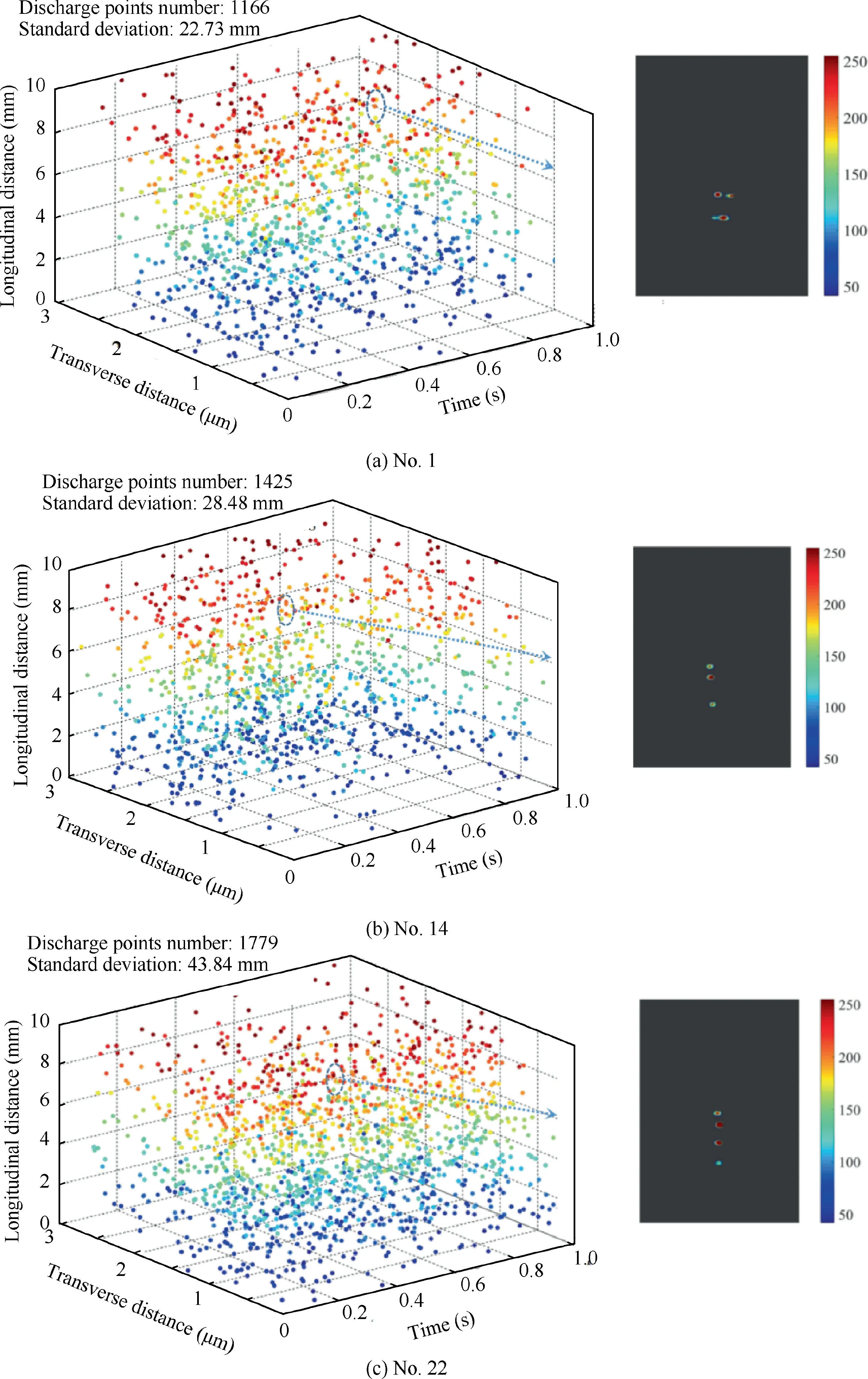
Fig.11 Two-dimensional discharge point distribution as a function of time.
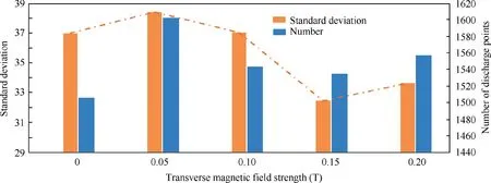
Fig.12 Variation of standard deviation of discharge points distribution and its number at different magnetic field strength.
The discharge point distribution curve is acquired by counting discharge point numbers along the thickness direction and fitting a Gaussian-like curve as shown in Fig.13.Fig.13 indicates that with the increase of pulse energy,more discharge points gradually shift to the top area and then lead to the change of distortion I and II,which further confirms ouranalysis in Section 6.1.These curves will serve as the input parameter for simulation as described in Section 4.2.
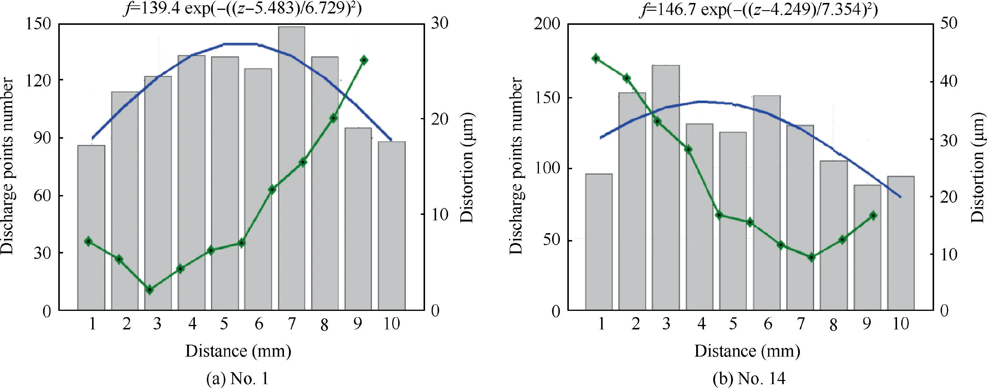
Fig.13 Fitting of Gaussian-like distribution curves.
Effect of discharge point distribution on distortion:As Section 3 stated,discharge point distribution has a directly related to the distortion behavior via the influence of transverse magnetic field.The impact trend of the standard deviation of the discharge point distribution (representing its distribution uniformity),and discharge point numbers on distortion is also displayed in Fig.10.It is clear that the more uniform discharge points distribution(with smaller standard deviation),the smaller distortion,while the number of discharge point has little effect on the distortion.
Based on the analysis of subsection 6.2.2,it can be proved that the distortion can be reduced in the presence of transverse magnetic field by changing the longitudinal distribution uniformity of discharge points.
To further investigate the non-linear phenomenon of distortion in theplane,the surface profile was measured.Due to the limitations of the measurement device,the displacement results (No.14 and No.22) were acquired at depths from 2 mm to 8 mm as shown in Fig.14.The simulated distortion profile can also be obtained based on the established simulation model (No.14 and No.22 in Table 4).From Fig.14,the distortion is non-linear along the thickness direction,and the deflections in the top and bottom areas are the largest and gradually decrease towards the middle area.The experimental distortion photos are also displayed in Fig.15,and it can be found that with the increase of pulse energy,the type of distortion changes from distortion II to distortion I as described in Section 2.Another non-linear behavior in the Y axis is generally produced by the non-linear deformation which is described by our previous researches.
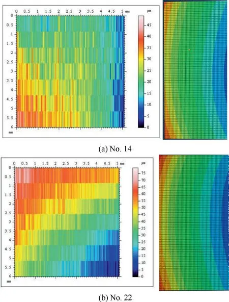
Fig.14 Experimental and simulated distortion profile along thickness direction of samples.
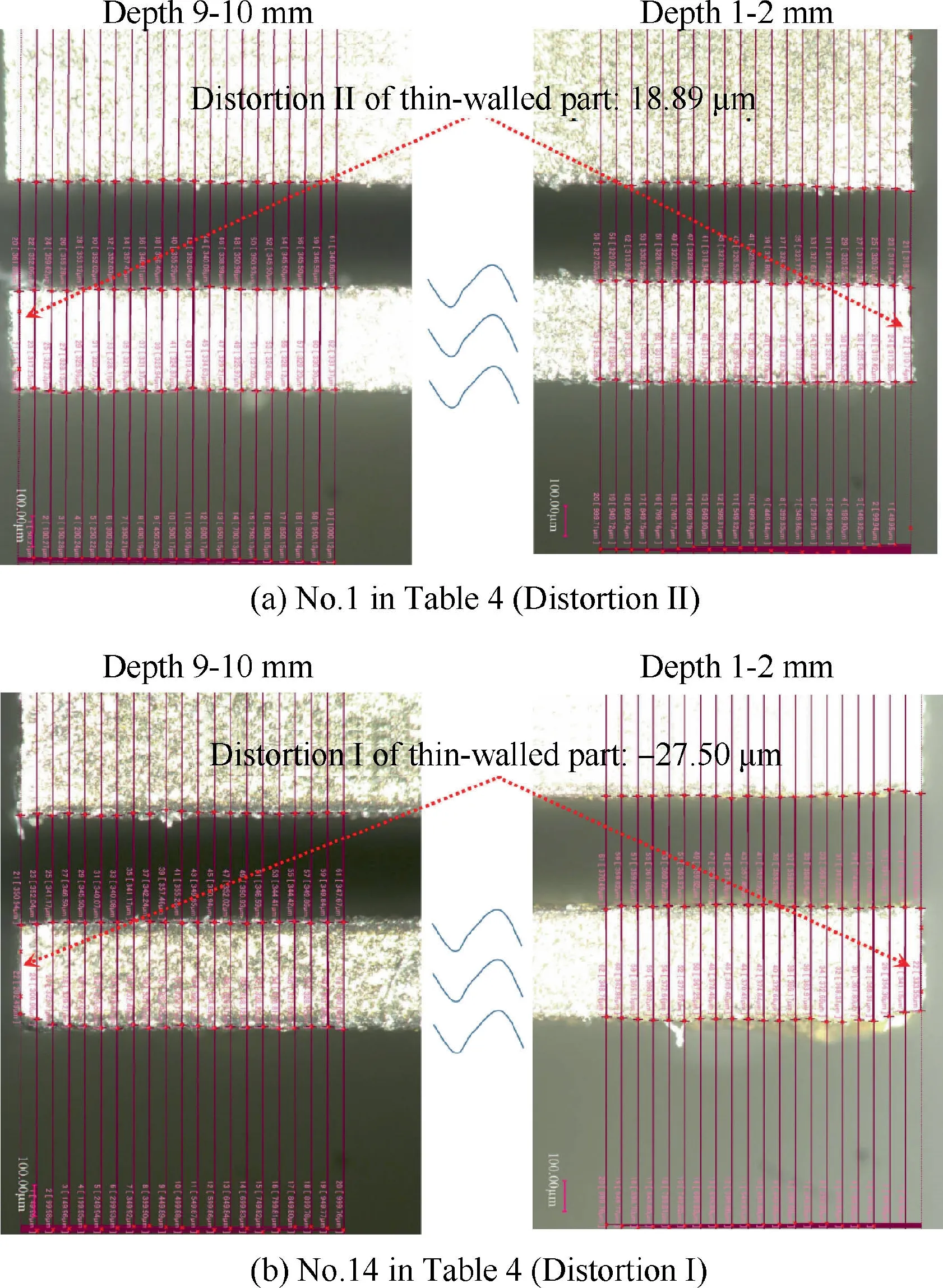
Fig.15 Experimental distortion photos along thickness direction of samples.
6.3.Relationship between residual stress distribution and distortion
In order to explore the effect of residual stress distribution on distortion along the thickness direction,eleven points were chosen from Zone1 to Zone10 (as shown in Fig.6) randomly to acquire their residual stress as shown in Fig.16.
The variation of residual stress and deflection at each point with time was simulated as shown in Fig.16(b).It can be seen that the residual stresses at points 1 and 11 are larger than those at other points,which also correspond to larger deflection.This is attributed to the fact that points 1 and 11 are located at the edge of the workpiece and are less constrained by surrounding material.Besides,the deflection at point 1 is larger than at point 11,which is because a higher heat flux(determined by a larger number of discharge points)is transferred into this area.
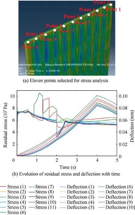
Fig.16 Simulated results of residual stress along thickness direction.
The uneven residual stress field in theaxis direction,induced by non-uniform discharge point distribution,will not only determine the gradient of the non-linear distortion in thedirection but also lead to different distortion (I and II) in the opposite direction.
6.4.Relationship between recast layer and distortion
The recast layer thickness indirectly reflects heat input in machining.A larger recast layer results from more heat energy being transferred into the workpiece and more material melted and re-solidified,leading to larger residual stresses and deformation.The recast layer results along the thickness direction and SEM photographs of two samples are shown in Fig.17(a) and(b),respectively.With the increase of longitudinal distance (defined as),the recast layer thickness initially decreases and then increases in both samples.The largest recast layer is located in the bottom area of No.1 sample(distortion II),while it is located in the top area for No.22 sample(distortion I).These results are all consistent with the trend of distortion shown before.It is worth mentioning that the value of the recast layer is small when the distance between the measured location and the surface edge is 0.5 mm,and this is due to the unsteady discharge status when the wire electrode begins to cut into the workpiece surface.To quantity the reduction of recast layer as well as distortion under different transverse magnetic field,a group of experiments was conducted under same parameters setting with Table 6.The results reveal that the recast layer can be reduced by 22.68% from 15.65 μm to 12.10 μm together with 32.77% reduction of distortion.
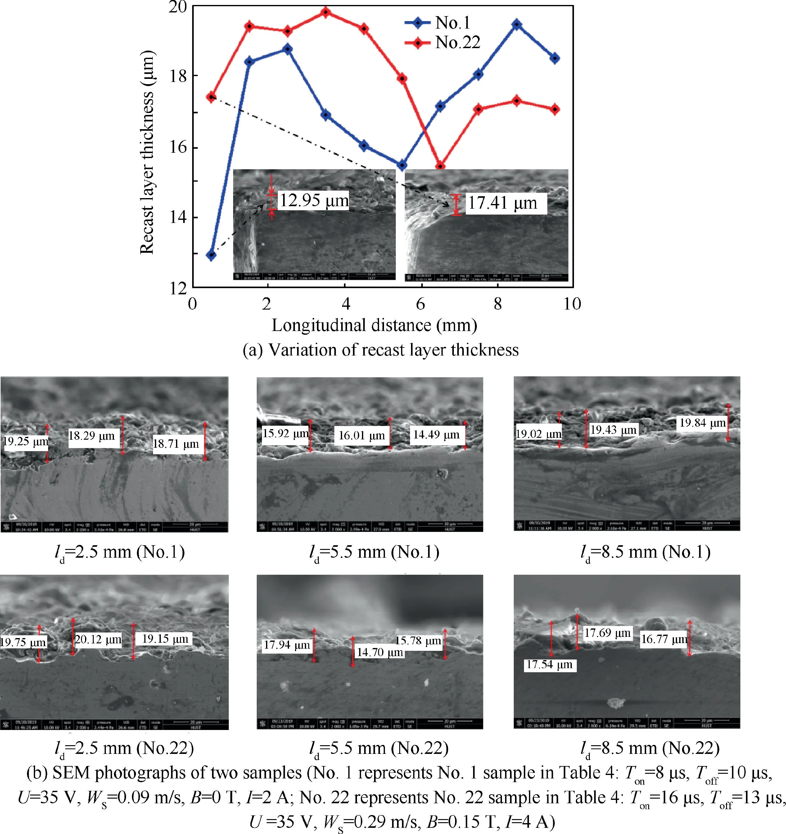
Fig.17 Recast layer along thickness direction.
7.Conclusion
(1) A new thermal distortion behavior generated in WEDM processing the aviation nickel alloy of thin-wall components was observed,and the effect trend of discharge parameters including pulse on time,pulse off time,and current on the magnitude and direction of distortion were explored.The distortion I(top deformation >bottom deformation)appears under the effect of large pulse discharge energy (pulse on time (10-16 μs) and current(4-6 A))due to larger residual stress on top area of samples compared to that of bottom area.On the contrary,the distortion II (bottom deformation >top deformation) occurs under the effect of small pulse discharge energy (pulse on time (8-10 μs) and current (2-4 A)).
(2) Transverse Magnetic field assisted technology was applied to reducing the distortion in the WEDM process of thin-walled components,and it was proved that the longitudinal distribution uniformity of discharge point continues to be improved with the increase of magnetic field strength (maximum improvement by 12.32% at magnetic field strength:0.15 T).Transverse Magnetic field contributed to the significant reductions of 32.77% in distortion and 22.68% in recast layer.
(3) Based on the theory and simulation model,the impact mechanisms of the magnetic field on distortion was revealed.The variation trends of residual stress field and recast layer were also in good agreement with the change trends of distortion I and II.The results of the established simulated model are good agreement with the experiment results,within a relative error of 18.38% in distortion.
The authors declare that they have no known competing financial interests or personal relationships that could have appeared to influence the work reported in this paper.
This research is supported by National Natural Science Foundation of China (NSFC) (Nos.51705171 and 51975228),Natural Science Foundation of Guangdong (No.2020A151501638) and the Program of China Scholarship Council (No.201806160076).
 Chinese Journal of Aeronautics2022年2期
- Chinese Journal of Aeronautics的其它文章
- Pressure-induced instability and its coupled aeroelasticity of inflated pillow
- Adjoint boundary sensitivity method to assess the effect of nonuniform boundary conditions
- Transit time difference and equal or non-equal transit time theory for airfoils with lift
- A boundary surrogate model for micro/nano grooved surface structure applied in turbulence flow control over airfoil
- Nonlinear uncertainty quantification of the impact of geometric variability on compressor performance using an adjoint method
- High precision and efficiency robotic milling of complex parts:Challenges,approaches and trends
