High precision and efficiency robotic milling of complex parts:Challenges,approaches and trends
Zerun ZHU ,Xiowei TANG ,Chen CHEN ,Fngyu PENG ,Rong YAN ,Lin ZHOU ,Zepeng LI,Jiwei WU
a School of Mechanical Science and Engineering,Huazhong University of Science and Technology,Wuhan 430074,China
b State Key Laboratory of Digital Manufacturing Equipment and Technology,Huazhong University of Science and Technology,Wuhan 430074,China
c Wuhan Digital Design and Manufacturing Innovation Centre Co.,Ltd.,Wuhan 430074,China
KEYWORDS Complex parts;Deformation;Dynamics;Robotic milling;Stiffness;Vibration control
Abstract Due to the advantages of large workspace,low cost and the integrated vision/force sensing,robotic milling has become an important way for machining of complex parts.In recent years,many scholars have studied the problems existing in the applications of robotic milling,and lots of results have been made in the dynamics,pose planning,deformation control etc.,which provides theoretical guidance for high precision and high efficiency of robotic milling.From the perspective of complex parts robotic milling,this paper focuses on machining process planning and control techniques including the analysis of the robot-workspace,robot trajectory planning,vibration monitoring and control,deformation monitoring and compensation.As well as the principles of these technologies such as robot stiffness characteristics,dynamic characteristics,chatter mechanisms,and deformation mechanisms.The methods and characteristics related to the theory and technology of robotic milling of complex parts are summarized systematically.The latest research progress and achievements in the relevant fields are reviewed.It is hoped that the challenges,strategies and development related to robotic milling could be clarified through the carding work in this paper,so as to promote the application of related theories and technologies in high efficiency and precision intelligent milling with robot for complex parts.
1.Introduction
1.1.Background
Robotic milling is an important embodiment of intelligent manufacturing.With the development of industrial robots,vision,force sensing and machine learning technologies,robotic milling has gradually occupied a certain industry field and shown a strong momentum of development.Intelligent robot machining system,which using the industrial robot as the actuator,multi-source sensors (such as vision,force and vibration) as the perception system,machine learning and intelligent cloud platform as the decision system,can complete anthropomorphic manufacturing tasks according to incomplete,inaccurate information on the working condition without certainty,prior knowledge and prediction model.In addition,the intelligent robot machining system can combine the monitoring data with the theoretical model to achieve higher accuracy and efficiency in manufacturing tasks.
Various manufacturing powers and regions in the world have put forward relevant supporting plans for intelligent robot machining technology.For example,European Union proposed the COMET Project Approach to improve the precision of machining robot,Europe proposed the Cooperation Program‘‘HEPHESTOS”for the purpose of using commercial robot to complete the difficult-to-machine materials processing.National Science Foundation of USA proposed the National Robotics Initiative (NRI 2.0) which focus on collaborative robots.The National Natural Science Foundation of China proposed a major research program‘‘Research on basic theory and key technology of communion robot”,which included the research on man-machine collaboration of intelligent manufacturing.In order to support the better application of robot in the field of intelligent manufacturing,many academic research institutions and scholars has carried out the researches of the theory on the specific scientific problems of the robot processing.Such as Fraunhofer Institute,University of Sheffield AMRC,University of British Columbia(UBC),Tsinghua University (THU),Beihang University(BUAA),Shanghai Jiao Tong University (SJTU),Huazhong University of Science and Technology(HUST),etc.Intelligent robot processing has been applied in the following two fields and remarkable achievements have been made.
These parts are characterized by large size and complex structure,and are generally processed by large five-axis CNC machine tools,occupying a large amount of factory space and high operating cost.Robotic milling is flexible and easy to expand,which can realize multi-robot processing and multi-device cooperation,and facilitate the construction and formation of an integrated intelligent system of measurement,processing and monitoring.It not only meets the processing requirements of large complex surface structure parts,but also achieves the purpose of reducing cost and improving processing efficiency.As shown in Fig.1(a),Fraunhofer IFAM developed the mobile multi-robots cooperative machining system for aircraft cabin processing.Fig.1(b)-(c),HUST-Wuxi Research Institute developed the Multi-robot grinding system for the large wind power generator blade,and constructed the robotic milling system for large marine propeller.Fig.1(d),SJTU developed a robotic milling system for edge cutting of aircraft skin.
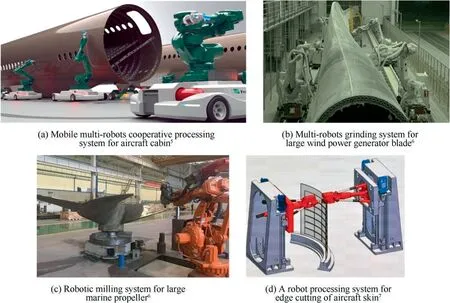
Fig.1 Robot machining of large complex curved surface structure.
The aerospace industry,as well as the future customized manufacturing,puts forward more and more demands for multivariety and small-batch parts.This kind of parts has the characteristics of uneven machining allowance distribution,high machining surface quality requirements,some parts cannot be processed by machine tools,but need the help of senior workers’superb skills.Robotic milling can integrate advanced machine vision,force perception and machine learning technologies to build a flexible intelligent robot machining system,realize autonomous measurement,autonomous decision making,autonomous execution and autonomous supervision,fully learn and draw lessons from people’s processing experience,and overcome the manufacturing difficulties of relevant parts.As shown in Fig.2(a),Fraunhofer IFAM developed the flexible robot machining system with vision measurement and robotic milling for the Airbus composite wing plates processing.Fig.2(b),University of Sheffield AMRC used KUKA Titan serial arm robot to develop a flexible robotic tooling for the aerospace and automotive companies.Fig.2(c),HUST developed the intelligent robotic milling system with binocular vision measurement,force sensing measurement and robotic milling for complex aerospace parts processing.Fig.3.
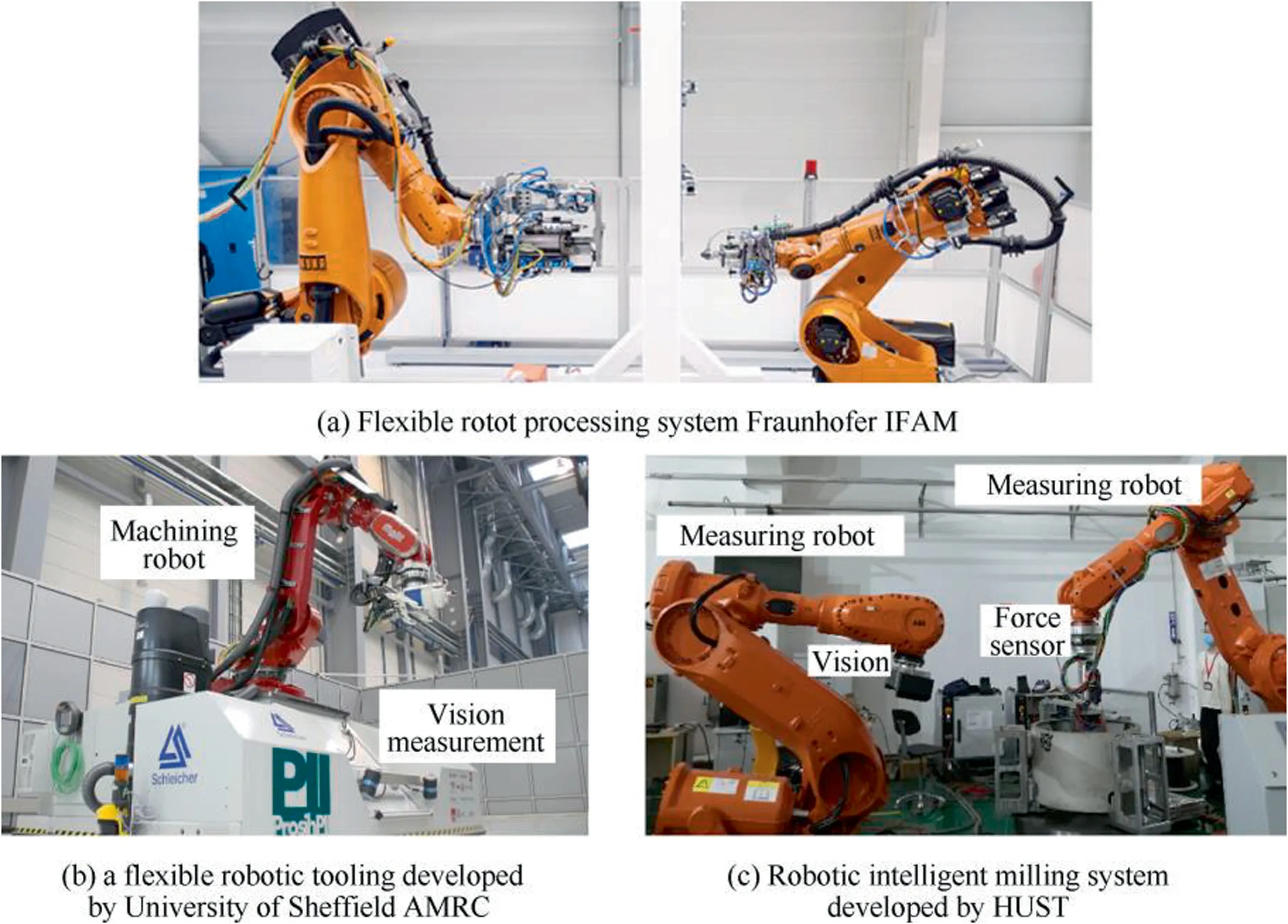
Fig.2 Flexible processing system with integrated robot measurement and processing.
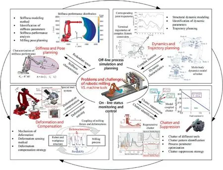
Fig.3 Problems and challenges of high precision robotic milling of complex parts.20-24
1.2.Research perspective
The development of robotic milling is not to replace CNC machine tools,but another new processing mode with its own adaptive processing conditions.From the perspective of current processing applications,the main emphasis of robotic milling applications is the rapid reconfigurable processing technology,which can quickly meet personalized processing requirements and deal with uncertain processing tasks.In this aspect,the robotic milling has achieved a certain remarkable effect and has a great potential for further development.At the same time,compared with CNC machine tools,the low stiffness,posture dependent dynamic characteristics and various configuration changes of robots will become a major challenge in processing applications (especially milling),resulting in low processing efficiency,poor processing accuracy and poor processing consistency.In order to further improve the stability and accuracy of robotic milling,and improve its intelligence level to adapt to more application conditions,the research on the theory and technology of robotic milling has become a research hotspot,and fruitful research results have been obtained.According to the previous robotic processing review articles shown in Table 1.,the current research on robotic processing is mainly focused on:robot component optimization design,precision calibration,robot stiffness and dynamic characteristics,multi-robot collaborative control strategy,trajectory planning and programming,milling vibration characteristics and reduction methods,machining deviation caused by milling forces,on-line monitoring and control of machining status,etc.
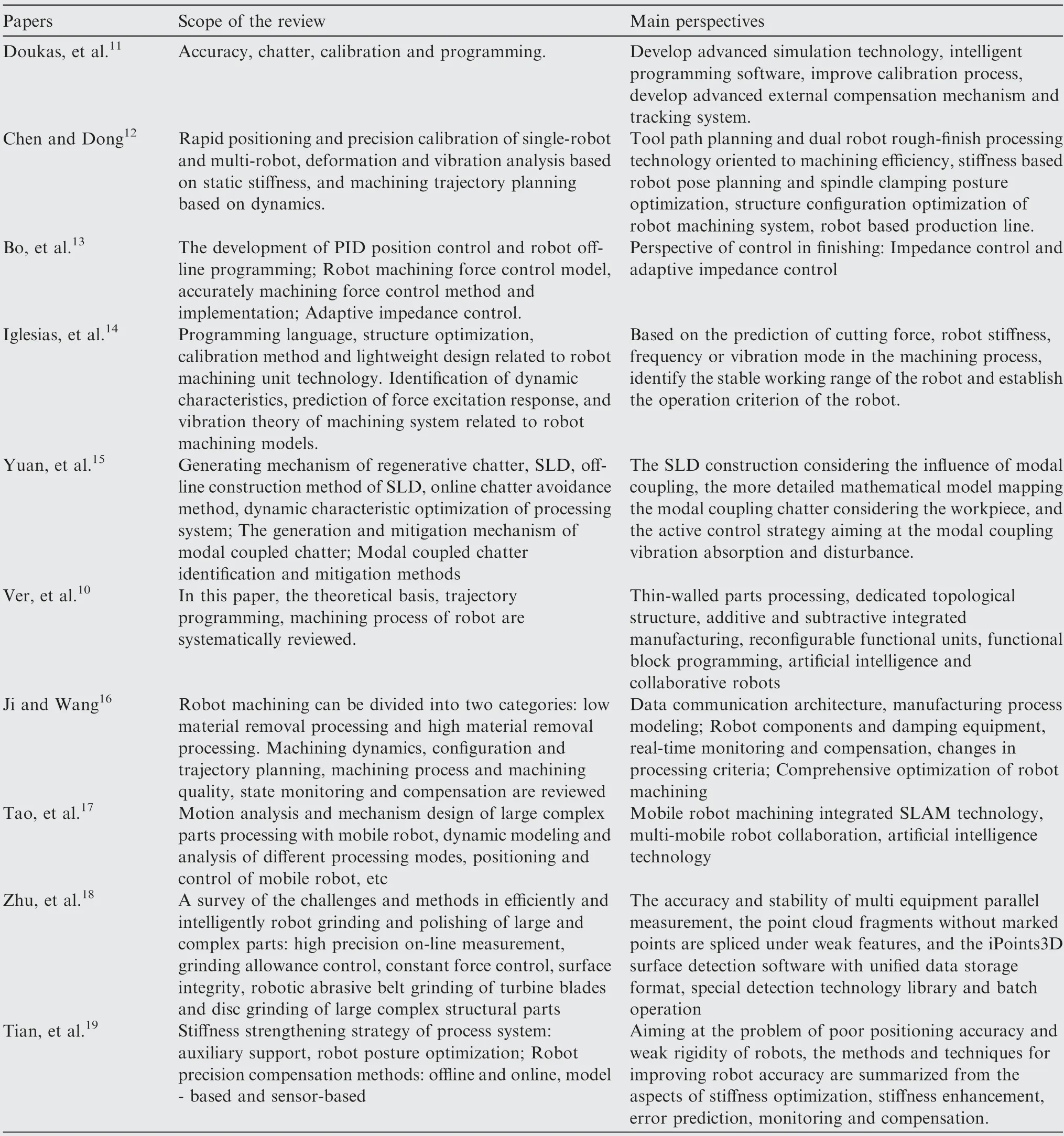
Table 1 A comparison of the review papers on robot machining.
Through the analysis of robotic milling characteristics of large complex parts and small batches of various parts,the problems to be solved under different working conditions are as follows.As shown in Fig.1,For the multi-robot cooperative processing of large complex parts,the main problem to be solved is the uneven dynamic response caused by the collaborative control of multi-robots and the dynamic characteristics of pose dependence in large workspace,so it is necessary to focus on the research of workspace planning,processing path planning and vibration suppression technology.As shown in Fig.2,for intelligent robotic milling of multi-variety and small-batch parts,the main problems to be solved include intelligent topology design of robot,analysis of stiffness of different configurations and deformation errors,analysis of machining stability of tool and workpiece,multi-source sensor monitoring and visual measurement,etc.The research focuses on structural stiffness characteristics,dynamic characteristics,processing state monitoring and intelligent compensation,etc.Based on the above analysis,this paper concludes that there are mainly four aspects of research emphasis related to robotic milling:(1) analysis of stiffness distribution related to posture in robot workspace;(2) Non-uniform distribution analysis of dynamic characteristics with pose dependence and machining trajectory planning;(3) Vibration characteristic analysis and chatter suppression of robotic milling;(4) Dynamic deformation response prediction and machining error compensation.
This paper analyzes the challenges to solve these problems that need to be solved in robot machining,summarizes the present situation of robotic milling research and the problems that still need to be solved,and gives the future develop trends of robotic milling in theoretical research and engineering application.The structure of the paper is as follows:The challenges faced by robotic milling are analyzed in Section 2.The theoretical and technical researches related to the robotic milling about stiffness,dynamic characteristics,vibration control and deformation compensation are reviewed and summarized in Section 3.The robot intelligent development trend of high efficiency and precision milling is discussed in Section 4.Some conclusions are given and the future research is prospected in Section 5.
2.Challenges of robotic milling
In this section,according to technical requirements at different process stages of robotic milling,the problems and challenges related to high precision milling of robot are analyzed and discussed,as shown in Fig.3.For the offline process simulation and planning stage,the related requirements are the robot pose planning and the trajectory planning,the inherent characteristics are the robot stiffness and dynamic respectively.For the online status monitoring and control stage,the associated requirements are the vibration control and deformation compensation,the internal mechanisms are the chatter types and the deformation modes respectively.
2.1.Off-line process simulation and planning
Due to the serial structure and redundant axis,the Cartesian stiffness of robotic milling system is significantly affected by position and posture.The Cartesian stiffness of the robot is an important factor affecting the machining accuracy,and the stiffness difference under different position and posture can be very large.However,the evaluation of machining accuracy by using the end stiffness index directly cannot fully reflect the deformation situation,which need to consider the direction and value of cutting force during the processing.Thus,the stiffness characteristics depend on the position and posture of robotic milling systems should be studied further,and the robot stiffness index,deformation index and flexibility index which are used to evaluate the robot stiffness performance.In addition,the comprehensive stiffness of robot end with considering the structural stiffness and cutting force inmilling should be studied further.Based on the above stiffness index,the robot pose planning is realized under the optimal control of static stiffness deformation error.
Chatter and forced vibration are the unstable processing phenomena in robotic milling,and both related to the dynamic characteristics of the robotic milling system.Due to the serial structure and redundant axis,the dynamic characteristics of the milling robot is effected by its position and pose observably.Thus the prediction of chatter and forced vibration of the milling in robot workspace will be more complex.In order to plan the robotic milling trajectory and cutting parameters reasonably,it is necessary to accurately predict the frequency response function related to the position and pose of robot.The structure of the robot joint is complexand the dynamic have nonlinear characteristics related to joint angle,and the contact stiffness and damping of joint is difficult to be identified.Besides,the links structure of the robot is complex and its dynamic characteristics cannot be ignored,and also be influenced by the additional mass such as cables,pipeline packages,and the mounted measuring sensors.From the above,it is extremely difficult to establish the prediction model accurately only by using the mechanical theory,such as Timoshenko beam,Euler beam or finite element method,etc.,therefore,more research methods should be investigated for the accurate frequency response prediction of robotic milling system with different position and pose.
2.2.On-line status monitoring and control
Chatter is a common unstable state in milling,and many research has been carried out on the chatter in milling of CNC machine tool,the chatter in the robotic milling is different from that in CNC machine tool due to the serial structure and redundant axis of robot.The mode frequency(10 Hz)of the robot structure is significantly lower than that of the cutter mode frequency (greater than 200 Hz),however their dynamic stiffness is of the same order of magnitude.Thus,beside the regenerative chatter,the modal coupled chatter will appear in the robotic milling Cordes et al.Moreover,when two kinds of the chatter occur at the same time,the dynamic cutting thickness generated by modal coupled chatter will also affect the formation of dynamic cutting thickness of regenerative chatter,which will influence the mechanism of regenerative chatter.In addition,compared with CNC machine tools,the redundancy angle also needs to be optimized in the multi-axis machining parameters optimization.From the above,first of all,the mechanism of modal coupled chatter in robotic milling should be studied.Secondly,the influence law of the interaction between the robot structure mode and the cutter mode on the chatter mechanism under different spindle speeds should be deeply explored,and the milling parameter planning under the different combination of cutter axis vector and redundant angle should be studied.
In the process of milling,the dynamic stiffness of the robot is relatively weak,so the dynamic deformation cannot be ignored besides the static deformation.When the spindle speed is high and the material removal rate and the peak value of milling force do not change much,the deviation value of the robot end in the milling tends to be constant,which is the static deformation.If the spindle speed is low,when the frequency of the milling force excitation is close to the robot’s natural frequency (for example,below 100 Hz),the tool deformation of the robot will vary with the frequency of the milling force,which is the dynamic deformation.If there is a sudden change in cutting direction or cutting state during the milling process,resulting in a sudden change in milling force,the robot end tool deformation presents a dynamic change similar to the step response.The dynamic deformation and static deformation are of the same magnitude in the robot machining,so there is a dynamic coupling between milling force and deformation.Therefore,it is a challenge to study the deformation error under coupling of dynamic deformation and cutting force in robotic milling.
3.Theory and method of robotic milling for complex parts
3.1.Robot stiffness characteristics and working space
The modeling methods of robot stiffness mainly include finite element approach (FEA),matrix structure approach (MSA)and virtual joint approach (VJA).The advantages and disadvantages of relevant methods are shown in Table 2.For the robotic milling of complex features and curved surface parts,the robot pose changes greatly,FEA and MSA cannot be directly used to analyze the stiffness characteristics of the robot in the workspace,and cannot reflect the impact of milling force and robot pose changes on the robot stiffness.Although VJM is convenient for the parametric analysis of robot stiffness,it has the problem of prediction accuracy due to many assumptions.In particular,the initial model only considers the flexibility of joint and does not consider the influence of external load and the flexibility of link.

Table 2 Modeling methods and application of robot stiffness.
On the basis of VJA,in order to further improve the stiffness prediction accuracy of the robot under different working conditions,many progresses have been made as follows:
Assuming that the robot link is a rigid component,the flexibility of virtual joint related to drive and reducer is only considered.The VJAis proposed to model and analyze the serial robot stiffness,and the stiffness parameters are identified by applying external forces/torques and measuring the end deviation of the robot.This method is suitable for analyzing the changing law of the end stiffness of different robot configurations and has a good effect under the static state and constant external force of the robot.Workspace analysis and milling pose optimization can be carried out in the process of robotic milling of complex parts.
The conservative stiffness mapping method,which is also described as the compensation stiffness model,was proposed to analyze the stiffness change mechanism under the combined action of robot motion and external forces through the energy balance theory.The compensation stiffness model is related toexternal load and robot posture,and no additional stiffness parameters are added.The identification method of stiffness parameters is similar to the virtual joint stiffness.This method can be used to analyze the influence of milling force and robot configuration change on the end stiffness of the robot.The larger the load and the greater the variation of robot configuration,the larger the compensation stiffness.
Considering the flexibility of robot link,Hoevenaars et al.proposed a Jacobion-based stiffness analysis method based on screw theory,which decomposed the robot structure into drive joints,passive joints,zero stiffness joints and external constraints,and analyzed the influence of relevant factors on the stiffness of the robot.Klimchik et al.extracted the stiffness data through the CAD model of a single link by FEA.This method could obtain the stiffness matrix considering the complex link structure,the coupling of rotation/translation deformation,robot joints and other factors.This method integrates the FEA-based stiffness model parameter identification technology into the VJM modeling method,as the flexibility of robot link is taken into account,the stiffness model with higher precision can be obtained.
In order to improve the stiffness prediction accuracy of the robot,other nonlinear factors have been taken into consideration,such as the nonlinear stiffness model with geometric errors of the kinematic chain,the improved VJA model with the influence of structural gravity,and the stiffness model with the influence of gravity balance device as shown in Fig.4.For a more accurate stiffness model,considering the influence of gravity compensator of heavy-duty robot,Klimchik et al.proposed the identification method of geometric and elastic parameters,which was verified on Kuka KR-270 robot.Considering the influence of gravity balance device,Yang et al.proposed a stiffness identification method based on servo current and relevant position deviation.Compared with the traditional method based on robot end load and deviation monitoring,it can obtain more accurate joint stiffness,and it was verified on HH-150 industrial robot.Nguyen Vu and Kuoproposed a modeling method of stiffness including spring articulated compensating device under the influence of gravity,elastic force and external load,and defined Compliant Uniformity Index through torque and positioning error,to evaluate the flexibility of structure and the consistency of positioning error of robot.Considering the influence of kinematic chain error,structure weight and external auxiliary device,the accuracy of stiffness prediction for heavy and heavy duty robots under specific working conditions is solved,and the desired effect is achieved.
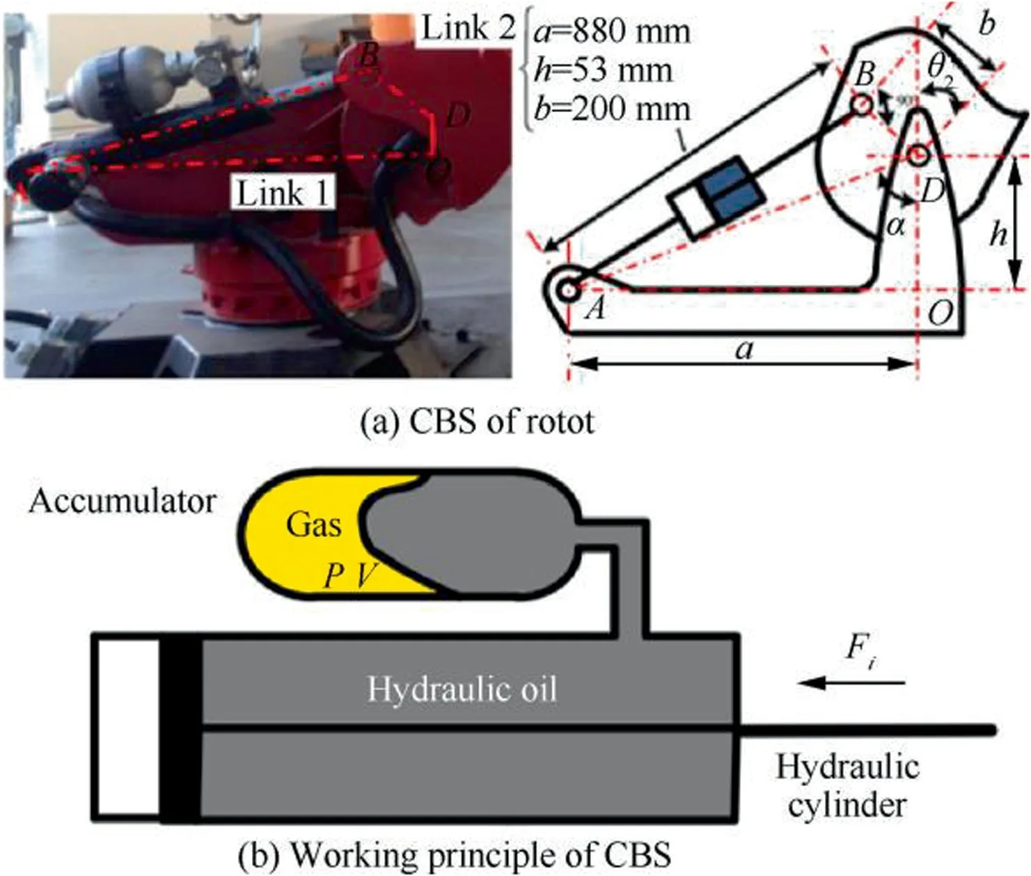
Fig.4 Mechanics of the HH-150 robot.62
In addition,combining the data-driven method is the development trend of intelligent robotic milling.In terms of stiffness parameter identification:Klimchik et al.combined algebraic model derivation and data method to realize stiffness identification considering industrial environmental noise.Considering the modeling difficulty of non-geometric factors such as deformation of link and joint stiffness,Nguyen et al.uses the method of artificial neural network to identify and compensate the un-modeled errors related to stiffness characteristics.
From the perspective of workspace analysis and robot configuration optimization application,the stiffness index of different robot working positions can reflect its stiffness state,deformation error,etc.,but compared with the stiffness prediction and deformation simulation,the calculation amount can be greatly reduced.The research on the stiffness index of robot has also changed from considering the virtual joint stiffness only,to considering the external load,and then to considering the gravity compensation and flexible parts,etc.The relevant research progress is shown in the Table 3.
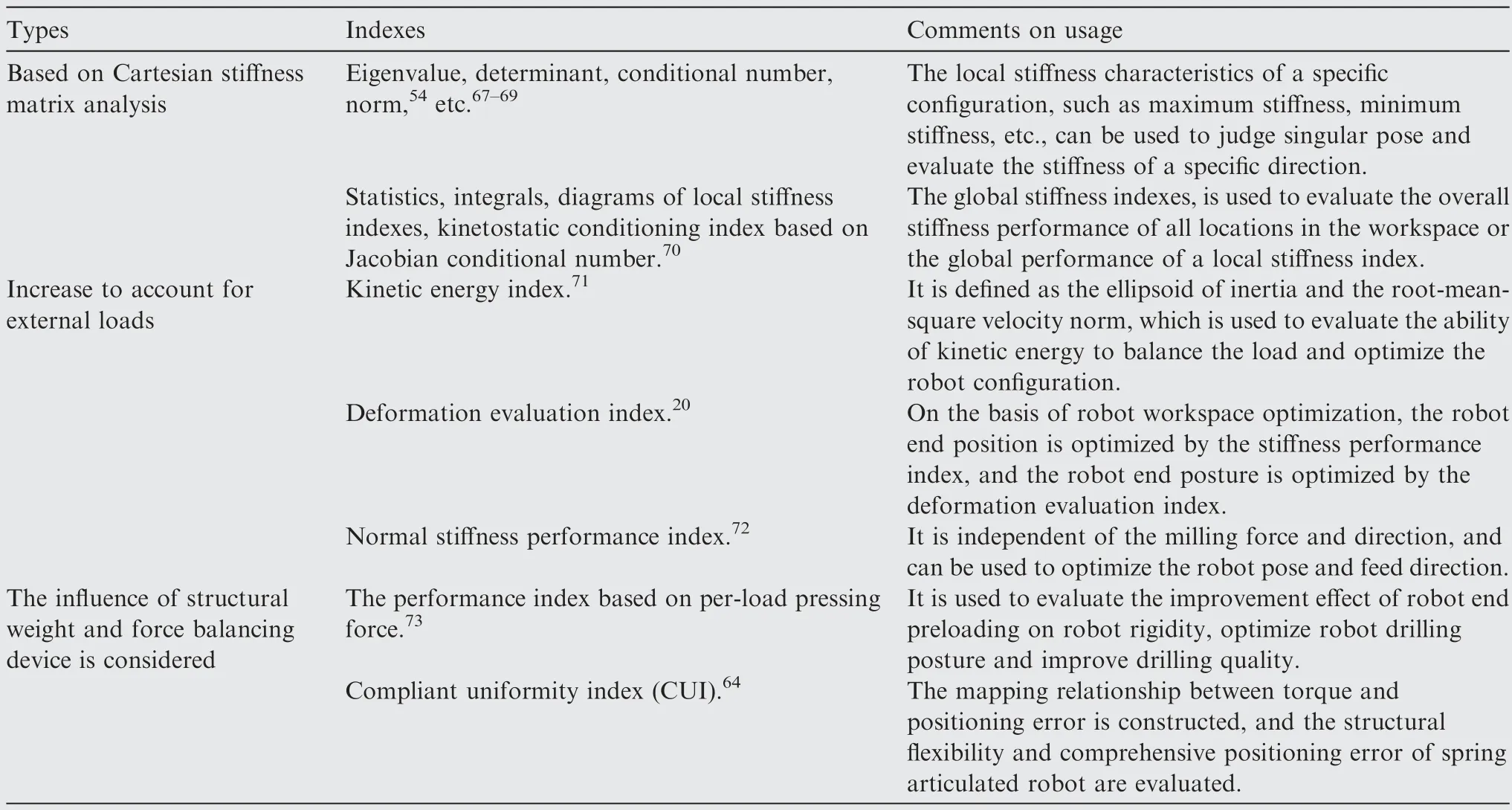
Table 3 Indexes related to robot machining stiffness.
Cartesian stiffness matrix is used to analyze the static stiffness of the robot,such as eigenvalue,determinant,condition number,normand other indexes related to specific configuration of the robot.It is used to analyze the local stiffness characteristics of specific robot pose,such as maximum stiffness and minimum stiffness,etc.It can be used to judge singular pose and evaluate the stiffness value in a specific direction.As well as the global stiffness indexes related to the workspace,such as the statistics,integration and diagram of local stiffness index,and the kinematics conditional index based on Jacobian conditional number,these are used to evaluate the comprehensive stiffness performance of all positions in the workspace or the global performance of a local stiffness index.In view of the low efficiency of manual weighting,Huo and Baronproposed an adaptive method for joint limit and singularity avoidance for redundant DOF robot posture planning with multiple constraints.
Robot load,such as milling force,is an important factor affecting the deformation and accuracy of Robot machining.In recent years,scholars have studied the milling accuracy of robots with different attitudes through load related indexes.Considering the characteristics of robot joint drive and motion:Zargarbashi et al.proposes the ratio index of robot transmission,quantifies the effectiveness of joint driving force to maintain robot posture,and is used to series redundant axis and trajectory planning of industrial robots to avoid saturation of robot speed and torque.Nabavi et al.defined the kinetic energy index as the inertia ellipsoid and the RMS velocity norm,which is used to evaluate the ability of kinetic energy to balance load and optimize the robot configuration.Zanchettin et al.adopt torque effectiveness index to carry out robot configuration planning on the upper level ofkinematics control.Considering the effect of the end load,Lin et al.optimized the robot’s end position through the stiffness performance index on the basis of the optimization of the robot workspace,and optimizes the robot’s end posture through the deformation evaluation index,as shown in Fig.5,so as to achieve the optimal comprehensive machining performance.Chen et al.proposed the performance index of normal stiffness,which is related to the force direction of the robot end and is used to optimize the robot posture and milling feed direction to improve the milling accuracy of the robot for specific parts.Liao et al.proposed a region-based tool path generation method for robotic milling with stiffness index CCN as shown in Fig.6,the magnitude of the CCN is plotted with the color depth.For a robot pose,the deeper is the blue,the better is the robot stiffness.Based on the relationship between the deviation of tool translation at the end of the robot and the force,the stiffness characteristic index of the robot was proposed,Cordes and Hintzecarried out the experiment with ABB IRB 6660 and reached the following conclusions:(1) The tangential deviation along the radius of joint 1 is the largest,and the error reaches 1-2 m/N.The method to reduce the error is to place the workpiece as close to the robot’s base coordinate system as possible,to avoid the normal force in the tangent direction of joint 1;(2) When the cutting force is low,hysteresis is the main cause of the error,which determines the bidirectional repeatability of the robot.Xiong et al.considered the multiple pose solutions brought by redundant axes of robots,and put forward the stiffness-based pose optimization method,integrated the method into CAD or CAM software,and realized the conversion of NC programming into robot programming.
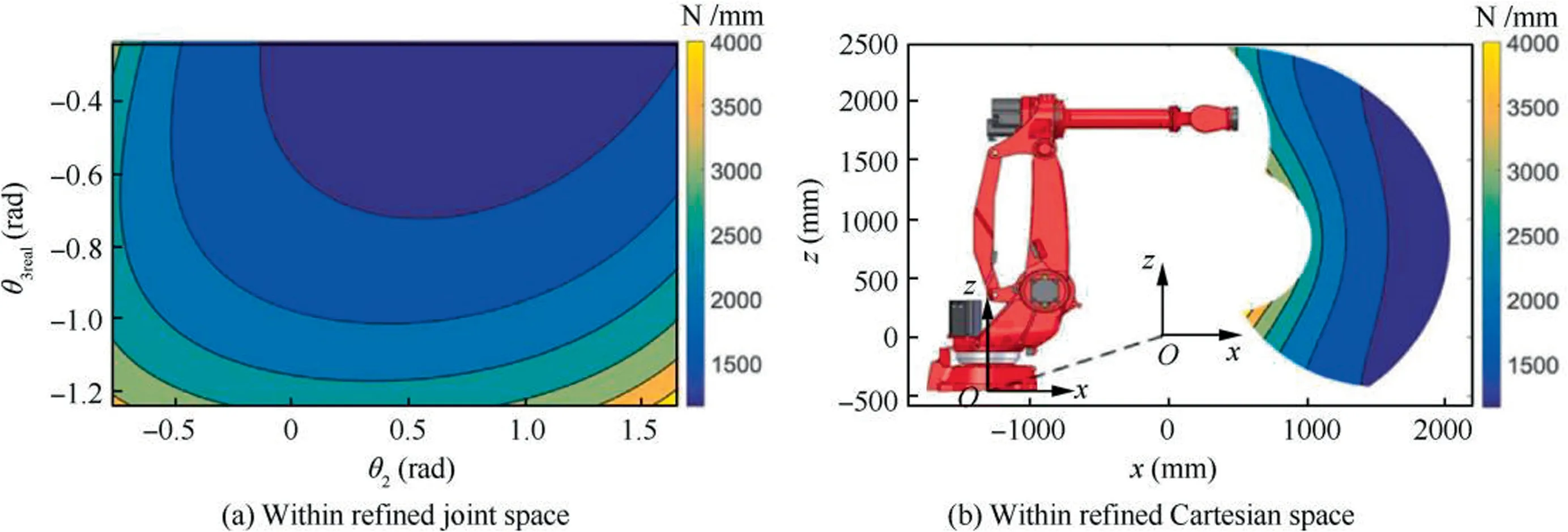
Fig.5 Stiffness performance maps 20.
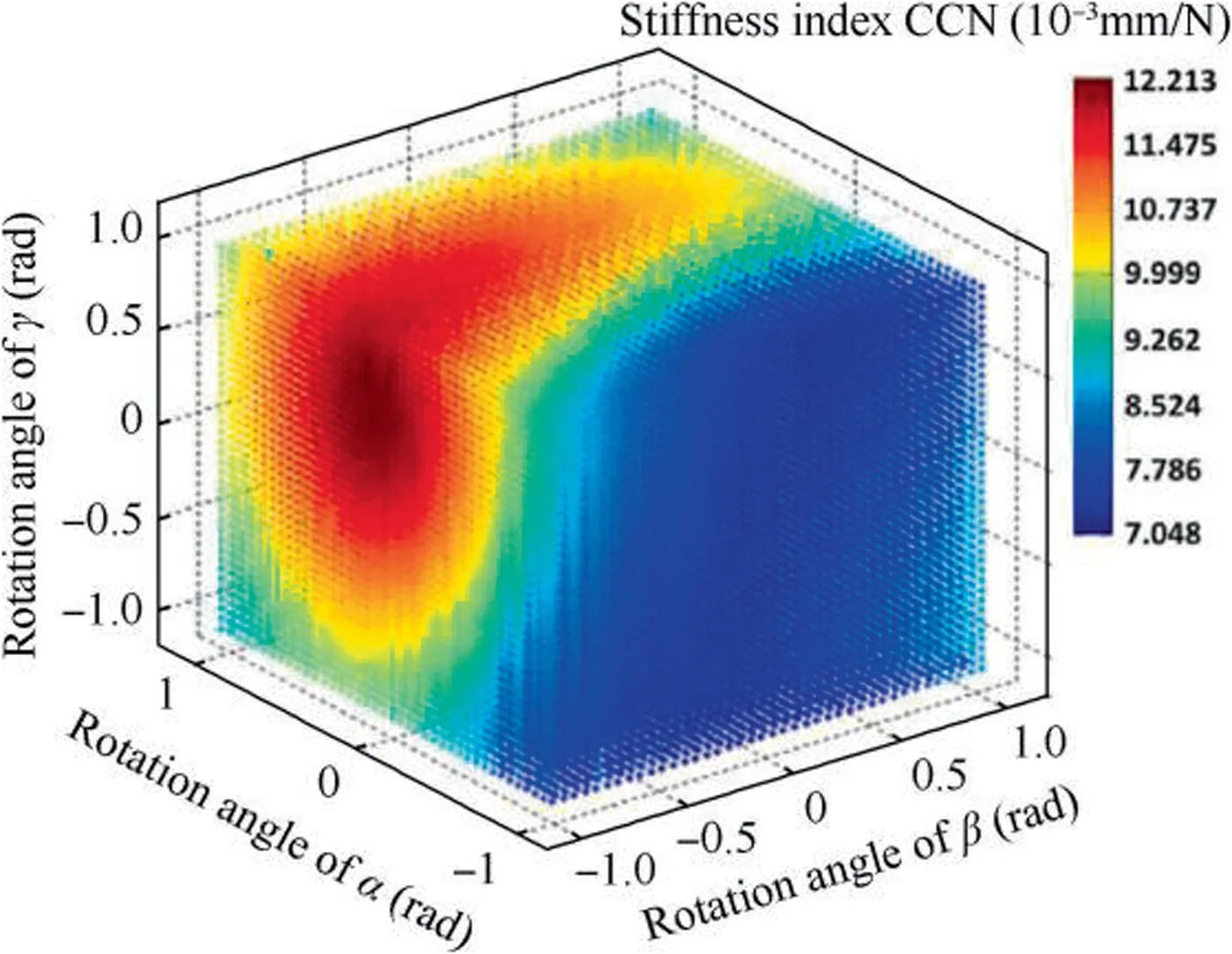
Fig.6 Stiffness index CCN varies with Euler angles in a cutting contact point.77
Compared with grinding,milling has greater dynamic milling force,which requires higher stiffness and dynamic characteristics of the robot.By adding a self-balancing device or a force balancing device to the robot joints,as shown in Fig.7,the stiffness and stability of the robot can be improved,and the spatial distribution of both characteristics can also be changed.Bu et al.proposed a performance index based on pre-load pressure,which was used to evaluate the improvement effect of robot end preloading on robot stiffness,and improve the drilling quality by optimizing robot drilling posture.Nguyen Vu and Kuoproposed the compliant uniformity index,constructed the mapping relationship between torque and positioning error,and evaluated the structural flexibility and comprehensive positioning error of the springhinged robot.The index with different mode is plotted in the workspace of a 2-DOF planar quasi-serial manipulator in Fig.8.
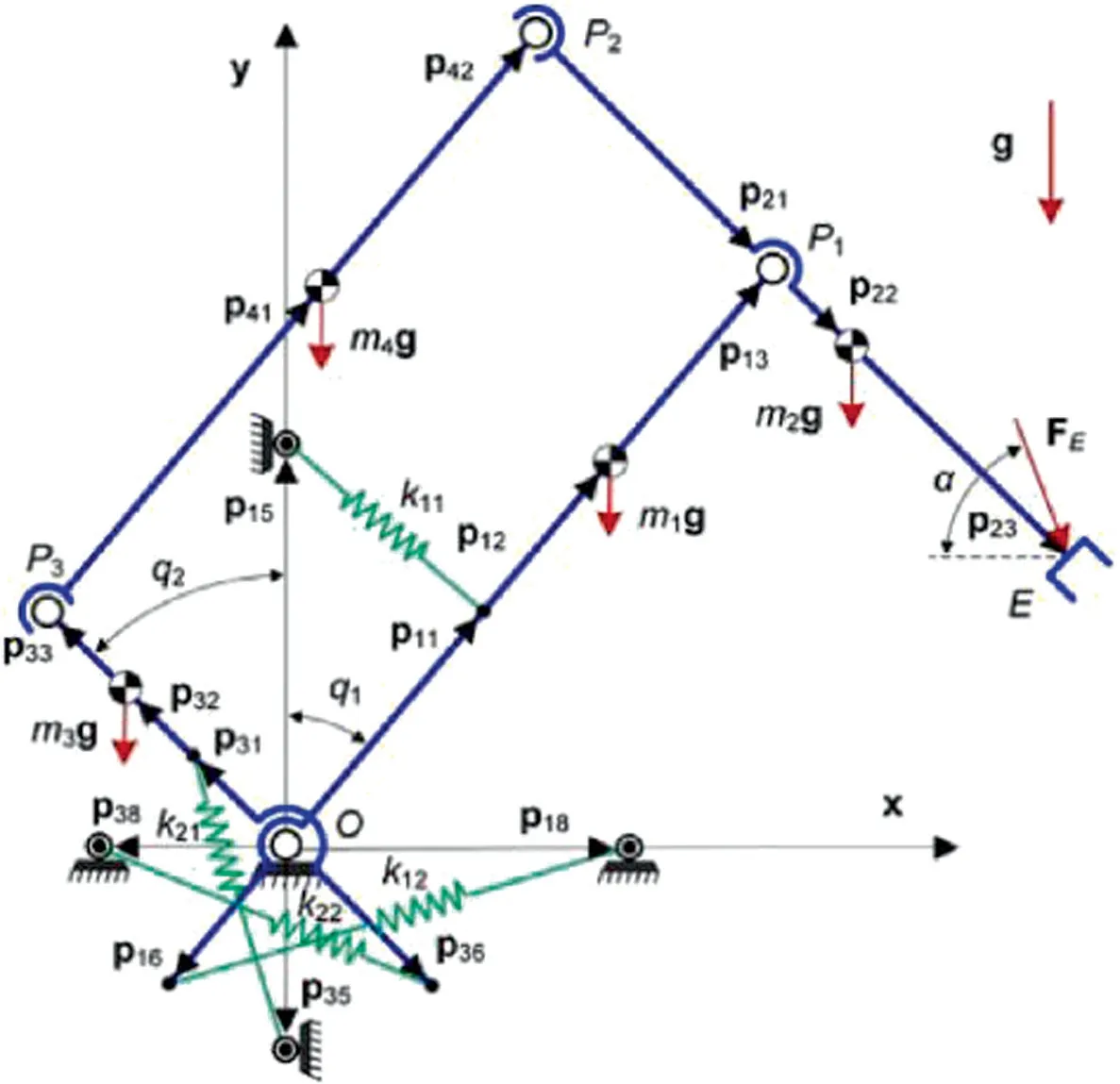
Fig.7 Schematic of 2-DOF spring-articulated planar quasiserial manipulator.64
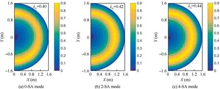
Fig.8 LCUI for 2-DOF planar quasi-serial manipulator.64
3.2.Dynamic behavior of milling robot
In order to obtain the dynamic behavior of a machining robot,there are two main approaches for researchers,structure analysis and experimental tests.
For structure analysis,researchers take the robot as a multibody system,then the tool tip FRF is the superposition of the response of all the substructures.Finite element analysis(FEA)and Hamiltonian methodare the dominant methods in structure analysis.
As a computer-aided engineering technology,the FEA method involves multi-body dynamics,numerical method and software engineering.After decades of development,there is a lot of powerful FEA software,which is of great significance to structural modal analysis.Mousavi et al.established a multi-body dynamic model of a serial robot using beam elements based on the matrix structural analysis(MSA) method,Fig.9 presented the simplified beam elements of the robot.Zhang et al.modeled the complex limb structure as a spatial beam with corresponding geometric cross sections,and simplified the revolute,universal,and spherical joints into the virtual lumped springs associated with equivalent stiffness and mass at their geometric centers.Based on the finite element(FE)method,the natural frequency and corresponding mode shapes of the parallel kinematic machine(PKM)at any typical configuration can be obtained by solving the characteristic equations.Wu et al.proposed a general method for electrodynamic modeling of parallel kinematic machines using substructure synthesis technique.They decomposed the entire robot system into component substructures and joint substructures,which were simplified and modeled using modal reduction technique and virtual springs,respectively.The established motion equation could rapidly predict the static and dynamic behavior of the system with sufficient accuracy.
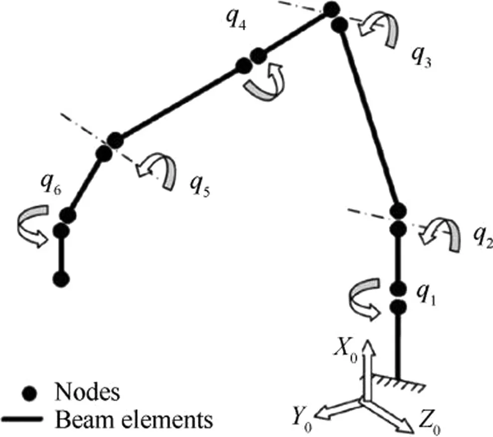
Fig.9 Simplified 3D beam elements model of the robot.89
The most effective dynamic algorithm in the literature is based on the Newton-Euler motion equation,while Leimkuhler and Reichfound that the algorithm based on Hamiltonian regular equation has better parallel computing efficiency,Bayo and Avellonoted that the Hamiltonian form is more convenient to describe the movement of the collision process.They combined augmented Lagrangian method with regular motion equations,proposing an approach to simulate mechanical systems using non-holonomic constraint Hamiltonian method,which was proved to be superior to Newton-Euler algorithm.Chadaj et al.proposed a new algorithm for solving Hamiltonian regular equations in parallel utilizing the divide-and-conquer scheme for the forward dynamic simulation of single open-loop kinematic chain and tree-like topologies systems.Based on kinematics constraints and dynamics constraints,Zheng et al.proposed a parallel recursive dynamic modeling method for the robot with flexible bargroups based on Hamiltonian motion equation and Lagrangian principle,which was applied to Delta parallel robot and KUKA serial robot and showed higher algorithm efficiency and better universality compared with the existing dynamics modeling methods.Based on the modeling of a spatial flexible robot,Mattioni et al.proposed a modular and controloriented model of a double flexible-link manipulator,which consisted of a finite-dimensional nonlinear system describing the actuated dynamics of rotating joints and the power preserving interconnection between two infinite-dimensional systems describing the beam’s motion and deformation.Then,the dynamic equations of the system were derived by choosing appropriate state variables utilizing Hamiltonian principle.
The FEA method is easy to operate and can predict the dynamic behavior of the machining robot in any posture.However,the material parameter settings in the modeling process are often quite different from the real situation,resulting in low accuracy of the simulation results.
For experimental tests,robot equipped with spindle is considered as a whole structure.The parameters accurately reflecting the robotic dynamic behavior can be obtained by the experimental test and modal analysis method.The experimental modal analysis(EMA)method has higher accuracy but more complicated operation,because the experiment can only be conducted in a single posture at a time.It is generally used as the basis for the calculation of robotic milling stability.Through EMA,Mejri et al.conducted frequency response experiments on the tool tip of the ABB IRB6660 robot,including 4 postures in the X axis direction,4 postures in the Y axis direction,and 3 postures in the Z axis direction,to analyze the effect of the robot posture on the modal parameters.Tunc and Shawanalyzed the posture-dependent stiffness and dynamic behavior based on the experimental methods for mobile robots used in the machining of large aerospace parts.Karim et al.used the EMA method to study the dynamic behavior of milling robot,discovering the linear behavior of the Eigen frequencies in parts of the workspace.Chen et al.conducted a lot of impacting tests on the tool tip,and used the inverse distance weighted(IDW)model to predict the frequency response function (FRF) of the tool tip in any posture,as shown in Fig.10.Leonesio et al.determined the static and dynamic flexibility of the robot in different postures through EMA.Urresti et al.used EMA to select appropriate cutting strategies and parameters for high feed milling.Making use of specific modes of vibration dominated by the compliance of only one joint,Doria et al.identified the joint compliances of a serial six-joint industrial robot with a novel modal method.Hao et al.conducted modal experiments on the milling robot,and investigated the low-frequency modes of the robot by modal experiments involving a laser tracker and a displacement sensor,treated that the low-frequency modes as the main part of the prediction error of the zeroth order approximation method,which could be dominant in low-speed robotic milling processing.

Fig.10 IDW model for FRFs prediction.98
The model-based method has the defect of low accuracy,while the experiment-based method cannot directly study the posture-dependent dynamic behavior,being difficult to analyze the advantages and disadvantages of the dynamic behavior of the robot in the workspace.The method combining model and experiment can predict the dynamic behavior of the machining robot in any posture based on the established robotic dynamic model and some experimental data,which is more accurate than the FEA and experimental tests.Therefore,the synthesis of the two methods is of high research significance,which can accurately identify the robot dynamic parameters while predicting and analyzing the dynamic behavior in any posture.
Through the experimental data from the experimental modal analysis of robot components,Mohamed et al.established an updateable dynamic model of the entire robot assembly,replacing the testing on entire assemblies with the virtual testing of modular robot systems.Nguyen et al.presented a Gaussian process regression (GPR)-based approach to model the dynamic behavior of a six-degree-of-freedom industrial robot and conducted verification experiments.Vu et al.proposed a complete modal decomposition and spectrum construction algorithm that can highlight the structural modes and harmonic excitations,which can discriminate,display and monitor the harmonics and structural modes through accurate identification from the vector autoregressive model.In order to effectively identify the parameters of the dynamic model of the 6-SPS parallel-motion manipulator,Ringgaard and Ballingupdated the stiffness and damping of a small set of manipulator poses using operational modal analysis and a two steps parameter identification routine,resulting a model including the dynamic response information in all postures in the workspace.The results showed that the operational modal analysis performed well in estimating frequencies and mode shapes of the symmetric structure,but damping estimates were poor.In order to realize on-line condition monitoring,Maamar et al.used the transmissibility function-based (TFB) method to identify the modal parameters during machining operations through operational modal analysis (OMA).Huynh et al.proposed two multi-body dynamic models of articulated industrial robots suitable for machining.Combining with the established dynamic model of robotic joints and some experimental data,Chen et al.predicted the FRF of the milling robot in any posture using the receptance coupling substructure analysis (RCSA)method,achieving good results in the frequency band of 200-2000 Hz,overview of the method was presented in Fig.11.Combining the multi-input multi-output identification method,the computer-aided design model of the robot,and the EMA,the link and rotor inertias along with the joint stiffness and damping parameters of the established models were identified as shown in Fig.12.Combination of model and experiment,assuming that the link stiffness is much greater than the joint stiffness,only the joint flexibility is considered.Combining theoretical model and experimental data to reduce operational complexity and improve accuracy.

Fig.11 Overview of method for predicting position-dependent tool-tip FRFs.108
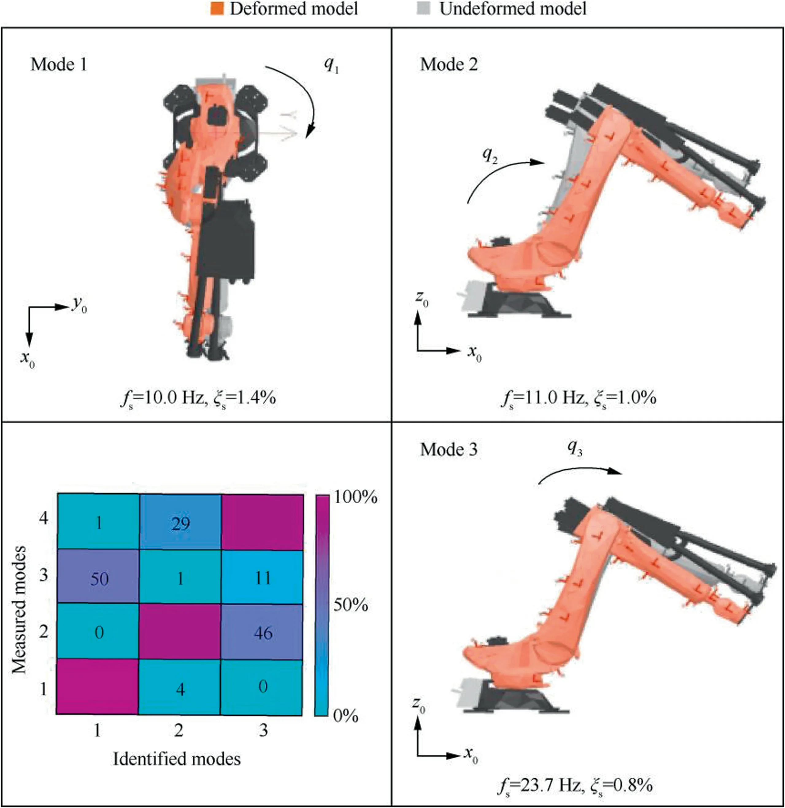
Fig.12 Simulated mode shapes with SDOF flexible joint model for the milling posture.21
Trajectory and parameters planning are of significance to achieve efficient and stable machining.Trajectory planning mainly includes feed direction planning and joint motion(posture)optimization for robot machining.In terms of feed direction and toolpath planning,Tunc and Stoddartconsidering the position-dependent tool tip dynamics,proposed an approach to evaluate and select tool path patterns and optimum feed direction.In terms of joint posture optimization,Mousavi et al.established a functional relationship between the redundancy offered by the kinematic chain and the stability limits in the robotic milling.A selected machining trajectory and the related FRF vibrations are analyzed as shown in Fig.13.Celikag et al.studied the changing trend of high and low frequency modes of the robotic milling system with the robot postures,and analyzed the stability at low and high spindle speeds.Based on this,they adjusted the dynamic behavior of the robot,considering different spindle speeds,by continuously optimizing the robot postures during the milling process.Gonul et al.analyzed the tool tip dynamics along the feed and cross-feed directions,improving the stability of robotic milling by optimizing the kinematic redundancy.
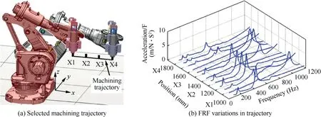
Fig.13 FRF vibrations analysis.89
In terms of intelligent planning with transfer learning,Helwa and Schoelliginvestigated through a theoretical study of single-input single-output systems,and the properties of the optimal transfer maps.This algorithm does not require detailed knowledge of robotic dynamics but simple experimental testing.Devin et al.demonstrated that neural network policies could be decomposed into ‘‘task-specific” and‘‘robot-specific” modules,allowing for sharing task information (such as perception) between robots and sharing robot information between tasks(such as dynamics and kinematics).
3.3.Robotic milling chatter and suppression
Due to the poor rigidity of the robot structure,chatter often occurs during machining with harsh noises emitted,which seriously reduce the machining accuracy and surface quality,as shown in Fig.14.In the research on the modal characteristics of industrial robots,there are two phenomena:one is that the chatter occurs in the high frequency band when using slender tools;the other is that the chatter occurs in the low frequency band when using large diameter tools.In fact,the two phenomena happen by different mechanisms:
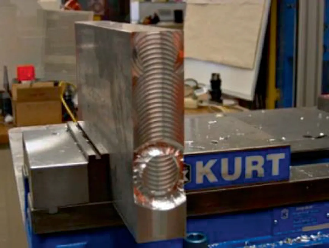
Fig.14 Chatter phenomenon in robotic milling.119
The former is regenerative chatter generated by tool flexibility,occurring between tool and workpiece.Instantaneous chip thickness and cutting force vary due to the phase difference between the ripple left by the previous cutting teeth and the ripple produced by the current cutting teeth.If the increase of cutting force further leads to greater ripple difference,the vibration amplitude will further increase and cause violent vibration,and finally lead to regenerative chatter.From the perspective of control,Mousavi et al.described the feedback loop formed during the regeneration process between the process dynamics and structure dynamics of the robot machining system,as shown in Fig.15.Mohammadia and Ahmadiabelieved that the nonlinear change of milling force caused by axial vibration of robotic milling has a significant influence on regenerative chatter.

Fig.15 Principle of regenerative chatter.89
The latter is the modal coupled chattergenerated when the stiffness of the robot structure is lower than that of the machining process.It is caused by the continuous vibration of the machining system in two or three directions.The chatter frequency is about 10-30 Hz,and the violent shaking of the robot arm can be observed.In the application of robotic milling,Cen and Melkotecontinues the research of Pan et al.,the stability of the system depends on the eigenvalues of matrix A in Eq.(1).When all the eigenvalues are negative real numbers,the system is stable;when the matrix has positive eigenvalues,the system is unstable.

where,andare the maximum and minimum principal stiffness of the robot. Kand Kare the cutting stiffness in theanddirections.β and Kare constant for a specific machining condition.γ represents the angle between the principal direction of the maximum stiffnessand the force vector,V changes with the angle(βγ)and describes the coordinate transformation betweenand,as shown in Fig.16.
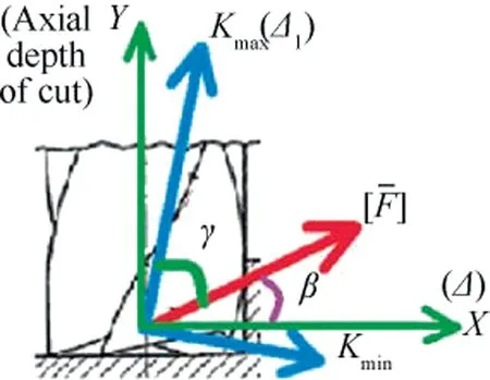
Fig.16 An equivalent 2D model of the robotic milling process.23
In addition,Cordes et al.through the stability verification test of high speed milling of aluminum alloy and low speed milling of titanium alloy,it is pointed out that high speed milling has higher excitation frequency and lower milling force,and regenerative chatter mainly occurs.However,the excitation frequency of low-speed machining is similar to the modal frequency of robot structure,which can easily cause the modal coupling chatter of robot structure.Yuan et al.summarized the chatter characteristics in robotic milling,as shown in Table 4.
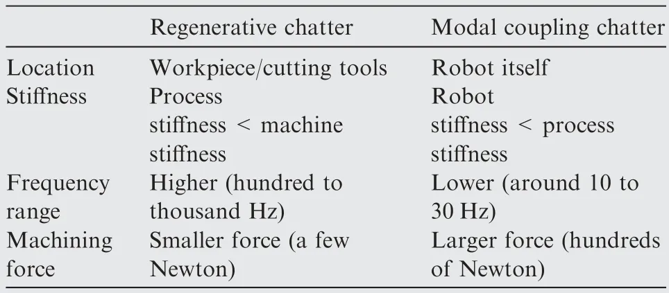
Table 4 Chatter characteristics in robot machining.15
Modal coupled chatter mainly occurs in the robot itself,and has greater vibration amplitude and destructivity than regenerative chatter,which is the first case to be avoided in the milling of robot with complex parts.Gasparetto,,Zhang et al.,and He et al.adjusted the direction of the main stiffness and the resultant cutting force of the robot by changing the feed direction.Based on the stiffness model,the instability criterion considering the modal coupled chatter was established by Cen et al.By controlling the angle γ between the robot’s main stiffness vector and the milling force vector,the maximum feed rate at the critical point is determined,the real feed rate is scheduled synchronously as shown in Fig.17.Celikag et al.improved the milling stability of the robot at low spindle speed by programming the robot’s redundant axis to control its modal coupled chatter.
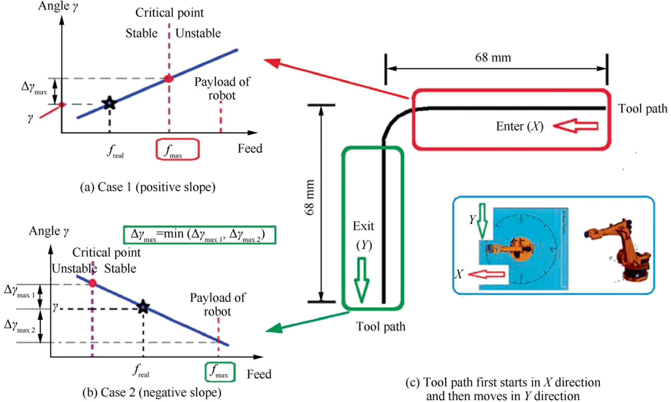
Fig.17 Tool paths and the related feed rates in stable condition of robotic milling.131
Avoiding regenerative chatter is an important means to improve machining efficiency and ensure machining quality when modal coupled chatter is under control.Different from machine tool processing,due to the weak stiffness of the robot and the position-dependent characteristics,the effect of modal coupling must be considered in the SLD of regenerative chatter in robotic milling.Li et al.found that the stable cutting depth value was improved when considering the influence of modal coupling,and a more accurate stability SLD was obtained.Mousavi et al.drew a 3D SLD and verified that the change of robot pose had a significant influence on the SLD.Wang et al.proved that the feeding rate and cutting depth of a specific robot pose are the two most important factors affecting the SLD.
In addition,multi-modal characteristic had been shown a coupling effect on chatter,and are more significant in the robotic processing system.Therefore,it is still necessary to study the influence law of multi-modal characteristics on the robotic processing stability.For the match of robot system with cutting tool,Tunc and Shawinvestigated the interaction between the cutting tool modes and the robot modes in such cases Fig.18,as shown that for tool 1,the chatter mode shifted to robot mode for a very short range of spindle speeds around 5000 rpm.For tool 2,the chatter frequency was always around the tool mode.The chatter frequencies simulated for tool 3 was always around the robot or spindle modes.Therefore,Tunc et al.concluded that tooling was critically important for robotic milling applications.For the match of robot system with the processed material,Cordes et al.conducted several experiments to observe the dominant mode using different work material during robotic milling.For the high speed milling of aluminum,there was no robot structural mode during the test.However,for the low speed milling of titanium,it was shown that the high frequency tool and spindle modes are damped out by the process,and only low frequency robot’s structural modes cause chatter.
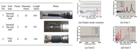
Fig.18 Cutting tool modes and robot modes for different tools.134.
Chatter monitoring and suppression is an effective method to improve the efficiency of robotic milling.Qin et al.adopted two three-direction acceleration sensors to monitor the drilling vibration of the robot,and optimized the position and posture of the sensors.Dai et al.adopted the laser displacement sensor to measure the milling vibration of the surgical robot,the vibration signal is processed by lifting wavelet packet transform,and the milling state of different materials is identified with the method of support vector machine.Yuan et al.designed a dynamic vibration absorber with variable natural frequency based on the property of variable elastic modulus of magneto rheological elastomer (MRE) under different magnetic field strength,as shown in Fig.19.By collecting and identifying the low-frequency chatter frequency of milling and adjusting the frequency of dynamic vibration absorber to form resonance,the modal coupled chatter energy in robot machining is dissipated,and the purpose of semiactive control is achieved.Chen et al.designed a variable natural frequency magnetorheological damper (Fig.20),and set its natural frequency as the frequency doubling of spindle speed to attenuate grinding vibration.Beudaert et al.designed a portable damper for chatter suppression of flexible parts.The main structure of the damper is the eddy current damper,which is fixed on the flexible plate surface by magnetic absorption,and an automatic tuning program is developed which not need the object models to suppress the structural vibration within 20-400 Hz.
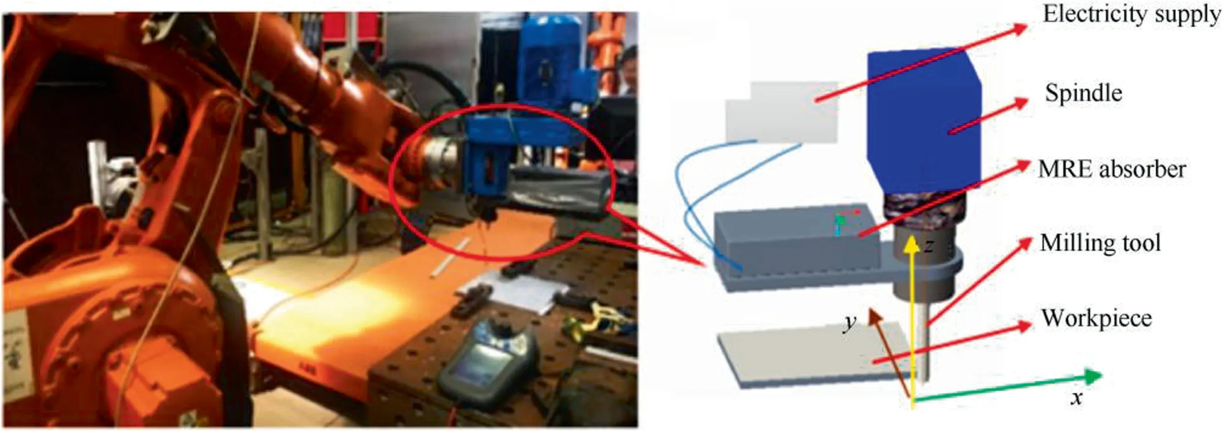
Fig.19 Magneto rheological elastomer vibration absorber.118
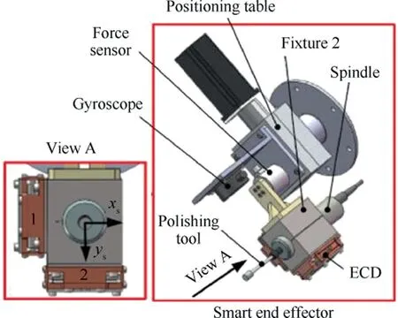
Fig.20 Magneto rheological damper vibration suppression device.
Active workpiece clamping or auxiliary support is an effective method to restrain vibration of thin-walled robotic milling.Sallese et al.pointed out that for high-frequency regenerative chatter,the application of a frequency close to the first half of the tooth-pass harmonic frequency would destroy the regenerative effect.A two-degree-of-freedom workpiece clamping platform is designed and the high frequency regenerative chatter is suppressed by sinusoidal excitation of fixed frequency.Ozturk et al.adopt robot assisted support to improve the static and dynamic characteristics of thin-walled parts during the milling process,reduce contour errors and improve surface quality.Further,Sun et al.verified the significant role of robot auxiliary support in improving the stability of thin-wall parts during milling.
3.4.Robotic milling deformation and compensation
The correlation error related to machining deformation is due to the deviation of the actual trajectory of the robot from the theoretical trajectory under the action of cutting force.Apart from the method based on kinematic calibrationof DH parameters mainly deals with the deviation caused by the robot geometry and assembly,this section mainly review the methods to obtain the machining error of robotic milling,such as sample cutting method,virtual simulation method and online measurement method.
The sample trial-cutting method is to obtain machining errors through trial-cutting,surface measurement,surface reconstruction and alignment..Abele et al.conducted the workpiece alignment with coarse process and precise process,as shown in Fig.21.The comprehensive machining error including positioning error and force deformation error is obtained through the comparison of CAD model and Scanned model,which has the advantage of high precision and is suitable for processing of batch parts.At the same time,due to the high processing cost of samples,offline detection cost and time consumption cost,it cannot adapt to the production rhythm of multi-variety and small-batch processing,and cannot give play to the flexible configuration advantage of robotic milling.

Fig.21 Alignment of Scanned model and CAD model in sample trial-cutting method.144
Virtual simulation methods can be divided into three types according to the relationship between force and deformation:static stiffness method,quasi-static stiffness method and dynamic coupling method.Static stiffness methodis based on robot stiffness model to predict static deformation,and the prediction accuracy depends on the accuracy of the stiffness parameters.Because the dynamic characteristics of the robot are not considered,it is suitable for machining deformation simulation with the spindle speed higher than the robot nature frequency.Quasi-static model prediction presented by Bondarenko et al.is based on robot structure dynamics to achieve the prediction of robot dynamic deformation under specific milling forces,without considering the coupling effect of milling forces and dynamic deformation.It is generally used to predict the step response vibration caused by sudden change of milling force during the process of cutting in and cutting direction change.The coupled dynamic modelis based on the robot structure dynamics.Considering the interaction between the dynamic deformation of the robot and the milling force as shown in Fig.22,the machining deformation error is predicted,and the prediction accuracy depends on the dynamic parameters and the precision of milling forces.Considering the interaction coupling between milling force and dynamic deformation,it can be used to predict the general vibration displacement in the process of robotic milling.The accuracy of virtual simulation model prediction method depends on the accuracy of static stiffness model,robot dynamics model and machining process simulation model.Model parameters such as stiffness,mass,damping and milling model parameters are very important.These are usually calibrated off-line and can be used to describe the change of deformation rules for process optimization.Aiming at the accurate prediction of machining deformation of complex parts robot,due to the nonlinear problem of model caused by changeable machining features and the uncertainty of model parameters,these off-line models are unable to obtain the state information of environment and robot,and their prediction accuracy are insufficient.

Fig.22 Coupling of models:robot structure and milling process.52.
Online perception and measurement methods are mainly used to monitor the terminal deviation of the robot through posture sensing devices,such as binocular vision,laser trackerand indoor GPS.At present,several typical robot positioning error measuring methods are shown in Table 5.From the technical parameters,the laser tracker may have the best sampling frequency and measurement accuracy,up to 1000 Hz/15 μm±6 μm/m for Leica Absolute Tracker AT960;Indoor GPS has multi-sensor layout which can be dynamically reconstructed and has the maximum flexible measuring range.For the sensing and monitoring of the milling trajectory of the robot,indoor GPS appears to be inaccurate (position error 380 μm and posture error 0.01°),the measurement system based on vision and laser tracker is more suitable.The above method is expensive and only applicable to the robot machining environment with no shielding.It cannot adapt to the processing monitoring for complex parts with shielding and narrow cavity parts.
The compensation strategies for robot trajectory deviation caused by milling deformation mainly include off-line compensation in process planning stage,model+sensor data based compensation in post-processing stage and online compensation in motion execution stage.The approach,rate,main cost and capability of different compensation types are shown in Table 6.
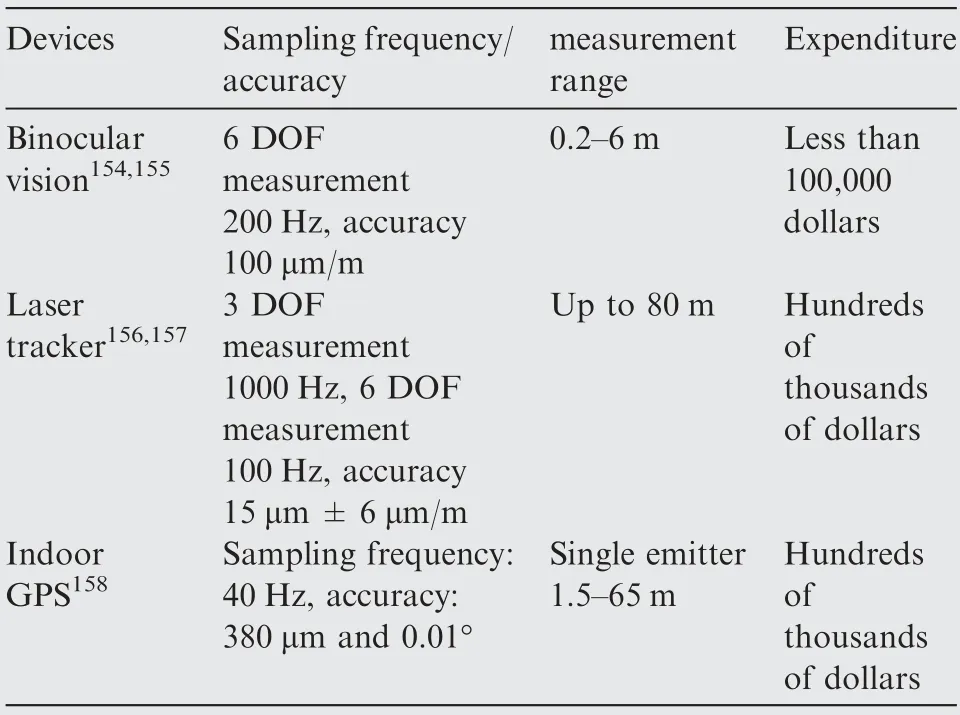
Table 5 Several typical robot positioning error measuring methods.
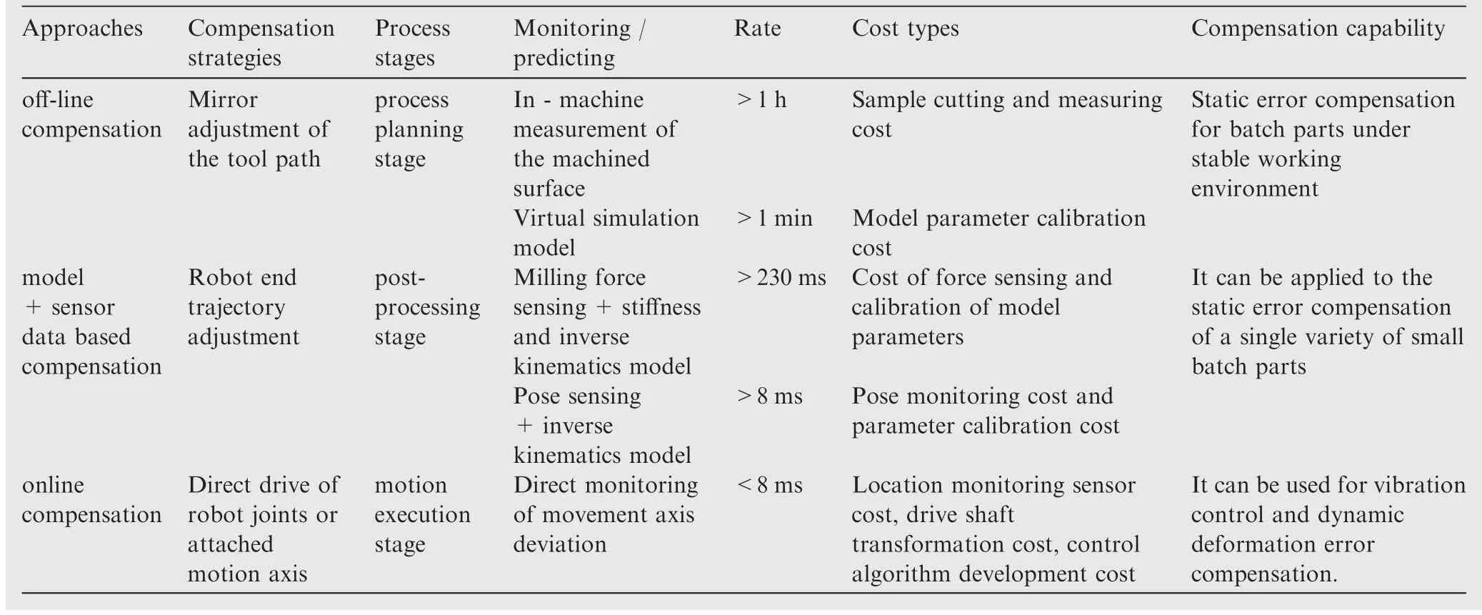
Table 6 Compensation strategies for robot trajectory deviation.
is usually realized by mirroring offset of tool path in the process planning stage,which is a simple and effective method to improve the precision of robotic milling trajectory.According to the error acquisition method,the off-line compensation strategies can be classified as follows:Off-lineor in situmeasurement method of sample tried-cut surface,which can obtain trajectory error for subsequent processing by measuring error distribution of sample tried-cut surface,as shown in Fig.23.This method can achieve good results for batch processing of the same part.The historical processing data based method presented by Kruger et al.monitors and acquires the state information of the workpiece in the processing process.Combining with the error distribution of the processed part,the mapping relationship between the processing state and the processing error is constructed to realize the compensation of subsequent processes.This method can compensate the workpiece with the same type and different size.Virtual simulation modelpredicts and compensates deformation errors at different machining locations through milling force and robot stiffness model.This method relies on model prediction accuracy.Although it can be applied to any machining process that can be modeled,it has poor accuracy adaptability under different working conditions.In short,the off-line compensation method does not need to integrate external force or posture sensing system,and it is low cost and suitable for static error compensation of batch parts processing in stable working environment.
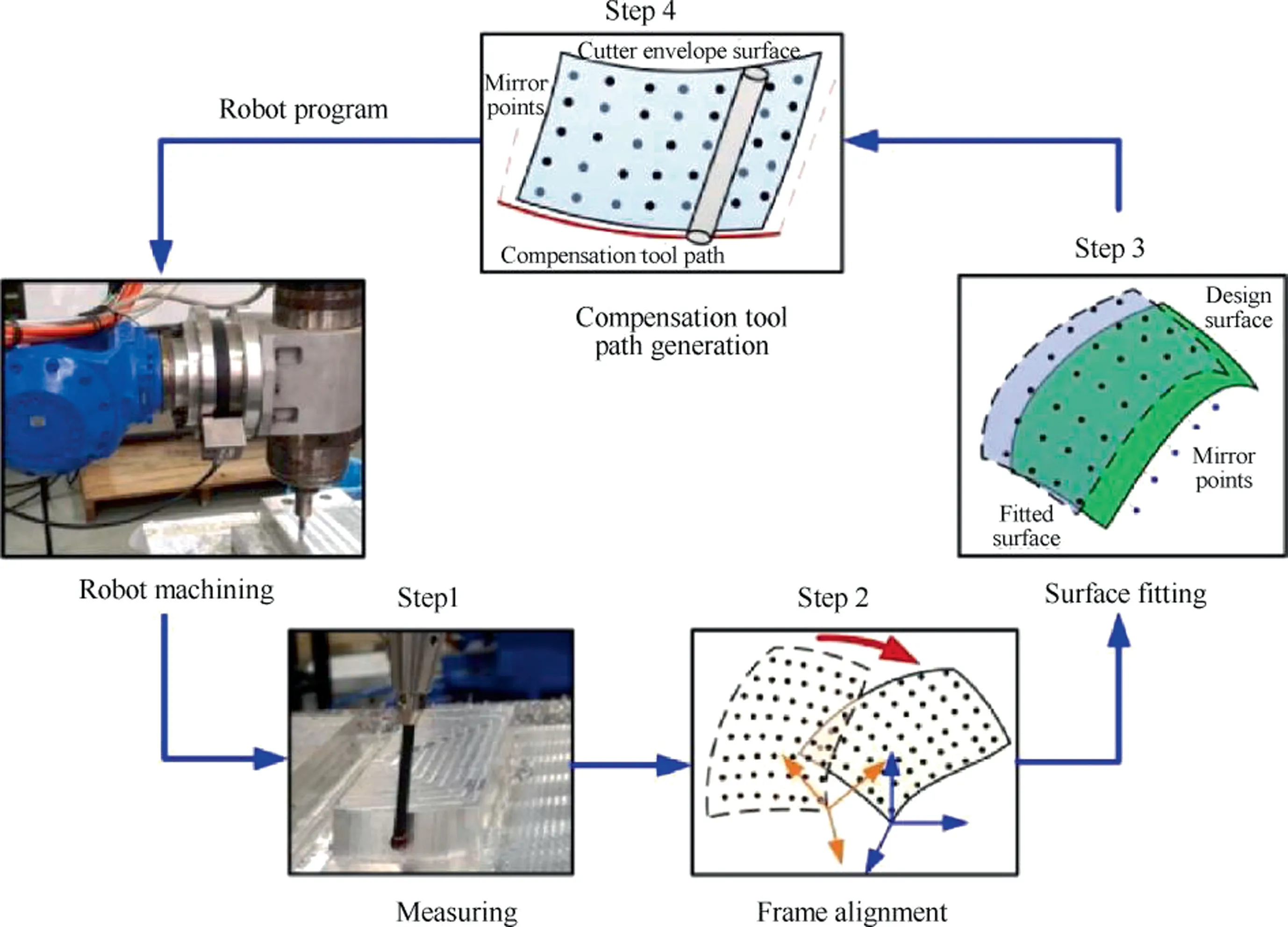
Fig.23 Off-line compensation strategy of robot machining based on measuring error in situ.145
is achieved through milling force sensing or posture sensing to obtain the trajectory deviation of the robot end.The joint deviation compensation is calculated by Zhang et al.online through the inverse kinematics model (equivalent to the postprocessing process considering the deviation),and the joint deviation compensation is made when the robot executes the next cutting cycle.According to the acquisition method of robot end trajectory,the model+sensor data based compensation can be divided into the following two types:One is through the monitoring data of milling force and stiffness modelto obtain the end-effector trajectory deviation,as shown in Fig.24.Through experiments,Weipointed out that this method need to guarantee the time between two adjacent cutter locations is not less than 230 ms,of which 200 ms for the milling force data acquiring,30 ms used for obtaining the robot pose from the robot system and other state data.The other is to obtain the terminal deviation of the robot by online sensing,mainly through laser tracking instrument,binocular vision,etc.Möller et al.used stereo camera system to achieve the dynamic absolute positioning accuracy of 0.1 mm,which is much higher than the trajectory accuracy of the robot.Moeller et al.linked robot system and measuring equipment through the developed UCI-APP,this method can achieve high-speed monitoring of 8 ms and the trajectory error is reduced to within 0.3 mm.Based on the robot’sterminal pose deviation monitored by laser tracker,Shi et al.compensated the robot’s trajectory error through KUKA RSI,which improved the robot’s positioning accuracy to 0.8 mm and posture accuracy to 0.01°.The online compensation method based on model+sensor data requires additional integrated force sensing or terminal pose sensing and signal processing system,which has strong environmental adaptability but high cost and is suitable for quasi-static error compensation under high-speed milling of soft materials.
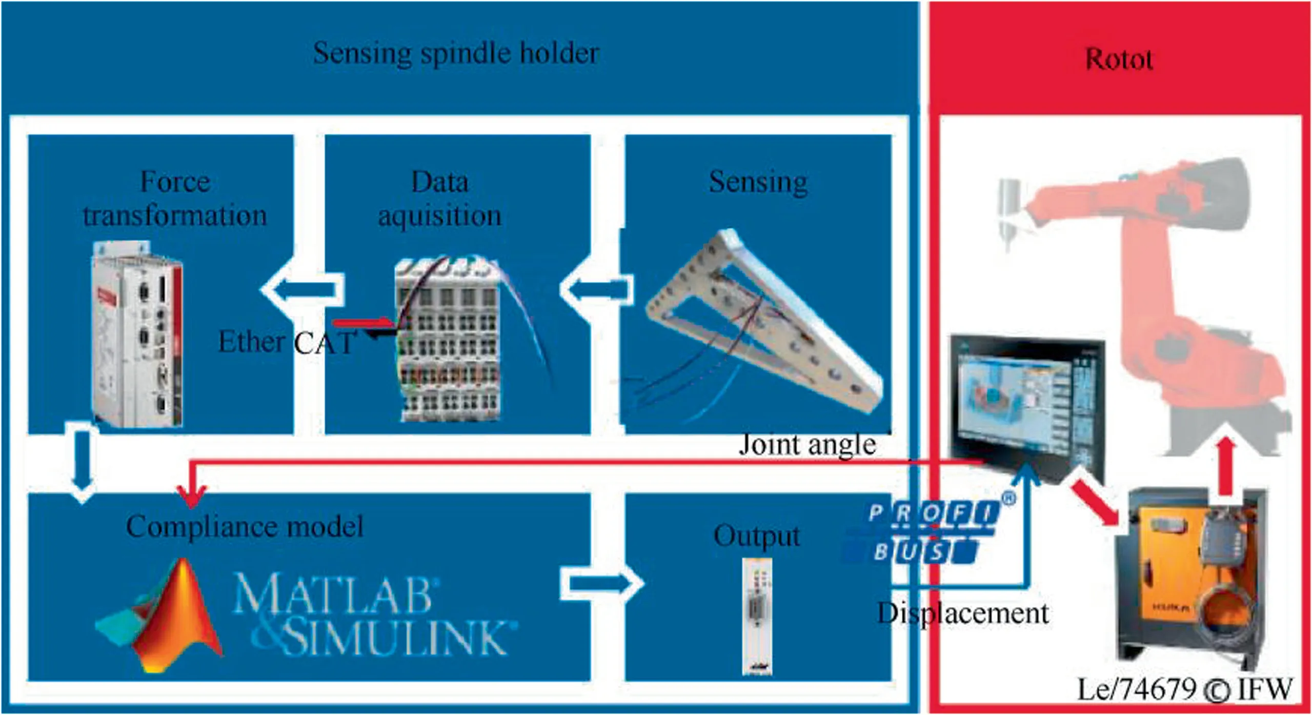
Fig.24 Error compensation strategy based on milling force monitoring.167
usually directly adjusts the motion of the joint axis or additional axis of the robotic milling system.Three categories can be classified according to the position of the motion axis.As a compensation device,the joint of the robot is equipped with position sensors by Denkena et al.on the load side,such as encoder and grating ruler,to detect the deviation between the actual and theoretical position,and to correct the motor drive signal.The method presented by Vieler et al.had a very high dynamic response precision,could compensate the dynamic deviation,and improve the stability boundary and positioning accuracy of the milling robot.While,it is still in the research stage in the laboratory and has not been widely used.Chen et al.utilized the auxiliary compensation device at the end of the robot to correct the trajectory deviation of the robot through the micro-platform installed at the end of the robot.This method is limited to the load capacity of the robot,and is mainly used in low-force processing conditions such as grinding,trimming,deburring and other floating processing conditions based on the surface characteristics of the workpiece.It can also be used for low force milling.Schneider et al.utilized the clamping compensation device of the workbench to correct the trajectory deviation of the robot relative to the workpiece by means of a micro motion platform installed on the workbench,such as a piezoelectric bimorph actuatoras shown in Fig.25.It can be used as a robotic milling platform for non-large parts with high dynamic deformation and error compensation capability.
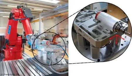
Fig.25 Compensation device based on micro motion workbench.164
4.Trends in robotic milling technology
With the development of the equipment used in extreme environmental equipment,such as deep space,deep sea and nuclear environment,in-situ processing and remediating of parts will be the development trend for ensuring the installation accuracy and improving the processing efficiency.Due to its large mass and volume,high requirements for installation accuracy,long installation cycle and other factors,CNC machine tools are difficult to be quickly arranged in the processing site,and its limited operating space is difficult to meet the requirements of the large processing scope in the processing site.Due to the advantages of small size,light weight and large processing range,the robot can be quickly arranged in the processing site,and can realize the unmanned intelligent processing of parts in the extreme environments by combined with the reconstruction of the unstructured environment,perception technology,remote operation technology,etc.At present,the robotic milling used in extreme environment usually focus on the low precision and small constant load,such as 3D printing,grinding and cutting.For example,Fig.26 (a),Tethers Unlimited Company is studying the robot project of NASA,which can makes the antennas,solar panels and other large equipment in space.Fig.26 (b),Made in Space Company has proposed using robotic arms to 3D print Space parts in orbit around the earth.Fig.26(c),Toshiba has developed a robot with the capable of cutting pipes for the Fukushima nuclear power plant in Japan.
For the high precision milling with the alternating and strong load,as seen in Fig.26(d),HUST is developing a robot system for the repair of large hydraulic turbine blade at the site of the hydropower station.In the future,the robotic milling processing in situ will become a trend for the space equipment,oceangoing ships,nuclear power parts,etc.In the extreme environments,there are strong interactions between robots and robots,between robots and structured or unstructured environments,so the milling of robots will face new challenges.
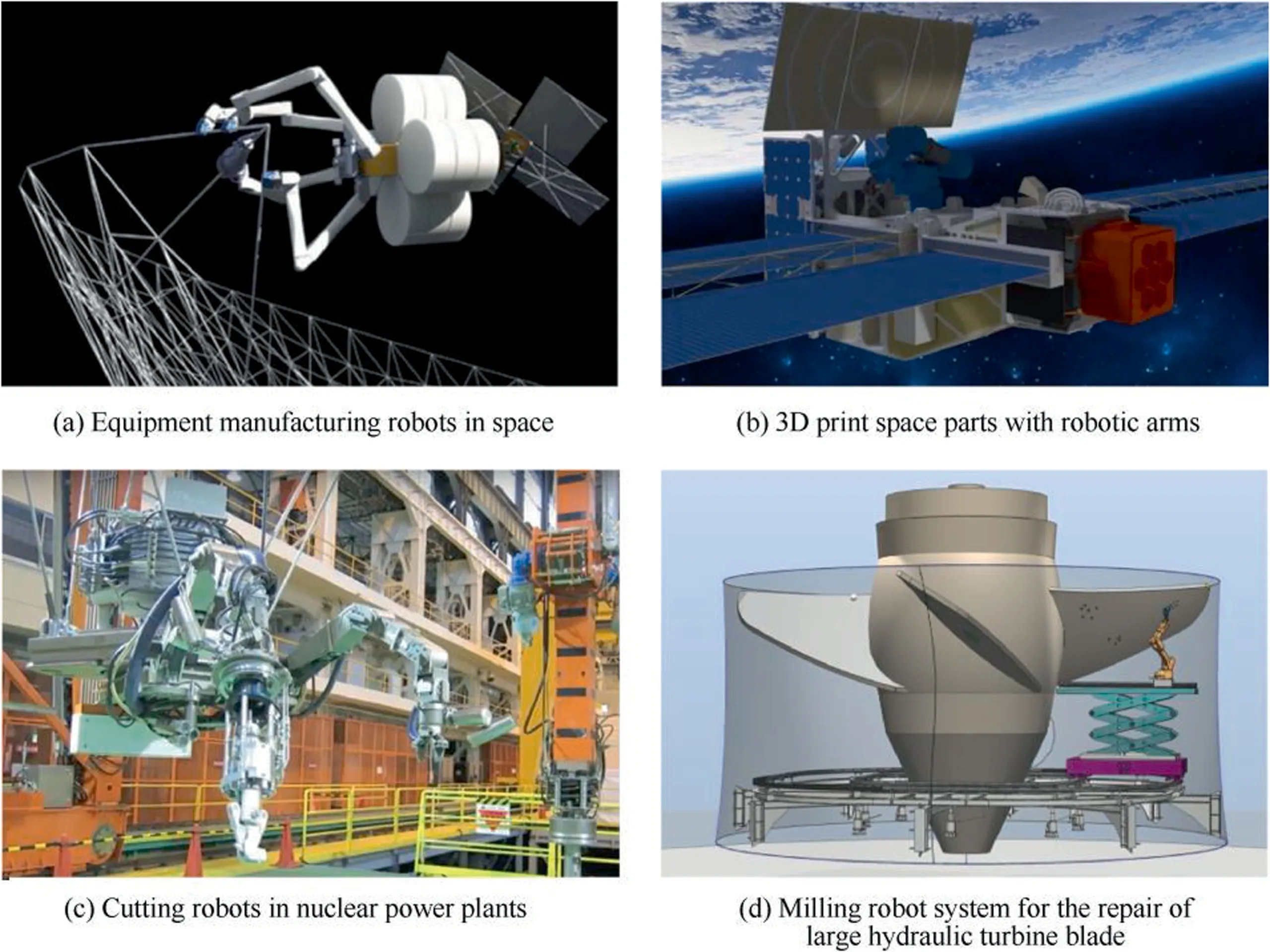
Fig.26 Robot in-situ processing.
4.1.Coupled dynamics of robotic milling
In the extreme processing environment,multi-robot usually need to cooperative milling for a task due to human can’t arrived in situ.At present,the research on the dynamics of multi-robot milling mainly focuses on the single robot,and ignores the influence of the interaction of different milling positions of multi-robot on the dynamic characteristics of the whole machine process system.However,for large structures,especially the thin-walled parts,the dynamic characteristics of the robot and the workpiece need to be considered at the same time.So in order to better control the vibration of large structure under multi-robot cooperative milling,dynamic characteristics change law of the multi-robot milling system should be studied further for the theoretical guidance of trajectory and process parameters planning.
In the extreme environment,there will be narrow and multiobstacle working condition.In the narrow multi-obstacle machining workpiece,the redundancy of the traditional 6-DOF industrial robot can no longer meet the requirements,so the multi-DOF actuator needs to be configured at the end,which constitute a multi-redundant robot machining system with lower rigidity and more complex pose.In order to make the multi-redundant robot suitable for milling in narrow space,it is necessary to study the relationship between the dynamic characteristics and robot configuration,establish the high dimensional stability boundary diagram with multiparameter,propose the process parameters and process trajectory planning method with considering the constraints of obstacle avoidance geometry and smooth movement.In addition,there will be a weightless environment in the in-situ manufacturing in space,and the modal parameters of the robotic milling system will change significantly and influence the vibration response.Moreover,in the in-situ milling in space,there will be a weightless environment,and the modal parameters of the machining process system of the robot will change significantly,thus affecting the vibration response of the machining.In the in-site milling of nuclear power plant,ocean-going ship and water turbine,the base of the robot is relatively weak rigidity,so it is necessary to consider the influence of the base on the dynamic characteristics of robotic milling system.
4.2.Robotic milling with new measurement method and multisensor data fusion
With the development of new measuring instruments,the vibration and deformation of robotic milling process can be measured directly.For example,traditional measurement of robot structure mode is that a large number of acceleration sensors are mounted on the robot,and the excitation is carried out to obtain the modal response signal.On the one hand,time and labor are consumed;on the other hand,the robot structure mode is influenced by the mass of acceleration sensors significantly.The non-contact 3D scanning Doppler vibrator can measure the vibration mode of robotic milling system on three directions automatically and rapidly,and can avoid the influence of additional mass on the measurement results.When the complete vibration mode of robotic milling system are obtained,the weakness part of the robotic milling system can be analyzed deeply and vibration of the robot body structure in the milling can be avoid effectively.Moreover,the movement of cutting tool,workpiece and cutting chip can be observed clearly by using the high-speed cameras.Therefore,the changes of the cutting chip marks,cutting tool and workpiece vibration under the processing status of forced vibration,regenerative chatter and the modal coupling chatter can be analyzed deeply.And the robotic milling vibration with considering nonlinear factors can also be investigated visually.
The Traditional research on robotic milling is usually carried out by establishing the theoretical prediction model which is difficult to achieve accurate modeling for some nonlinear and complex conditions,such as the modeling of robot body structure and the modeling considering the influence of unstructured environment.With the development of sensing technology(force sensing,vision sensing,temperature sensing,etc.),data transmission technology (5G) and data processing technology,multi-source sensing and big data fusion will be an effective method to improve the milling efficiency and accuracy of robot.Multi-source data application in robotic milling can be combined with the theoretical models.Such as in the analysis of robot dynamic characteristics,chatter and deformation error,the using of machine learn in dealing with uncertainty factors of multi-source data can has certain direction and pertinence by combining with the existing deterministic theory prediction model.And then the data processing efficiency and precision of the machine learning can be improved significantly.In addition,all kinds of sensors can be arranged on the robotic milling site,and the data of input (cutting parameters etc.) and output (vibrational state,and error,etc.) is acquired and transferred by the 5G wireless network.And thus the data processing algorithm can be modified according to the requirement of machining vibration and error,and the large-scale process database can be established,which provide the data foundation for high-precision and efficient of robotic milling.
5.Conclusion and future research interests
In view of the characteristics of weak stiffness,low-order dynamic characteristics and pose dependence characteristics of robots,the deformation,vibration and consistency of machining caused by large dynamic cutting forces in milling cannot be avoided.These problems are not prominent in low force machining applications such as grinding,polishing and deburring.For high efficiency and high precision robotic milling,this paper summarizes the relevant research methods and results from the following aspects:the robot stiffness characteristic modeling and its working space planning,the robot dynamic characteristic modeling and machining trajectory planning,the chatter mechanism of robotic milling and weakening control method,the robotic milling deformation mechanism and the error compensation strategy.The research progress of relevant aspects in recent years are summarized,and further development trends are discussed.Based on this development trend and legacy challenges,future research for robotic milling may include:
· Combined with vision and force sensing,the robot pose adaptive adjustment based on migration learning can improve the fast adaptive ability of intelligent processing of complex multi-feature parts.
· A dynamic parameter identification and dynamic characteristic simulation system integrated with on-line motion state monitoring,analysis or simulation model is used to calculate the robot’s motion trajectory and improve the accuracy of the machining trajectory.
· The early characteristics and evolution conditions of chatter generation are extracted to avoid destructive vibration and improve the stability of milling system.
· An efficient time-domain method is studied to improve the accuracy of dynamic deformation prediction through realtime update and calculation of robot dynamic parameters,workpiece characteristics and machining process.
· The online updating method of model parameters of integrated sensor data is developed to improve the precision of robotic milling of complex parts through accurate prediction and prospective compensation of dynamic deformation.
This paper reviews and discusses the challenges,strategies and development of robotic milling from the perspective of process planning and process control.It is expected to promote the application of related theory and technology in high efficiency and precision intelligent robotic milling.
The authors declare that they have no known competing financial interests or personal relationships that could have appeared to influence the work reported in this paper.
This research has been supported by National Science Fund for Distinguished Young Scholars of China (No.51625502);Innovative Group Project of National Natural Science Foundation of China (No.51721092);Innovative Group Project of Hubei Province of China (No.2017CFA003).
 Chinese Journal of Aeronautics2022年2期
- Chinese Journal of Aeronautics的其它文章
- Pressure-induced instability and its coupled aeroelasticity of inflated pillow
- Adjoint boundary sensitivity method to assess the effect of nonuniform boundary conditions
- Transit time difference and equal or non-equal transit time theory for airfoils with lift
- A boundary surrogate model for micro/nano grooved surface structure applied in turbulence flow control over airfoil
- Nonlinear uncertainty quantification of the impact of geometric variability on compressor performance using an adjoint method
- Review on anti-loosening methods for threaded fasteners
