A boundary surrogate model for micro/nano grooved surface structure applied in turbulence flow control over airfoil
Liyue WANG ,Cong WANG ,Shuyue WANG ,Sheng QIN ,Gng SUN,* ,Bo YOU ,Yongjin ZHONG
a Department of Aeronautics &Astronautics,Fudan University,Shanghai 200433,China
b Department of Material Science,Fudan University,Shanghai 200433,China
c AECC Commercial Aircraft Engine Co.,Ltd.,Shanghai 200241,China
KEYWORDS Boundary modeling;CFD;Drag reduction;Flow control;Microstructure
Abstract The application of grooved surface structure is an emerging and effective means in turbulence flow control.However,for a realistic configuration,the global flow field described directly by simple application of massive grids makes it unfeasible to simulate.In this paper,a boundary surrogate model reproducing the effect of microscopic near-wall region is proposed to improve computational efficiency.The surrogate model trained with Lattice Boltzmann Method(LBM)considering the rarefied effect based on real micro/nanoflow field is new among literature,which accurately shows flow characteristics of the micro/nano structure.With this approach,numerical simulations via Reynolds-averaged Navier Stokes equations with modified wall boundary condition are performed in subsonic and transonic flow.The results show that micro/nano grooved surface structure has the effect of delaying transition from laminar to turbulence,thus reducing the skin friction significantly.Analysis of turbulence intensity and turbulence kinetic energy shows that the near-wall flow field of grooved airfoil is more stable compared with that of the smooth airfoil.The reducing rate of maximum turbulent intensity reaches 13.39%.The paper shows a perspective for further application of micro/nano groove structure to turbulence flow control in aircraft design by providing an accurate and efficient simulation method.
1.Introduction
In recent decades,fluid mechanics scholars have been working on the development of effective drag reduction methods for the purpose of energy conservation and emission limitation.Inspired by the dentate riblets over shark skin,microstructure in the surface has become a promising passive flow control technique that requires no additional equipment or energy consumption:its textured surface structure delays the transition from laminar flow to turbulence flow by modifying flow in the near-wall region,thereby reducing the skin friction.
The drag reduction effect of microstructure in laminarand turbulence flowhas been demonstrated by extensive numerical simulations and experiments.Due to the requirement of fine structure and high complexity in industrial manufacturing,the drag reduction technique using microstructure surface has faced challenges in engineering applications for long.However,with the development of coating technology,low-surface-energy coatings are able to attach to the surface,which provides a new solution of improving the efficiency of design and production.In the authors’ previous work,experiments have been conducted to apply microstructure coating technology to airfoil for drag reduction.Tao and Sundesigned low-surface-energy micro/nano coatings with different geometries and verified the effects on transition position and skin friction by wind tunnel tests.The results showed that there is a certain delay in the transition position and a reduction in the drag of the airfoil with coating at both low and high Reynolds numbers.
However,for the simulation of micro/nano structure considered only within viscous sublayer,it is extremely difficult to evaluate the aerodynamic performance of the airfoil by numerical methods.In this paper,we develop numerical methods for airfoil with micro/nano structure in the surface to balance computational resources and accuracy.If the entire flow field is directly described by grids,massive grids are required during the numerical simulation due to the large gap in scale,which is computationally expensive and extremely difficult to achieve in practical applications.To solve this problem,modified turbulence model or the surrogate model of micro/nano structure in the boundary are needed.Zhang and Chenfirst applied wall-resolved LES and the numerical dissipation of advection scheme to the study of riblets on an airfoil,showing that Reynolds stresses and turbulent structures are thereby suppressed in most regions of the upper surface of the airfoil,especially at locations where the pressure gradient is at its maximum.Aupoix et al.proposed turbulence models applicable to flow field with U-riblet and V-riblet based on experimental data and analyzed the drag performance,where the variation of the wall unit velocity profile is used to represent the variation of the wall turbulence structure.Koepplin et al.modified the riblet model for application in impeller machinery,considering the misalignment of the riblets relative to the flow and adverse pressure gradients,which is validated with experimental values for the NACA6510 compressor impeller.However,this modeling relationship is obtained on the basis of a large amount of data,which is relatively inconvenient to apply in engineering problem.Mele and Tognaccinimodified the classical Wilcox boundary condition for rough walls and modeled riblets as singular roughness problems.Later,Mele and Tognacciniused this method to simulate a complex wingbody configuration and then to evaluate the overall effect of riblets on aerodynamic performance.However,the model is based on isotropic properties and is not suitable for the case where a relative angle between the riblets and the inflow exists.Therefore,the slip length model for characterizing riblets was proposed to solve the problem.Navierfirst proposed linear boundary conditions under slip flow.In 1879,Maxwellproposed that the tangential velocity component of a surface could be related to the shear rate by means of a ‘‘slip length”.Mele and Tognaccinifirst developed a boundary equation for the relationship between slip length and riblet height in a RANS solver.However,all of the above boundary models in the mentioned literature cannot reproduce the near-wall flow.In order to accurately convey realistic near-wall flow information,a boundary surrogate model for micro/nano groove structure trained by extensive microscopic simulation data is necessary.
This paper is organized as follows.In Section 2,the boundary surrogate model for micro/nano grooved surface structure is proposed and the accuracy of the model is verified.In Section 3,the aerodynamic performance of the grooved airfoil is compared with that of the smooth airfoil by quantitative analysis.In Section 4,some conclusions are drawn according to the results and analysis.
2.Boundary surrogate model for micro/nano grooved surface structure
2.1.Effect of groove on mean flow


On the grooved surface,the logarithmic law is modified as

where Δcharacterizes the velocity correction.Progress has been made in the early works of velocity correction caused by riblet or groove in the surface.Aupoixreproduced the shift as a function of the riblet geometry,characteristic Reynolds number as well as orientation,and modified the turbulence model to achieve the excepted shift.Mele and Tognacciniintroduced the slip flow boundary condition at the wall to model the drag reduction riblet structure,which offered the method of simulating riblets in the surface in the presence of pressure gradient.The existing riblet models are in common in the aspect that a given riblet corresponds to the constant Δin one case.However,the local Reynolds number and the flow direction relative to the groove at different positions of the airfoil are different,which cannot be ignored.Therefore,the velocity profile corresponding to one grid in the first layer grid above the wall is taken as a unit much closer to real flow,and then Eq.(3) is improved as

whererepresents the grid number of the airfoil surface distributed along the chord length andrepresents the total grid number of the airfoil surface distributed along the chord length.
2.2.Domain decomposition of global flow field
As shown in Fig.1,in order to simulate the global flow field domain Ω of airfoil cover with micro/nano groove structure,a domain decomposition methodis used to solve this multi-scale problem.Ω⊂Ω indicates microscopic near-wall region with artificial inner boundary(the first grid point above the wall) Γlocated within the viscous sublayer.Γis the actual boundary.Then we divide the global problem into two problems:(A) a microscopic near-wall region is replaced by surrogate model of micro/nano grooved surface structure based on the microscopic simulation data;(B) a global flow is solved in the whole domain Ω with modified wall boundary condition based on surrogate model.
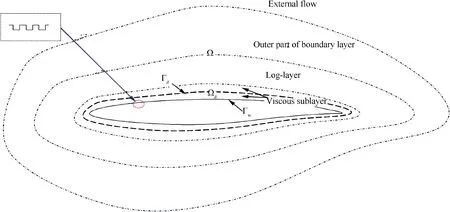
Fig.1 Domain decomposition of global flow field.
2.3.Simulation method in microscopic near-wall region
In the global flow field,a boundary surrogate model(i.e.,wall function)is used instead of the micro/nano groove structure in the surface.The boundary surrogate model is derived based on a large amount of microscopic simulation data.In this section,we introduce the simulation method in microscopic near-wall region considering rarefied effect.
In the numerical simulation of computational fluid dynamics,the degree of rarefaction of gas is judged by Knudsen number.For the flow around the micro/nano groove near the wall,can reach more than 0.01,at which the continuity assumption is no longer in effect.Lattice Boltzmann Method(LBM),a typical method for numerical simulation of incompressible fluids,the governing equation for which is the Boltzmann equation in statistical mechanics,is chosen as the simulation method in microscopic system under rarefied condition.LBM can handle high Knudsen number flow regime because of inherent kinetic nature involving no continuum assumptions.LBM is an explicit method with good parallelism,and can effectively save computational resources when calculating in microscopic region.
The simplified Lattice Boltzmann-BGK equationis as follows:

The LBGK equation can be approximated and discretized as


The equilibrium distribution function is linearized in D2Q9 as follows:
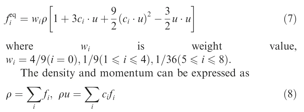
The kinematic viscosity of the fluid ν is given by

In this paper,the total dragcan be expressed as

whereis the force on the wall.
In this paper,for accuracy of time solutionsand acceleration of calculation speed,the fourth-order Runge-Kutta scheme is used to discretely solve the time term of LB Eq.(1),which can be written in the following form:

Integrating Eq.(8)with respect to the timewith the explicit fourth-order Runge-Kutta scheme,one can obtain the following:

In gas micro/nanoflows,simulation of flows under rarefied effect requires appropriate modifications of the relaxation parameters using LBM.This is due to the exchange of momentum between gas molecules and the interaction of gas molecules with the wall,which is influenced by rarefied effect and microscopic geometry.The dynamic viscosity of gas significantly reduces due to rarefied effect.Therefore,a general form of the variation of effective viscosity withwas proposed,which is applicable to a wide range of:

For the rarefied coefficient(),many models have been proposed.In this paper,we select()=.The effective dynamic viscosity is modified as follows:

Taking the effective viscosity and effective density into account,the modified effective relaxation time is as follows:

An important issue about using LBM to simulate the micro/nanoflows is boundary condition.When a continuous medium flow is simulated,a standard bounce back scheme is commonly used to realize non-slip boundary condition.The non-slip boundary condition is no longer applicable when gas molecules slide on the wall under rarefied condition.Therefore,the slip boundary condition is critical for the accurate prediction of rarefied gas flows at micro/nanoscale.In order to obtain proper slippery velocity,a combination of standard bounce back scheme and specular reflection scheme is usedto set the slip boundary condition.The wall boundary condition is expressed as

where ris a weighting factor that measures the contribution of standard bounce back and specular reflection.Here,we set r=0.8.
Since we focus on near-wall flow,symmetric boundary conditions are set at the top in order to prevent interference of the top boundary and the inlet/outlet boundary of the computational domain on the lower wall surface.Zou-He velocity boundary conditionis applied at the inlet of the system and open boundary conditionis applied at the outlet.At the inlet,distribution function,,and the pressure ratio(or inlet density) are unknown.It is supposed that the inlet velocity has a component perpendicular to the boundary,and that the component of the inlet velocity tangent to the boundaryis zero.Using Eq.(5) as a basis,we can obtain the following equation:

Zou and Hesupposed that the non-equilibrium part of the distribution function bounces back perpendicular to the boundary,that is,,can be expressed as

2.4.Boundary surrogate model
A group of micro/nano grooves are immersed within the viscous sublayer of global flow field,where the viscous shear stress plays a dominant role,and its flow state basically belongs to the laminar flow.The boundary surrogate model is simulated by using LBM introduced in Section 2.3,which takes into account the effect of velocity magnitude and direction of inflow to obtain the flow law of the micro/nano grooved surface and conclude the wall function to characterize the flow characteristics of the micro/nano structure for the global boundary.The computational domain and boundary conditions are shown in Fig.2,with width Land length L.The width and height of the unit groove areand,respectively.The arrows represent the inflow,and the angle with the negative direction of the-axis is α.

Fig.2 Computational domain of grooves.
Depending on the varied velocity magnitude and direction of inflow,we conduct 1600 cases as basic data.As shown in Fig.3,the wall functionis fitted by cubic B-spline interpolation with Δvarying with the velocity magnitudeand angleαof inflow as shown in
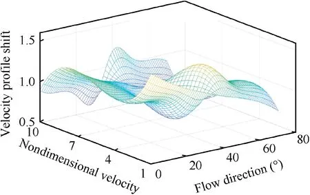
Fig.3 Wall function Fw.


2.5.Numerical validation
Lattice Boltzmann method considering rarefaction is used for the microscopic simulation in the near-wall region,which is the basis of data for training surrogate model.Therefore,it is necessary to check the accuracy of LBM-based platform.In this section,we simulate the flow of smooth surface microchannels under the rarefaction to verify the accuracy of the microscopic numerical simulation by comparing it with the unified model of microchannel flow proposed by Karniadakis et al.,which is applicable to a wide range of flow regions from continuous to transition media.The model agrees well with the results of Direct Simulation of Monte Carlo(DSMC),and therefore,it is reliable to compare the numerical results with the theory proposed by Karniadakis et al.
As shown from the results of DSMC and linearized Boltzmann equation,the velocity profile remains approximately parabolic within a wide range of Knudsen number.On this basis,the unified model of non-dimensional horizontal velocity profile can be expressed as

whereis a function ofand,andindicates the height of microchannel.According to Ref.25,=-1 corresponds to the second-order boundary condition in the slippery regime,which is selected for the model with a second order accuracy of the velocity distribution for a wide range of.
As shown in Fig.4,both the LBM model with rarefaction and the LBM model without rarefaction agree well with the analytical solution when=0.015.However,when=0.55,where rarefaction of flow should be considered,the LBM model without rarefaction has an obvious error compared with the analytical solution,which shows that rarefaction plays a more essential role asincreases.At the same time,LBM model with rarefaction still agrees well with the analytical solution,which shows that the model is applicable to micro/nano flows considering rarefaction in the near-wall region for the subsequent study.
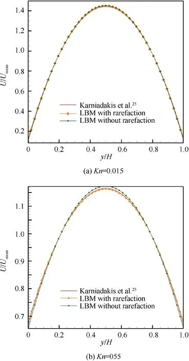
Fig.4 Comparison between LBM with rarefaction and LBM without rarefaction.
After the microscopic simulation in the near-wall region has been verified,the macroscopic simulation of the airfoil with grooved surface structure by using a boundary surrogate model needs to be validated.NACA0012 with the length of chord 20 cm and the length of the transverse groove region approximately 8 cmis selected for validation.The transverse triangle groove structure is arranged in the middle of the airfoil.The angle of the groove is 53.14°.The distance between grooves d is equal to the height of each groove h and the width of each groove.A fully developed turbulence flows through the upper surface of the airfoil with the inlet velocity 40 m/s.In this section,four transverse groove structures with=100 μm,=200 μm,=500 μm and=1000 μm are selected for comparison with the results of Wu et al.The flow solver is ANSYS Fluent,where the transition SST (Shear Stress Transport) model is picked as the turbulence transition model for its fitness to simulate the transition from laminar to turbulent.Therefore,transition SST model is suitable to study the flow control by the micro/nano grooved surface structure.Velocity boundaries derived from the surrogate model of groove as boundary conditions are applied on the smooth surface.
The total drag coefficient,pressure drag coefficient and viscous drag coefficient versus groove size are compared in Fig.5,which shows a good agreement between the results with present boundary surrogate model and those of Wu et al.It is worth mentioning that the grid number of the airfoil with groove size of 100 μm,200 μm,500 μm and 1000 μm in the simulation of Wu et al.are 500,000,570,000,530,000 and 550,000,respectively.However,in our simulation,since the surface structure is replaced by a boundary surrogate model,the total grid number for macroscopic simulation is only 43000.It is evident that our model greatly improves the computational efficiency with maintaining accurate results,especially for micro/nano grooved surface structure in smaller scale studied subsequently.
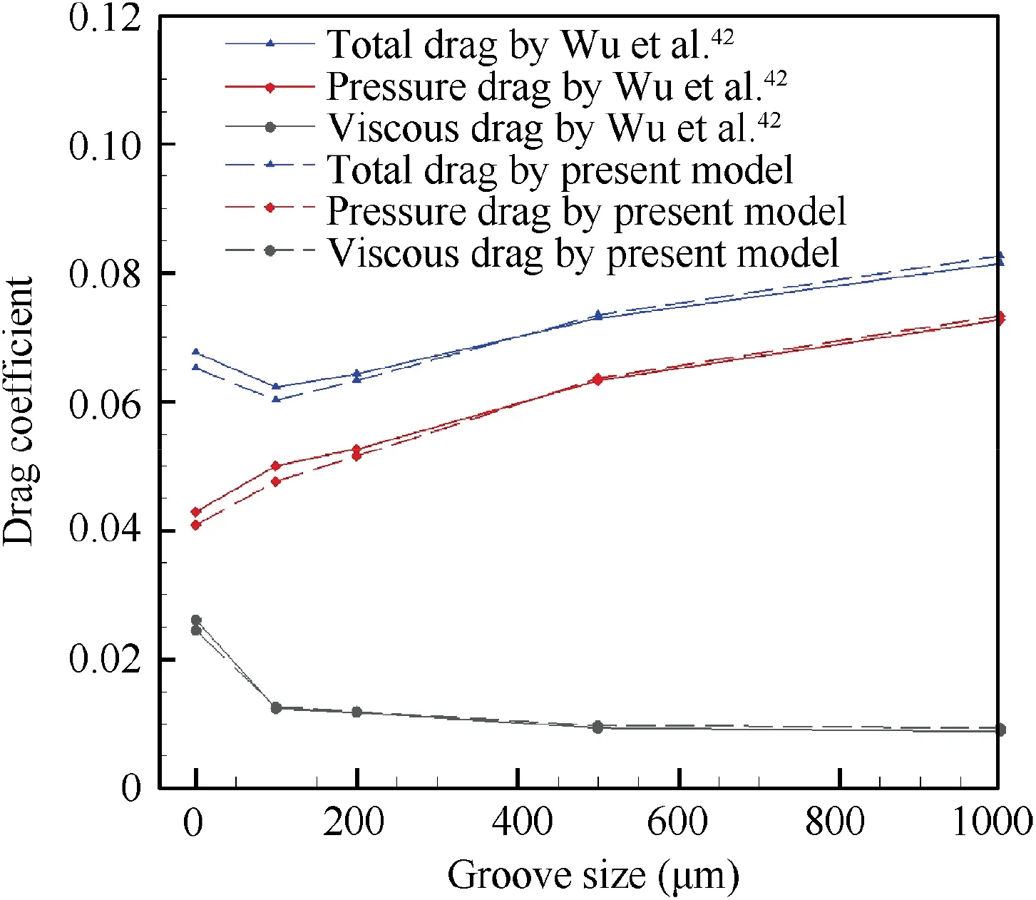
Fig.5 Comparison of drag coefficient for different groove ize.
3.Results and discussion
The proposed model has been applied to the assessment of the performance of the airfoil covered with micro/nano groove structure in the whole surface.An in-house airfoil ‘‘NLF 2#”has been chosen for the simulations,which is an improved airfoil with natural laminar flow design.The chord length of the airfoil is 0.2 m.The airfoils with smooth surface and micro/-nano grooved surface are shown in Fig.6.The non-slip boundary conditions are applied on the smooth surface and velocity boundaries derived from the surrogate model of groove as boundary conditions are applied on the groove surface.Neumann boundary conditions are on the pressure of farfield(99,614 Pa).The air is treated as ideal gas with temperature at 310 K at farfield boundary.The turbulence intensity is less than 0.2% and turbulent viscosity ratio is 10%.
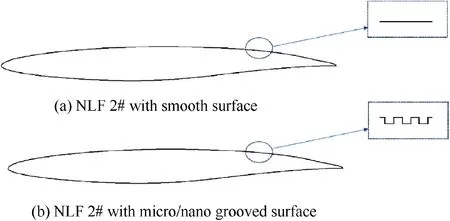
Fig.6 Geometric models.


Table 1 Grid independence study on aerodynamic parameters.
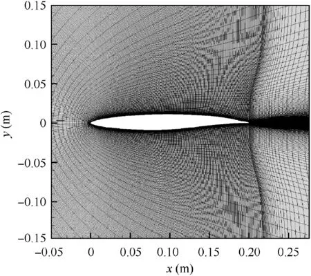
Fig.7 Illustration of mesh topology.
3.1.Laminar transition position
In our previous work,a wind tunnel experiment was conducted to test the aerodynamic performance of‘‘NLF2#”with smooth airfoil.The convective heat transfer coefficients of laminar flow and turbulence are exploited to detect the transition using an infrared camera.The experiment results are used to compare with the numerical results,verifying the correction of CFD solvers.In the simulation,distribution of intermittency above the airfoil surface by 5×10m(approximately 10 grids away from the wall) is selected in this paper to judge the laminar length over the airfoil.Fig.8 shows the results of intermittency at=0.6 and=0.7.The transition position of smooth airfoil in experiment and that in simulation are in good agreement,which shows that the results by CFD solvers can be obtained with confidence.The transition position of smooth airfoil is about 67.94% of the chord length at=0.6and about 65.12% of the chord length at=0.7 in simulation.The transition position of grooved airfoil is about 69.01% of the chord length at=0.6 and about 66.34% of the chord length at=0.7 in simulation.The results show that the transition position of grooved airfoil has a degree of backward at both Mach number.Therefore,we can conclude that the micro/-nano groove structure has the effect of delaying transition from laminar flow to turbulence and increasing the laminar length for flow control.As shown in Fig.9,the pressure coefficient Cdistribution of the smooth airfoil in simulation is almost consistent with the results in wind tunnel experiment.Moreover,the groove structure influences the expansion peak at leading edge and pressure recovery at trailing edge,resulting in form drag reduction.At=0.7,the intensity of shock reduced and the position moved backwards.
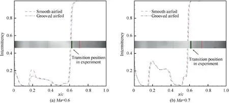
Fig.8 Comparison of laminar transition position.
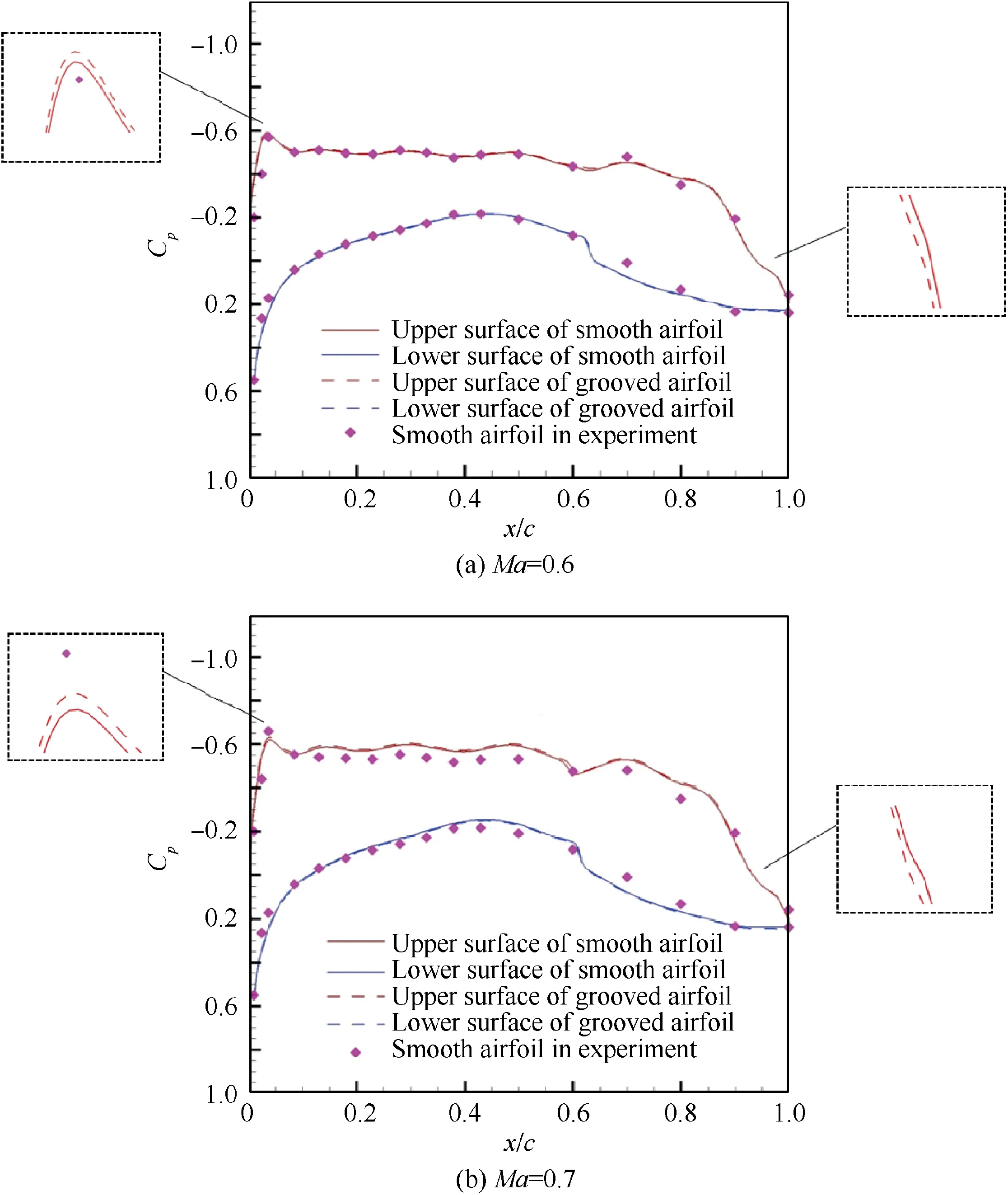
Fig.9 Comparison of pressure coefficient distribution.
3.2.Skin friction
As shown in Fig.10,the skin friction reduction by micro/nano groove structure in the surface is clearly visible at each Mach number.In the laminar flow region,there is little difference in Cbetween the smooth airfoil and grooved airfoil.However,in the turbulence region,the skin friction decreases significantly.As a result,the surface with groove structure has a stronger drag reduction effect on turbulence.
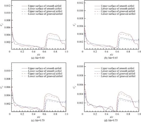
Fig.10 Comparison of skin friction coefficient.
3.3.Lift and drag
Fig.11 shows the comparison of lift coefficient and drag coefficient between smooth airfoil and grooved airfoil.When the micro/nano groove structure is applied in the surface,lift coefficient increases and drag coefficient decreases at the same Mach number as=0.6-0.75.As shown in Table 2,the variation in lift coefficient ΔCreaches maximum value(2.86%) at=0.75 and the variation in drag coefficient ΔCreaches maximum value(-5.96%)at=0.65.In addition,the lift-to-drag ratio of grooved airfoil significantly improves compared with smooth airfoil,the greatest variation of which reaches 8.67% at=0.65.According to the results,the improvements in aerodynamic efficiency of the grooved airfoil,compared to the smooth airfoil,are more evident at Mach numbers over 0.6 where the compressibility effects are significant.When the Mach number is greater than 0.6,the difference between the pressure integral of lower and upper surfaces of the grooved airfoil is greater compared to the smooth airfoil,leading to a more significant relative increase in lift coefficient and thus a more significant relative increase in lift-to-drag ratio.

Table 2 Comparison of lift-to-drag ratio between smooth airfoil and grooved airfoil.
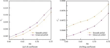
Fig.11 Comparison of lift coefficient and drag coefficient.
3.4.Velocity profile
As shown in Fig.12,the non-dimensional velocity profiles of the upper surface of smooth airfoil and grooved airfoil at different positions are shown.The log law is virtually reproduced although a notable error exists in the inner part of the boundary layer.Based on Eq.(3),Δare noted in Fig.12.According to Ref.14,a positive shift corresponds to a drag reduction,whereas a negative shift corresponds to a drag increase.Therefore,the effect of drag reduction exists at the three positions in the grooved airfoil surface.Remarkably,Δis different in three positions.This is because the local Reynolds number and the flow direction relative to the groove at different positions of the airfoil are different,which cannot be ignored.To the best of the authors’ knowledge,this issue has not been taken into account in the existing riblet models,which illustrates the significance of our boundary surrogate model.
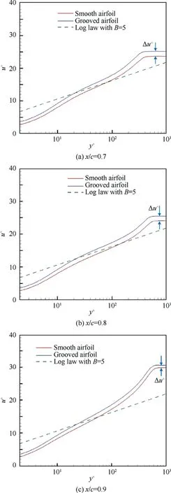
Fig.12 Comparison of non-dimensional velocity profile at different positions.
3.5.Turbulence intensity and turbulence kinetic energy
Normally,the turbulent intensity is defined as the ratio of the mean velocity to the pulse velocity.Fig.13 shows that the maximum turbulent intensity on the grooved airfoil surface is 0.97%,which is lower than that on the smooth airfoil surface(1.12%).The reducing rate reaches to 13.39%.The groove structure in the surface weakens the turbulence intensity,which is helpful for the drag reduction.The turbulence effect was validated by Ref..
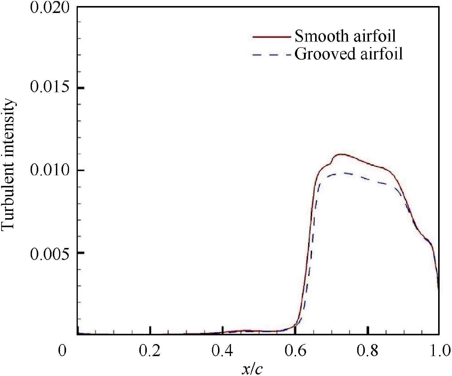
Fig.13 Comparison of turbulence intensity.
The turbulent kinetic energy is one of the main parameters reflecting the intensity of turbulent pulsations,which of the near-wall flow field is analyzed to explain the drag reduction effect of the groove structure.As shown in Fig.14,the maximum turbulent kinetic energy of the turbulence boundary layer significantly reduced at the same position on the grooved airfoil surface and smooth airfoil surface,indicating that the turbulent pulse in the boundary layer weakens,causing the additional friction to decrease.This interesting phenomenon implies the near-wall flow field of the grooved airfoil is more stable than that of the smooth airfoil.In other words,there is less momentum exchange and flow loss relatively compared to the smooth airfoil.
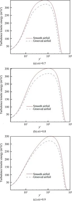
Fig.14 Comparison of turbulence kinetic energy at different positions.
According to the reference,the physical mechanism of this phenomenon may be that groove structure immersed in the boundary layer induces the secondary vortex and reduces the skin friction by suppressing the generation of large-scale vortex structure,thus reducing the energy and momentum loss inside the boundary layer.Choiindicated that groove structure shifted the velocity profile upwards causing an increase in viscous sublayer thickness,which resulted in the reduction of turbulence intensity in the near-wall region.Subsequently,the study of the physical mechanism of this phenomenon will be our focus.
4.Conclusions
In this paper,the boundary surrogate model is proposed to simulate multi-scale global flow field of the airfoil covered with micro/nano grooved surface structure.The microscopic nearwall region is replaced by boundary surrogate model of micro/nano grooved surface structure based on the microscopic simulation data,and the global flow field is solved with modified wall boundary condition based on surrogate model.Using this innovative simulation method,the turbulence control of micro/nano groove structure in the airfoil surface is investigated,and considerable computing resources are saved in the process.
Compared with the existing models,the upward shifts of velocity profile in the logarithmic and wake regions along the chord length are reproduced by adopting a wall function as boundary conditions on the surface of smooth airfoil in our improved model.The feasibility of this model is verified by carrying out the simulation of NACA0012 airfoil with grooved surface structure.
Subsequently,we analyze the turbulence flow control of micro/nano grooved surface structure.The aerodynamic performance of the grooved airfoil is compared with that of the smooth airfoil.According to the results in Section 3,we conclude that the micro/nano groove structure has the effect of delaying transition from laminar flow to turbulence and increasing the laminar length for flow control.Moreover,the lift-to-drag ratio of grooved airfoil significantly improves compared with smooth airfoil.In the turbulence region,the skin friction of grooved airfoil reduces significantly.The near-wall flow field of the grooved airfoil is more stable than that of the smooth airfoil.In other words,there is less momentum exchange and flow loss relatively compared to the smooth airfoil.
It should be noted that this simplified calculation can only be applied when the riblets are immersed in the viscous sublayer.In the future,we will develop more advanced surrogate models for micro/nano surface structure at various scales and perform in 3D framework for the design of aircraft.
The authors declare that they have no known competing financial interests or personal relationships that could have appeared to influence the work reported in this paper.
This research was funded by AECC Commercial Aircraft Engine in the project of Laminar Flow Design and Turbulent Drag Reduction of Compressor Blade Profile and Experimental Verification.
 Chinese Journal of Aeronautics2022年2期
- Chinese Journal of Aeronautics的其它文章
- Pressure-induced instability and its coupled aeroelasticity of inflated pillow
- Adjoint boundary sensitivity method to assess the effect of nonuniform boundary conditions
- Transit time difference and equal or non-equal transit time theory for airfoils with lift
- Nonlinear uncertainty quantification of the impact of geometric variability on compressor performance using an adjoint method
- High precision and efficiency robotic milling of complex parts:Challenges,approaches and trends
- Review on anti-loosening methods for threaded fasteners
