Effect of cooling strategies on performance and mechanism of helical milling of CFRP/Ti-6Al-4 V stacks
Jiying GE ,Gung CHEN,b,* ,Yongxing SU ,Yunhe ZOU ,Chengzu REN,b ,Xud QIN,b ,Guofeng WANG,b
a Key Laboratory of Mechanism Theory and Equipment Design of Ministry of Education,Tianjin University,Tianjin 300354,China
b Tianjin Key Laboratory of Equipment Design and Manufacturing Technology,Tianjin University,Tianjin 300354,China
KEYWORDS CFRP/Ti-6Al-4V stacks;Cryogenic cooling;Cutting temperature;Helical milling;MQL
Abstract Hole-making for Carbon Fiber Reinforced Plastics (CFRP)/Ti-6Al-4 V stacks is crucial for the assembling strength of aircraft structure parts.This work carried out experimental work for helical milling (HM) of the stacks with sustainable cooling/lubrication (dry,MQL and cryogenic)conditions.Cutting forces and temperatures at the CFRP layer,Ti-6Al-4 V layer and the interface of stacks were obtained by a developed measuring system.The temperatures in CFRP machining at cryogenic condition varied from-167°C to-94°C,which were much lower than those at dry and MQL conditions.The maximum temperature near the interface of stacks for the ninth hole was higher than 240°C due to heat conduction from Ti-6Al-4 V layer.The hole quality,hole diameter and tool wear mechanism at different cooling/lubrication conditions were presented and discussed.MQL condition generated mainly extrusion fracture for the fibers,due to the reduced friction effect compared with dry condition.MQL was helpful to reduce the feed mark at the hole surface of Ti-6Al-4 V alloy.The flank wear of cutting edge at MQL condition was better than those at dry and cryogenic conditions.Cryogenic cooling contributed to better CFRP surface with smaller delamination and hole entrance damage due to the increased resin strength and fiber brittleness.The damage near the entrance of CFRP were analyzed by the contact state of cutting edges and fibers.Additionally,hole diameters near the exit of CFPR layer were larger than other test positions.This work provided feasible processes for improving hole quality and tool life in hole-making of CFRP/Ti-6Al-4 V stacks.
1.Introduction
The stacks of carbon fiber reinforced plastics (CFRP) and Ti-6Al-4 V have been extensively utilized in aerospace industry,owing to the excellent performance such as corrosion resistance,high strength and light weight.To achieve high geometrical accuracy of assembling holes of the stacks,CFRP and Ti-6Al-4 V alloy should be machined together instead of being machined separately.Due to the different mechanical behaviors of the materials,hole-making for the stacks is a challenging task.Considerable research efforts have been devoted to explaining the mechanism of hole making for stacks and improving the quality of hole processing.
Conventional drilling (CD) and helical milling (HM) are two main processing methods applied for hole making of stacks.Many works so far have been focused on CD of stacks,including CFRP damage,hole quality evaluation and tool wear mechanisms.Machined hole quality including the geometrical accuracy,surface or subsurface damage is highly related to the variation of cutting forces and temperature.The magnitude of thrust force and torque can be affected by tool material,cutting speed,feed rate and tool wear.
The damage at the entrance and exit of machined holes is mainly concerned in hole-making of stacks.One of the major serious damage in CFRP hole-making is delamination which may be generated when the thrust force exceeds a critical value.In order to predict the critical thrust force,Qi et al.established a mechanical model for drilling of metal-FRP stacks.Delamination factor is normally utilized to characterize the degree of delamination.There are usually two different ways to evaluate the delamination factor:conventional delamination factor()which is defined in terms of the diameter of the delamination zone,and regional delamination factor ()which is defined according to the delaminated area.Normally,delamination factor increases with the increasing feed rate and tool wear.On the other hand,burrs at the entrance and exit of machined holes are the main defects in metal layers.It was reported that burrs at the exit of machined holes are more serious than those at the entrance,and the height of burrs increases with increasing thrust force and tool wear in drilling of CFRP/Titanium stacks.
Due to the different material behaviors of the stacks,the chip formation mechanism and damage form are different for drilling of CFRP and metals.Fibers in CFRP are removed by the way of brittle fracture which normally generates powdery chips during hole-making.However,continuous chips of Ti-6Al-4 V are mainly formed by elastoplastic deformation.Different machinability at the interface of stacks can lead to variation of stresses and cutting temperature,which will reduce the cutting stability and increase tool wear.Owing to the different mechanical properties,such as elastic modulus and tensile strength,the deformation of the layers is different in drilling process,which can cause interlayer gap and noncoaxiality.Meanwhile,due to the exist of interlayer gap which gives growing space for burrs,chip may enter into the gap and causes damage at the interface of the stacks.Normally,there are three sources of non-coaxiality,that is,pure bending,horizontal displacements and local deformation.Besides,mechanical damage can be observed at the CFRP hole exit,owing to the invading of Ti-6Al-4 V entry burrs.Additionally,defects occurred at hole wall are also well concerned,especially for CFRP layer.Most of the damages on CFRP holes are related to the fiber cutting angle which was defined as the angle between the cutting edge and fiber orientation.Defects like uncut carbon fibers,fibers pull out and delamination are generated at different fiber cutting angles.In addition,scratch marks can be observed on CFRP hole wall,due to Ti-6Al-4 V chips,build up edge or drilling withdrawing.The machined surface of Ti-6Al-4 V alloy normally exhibits less damage than that of CFRP composite,and the main defects of machined hole surfaces were reported as chips adhering and feed marks.
Tool wear is more serious in stacks drilling than that involved in single layer drilling.Park et al.found that the flank wear of PCD tool with high spindle speed is more serious than that with lower spindle speed in drilling of CFRP-Ti stacks,because of the higher drilling temperature.Montoya et al.applied coated and uncoated tungsten carbide tools in drilling of CFRP/aluminum stacks,and it was reported that abrasion was the main wear mechanism which affected the whole cutting edges.Tool wear mechanism was also investigated when machining of separated materials.It was stated that abrasive wear is predominant when machining of CFRP due to the hard and brittle carbon fibers.While,tool wear in drilling of single Ti-6Al-4 V layer is dominated by edge chipping and adhesion wear.On the other side,it was reported that the Ti-6Al-4 V chips adhered to cutting edges can be brushed away in the process of CFRP drilling,which may be helpful to eliminate the edge chipping and increase the tool life.
Helical milling (HM) is a relatively new process for hole making.Compared with CD,there is more space to remove chips and dissipate cutting heat in HM,since the diameter of cutting tool is smaller than that of machined holes.In HM,material removal generated by the bottom cutting edges can be considered as a continuous cutting process,while the cutting process of peripheral cutting edges can be considered as a discontinuous cutting due to the relative movement between the cutting edges and workpiece.Many researches were carried out to investigate the cutting forces and the influence of tangential feed and axial feed on the cutting forces in HM of CFRP/Titanium stacks.Compared to the central loading position of axial force in CD,the axial force in HM is loaded eccentrically.It was reported that the thrust forces in HM are proportional to the feed rates,but inversely proportional to the spindle speeds.On the other hand,Rahim et al.applied embedded thermal couple to measure the cutting temperature in HM of CFRP/Aluminum stacks under dry condition.It was presented that the cutting temperature increased with the increasing cutting speed.Tool wear is another important problem in HM of stacks.Wang et al.compared the tool wear in HM of single layer and CFRP/Ti stacks.Results indicated that breakage and adhesive wear often generated in Ti-6Al-4 V layer.While,abrasive wear was the main wear mechanism in CFRP layer.Tool wear in HM of stacks is the combination of two wear mechanism mentioned above,which can affect the cutting performance of the stacks.
Cutting temperature is a key factor which has a great influence on hole quality and tool wear in hole-making processes.Normally,the stack sequences,cutting speeds,feed rates,cooling condition and the drilling tool geometry affect the drilling temperature of CFRP and metals during drilling the CFRP/alloy stacks.The variation of temperature affects the thermal-mechanical behaviors which may cause thermal damage during stacks machining.For instance,thermal damage ring on CFRP hole exit was observed by several researches.Additionally,resin degradation and debonding were observed in CFRP layer when the cutting temperature exceeded the glass-transition temperature.Therefore,temperature control is meaningful for hole-making of stacks.
Recent developments of cooling and lubrication methods which can change thermal-mechanical behaviors in machining have attracted much attention.Minimum quantity lubrication(MQL)and cryogenic machining are considered as sustainable cooling/lubrication strategies,since they can save lubricant costs and protect environment.MQL can change the thermal-mechanical behaviors by reducing the friction coefficient between tool and workpiece,and it is beneficial to reducing the cutting temperature in machining.The temperature is normally lower than -180°C under cryogenic conditions,so the Young modulus and tensile strength will be increased,which will significantly affect the deformation behaviors.
As a sustainable process,MQL was widely applied in drilling or milling of alloys.It was reported that cutting forces and temperature were greatly reduced.Surface integrity,including surface defect,sub-surface deformation layer,microhardness value,and surface roughness was also improved.Qin et al.reported that tool wear and surface roughness were significantly improved in HM of Ti-6Al-4 V at MQL condition.Duan et al.investigated the effects of air flow field and nozzle angle on the improvement of surface roughness in milling of 7050 aluminum alloy with nanofluid MQL condition.Wang et al.investigated the influence of MQL coolant delivery position on the secondary cutting edges in drilling of CFRP.The surface roughness and exit defects were improved with MQL condition.Iskandar et al.presented that high air flow rate coupled with low oil flow rate is helpful to increase the tool life in machining of CFRP.MQL was also applied in drilling of CFRP/metal stacks.Meshreki et al.investigated CFRP/aluminum stacks drilling under different cooling conditions.Compared with dry condition,most of the hole quality characteristics are better in MQL drilling which generated the same quality as flood coolant,especially for high pressure with low flow rate.Similarly,the surface morphology of CFRP layer was improved and the tool wear was alleviated at MQL condition in drilling of CFRP/Ti-6Al-4 V stacks.However,it was reported that MQL was failed to reduce the thrust force,cylindricity error and delamination extent.Above all,MQL exhibited both positive and negative influence on the drilling of stacks.
Cryogenic machining,as a sustainable machining process,is widely used in drilling of single CFRP and titanium alloy.Cryogenic drilling can alleviate the tool wear and improve the surface integrity of hole wall in CFRP drilling,however,the delamination factor was normally increased due to higher thrust force in cryogenic drilling process.Park et al.applied a cryogenic and ultrasonic vibration hybrid method for the deburring of CFPR.Results indicated a high efficiency in removing burrs at hole exit.In addition,Joshi et al.proposed a delamination prediction model for both dry and cryogenic drilling.The effect of remarkable decreasing temperature in titanium alloy cryogenic drilling increased the hardness of the material.Additionally,the thrust force was increased and the chip morphology of uniform segmentation became better.Although cryogenic cooling appeared with some advantages in drilling of CFRP or metals,there are few studies about cryogenic machining of CFRP/metal stacks.Impero et al.reported that the thrust force,torque and hole diameter error can be reduced in cryogenic drilling of CFRP/Ti stacks,however,the burr height was higher than that at wet condition.
Although different hole-making strategies have been carried out for stacks.Many problems still exist such as the hole quality,including the poor hole surface roughness,inferior uniformity of hole size and tool wear.There are few studies concerning about the effect of cooling/lubrication conditions on the hole quality in HM of stacks.This work focuses on the effect of dry,MQL and cryogenic machining on helical milling of CFRP/Ti-6Al-4 V stacks.The cutting forces,temperatures,the hole quality as well as the tool wear during the helical milling of stacks with different cooling/lubrication conditions will be presented.
2.Material and methods
2.1.Materials and cutting tool
A kind of multi-orientation CFRP plate with fiber stack sequence of [45 °/0 °/-45°/90°/0°/0°/90°/-45°/0°/45°]and commercial grade Ti-6Al-4 V alloy plate were applied in HM experiments.The stack sequence in the experiments was CFRP on the top and Ti-6Al-4 V on the bottom.The stacked plates with thicknesses of 5.4 mm (CFRP) and 5 mm (Ti-6Al-4 V)were clamped together and machined to the size of 250 mm×121.5 mm before hole-making experiments.Fourflute ultrafine grained cemented carbides(WC-12%Co)milling tools were used for the helical milling experiments.The detailed tool geometries are listed in Table 1.
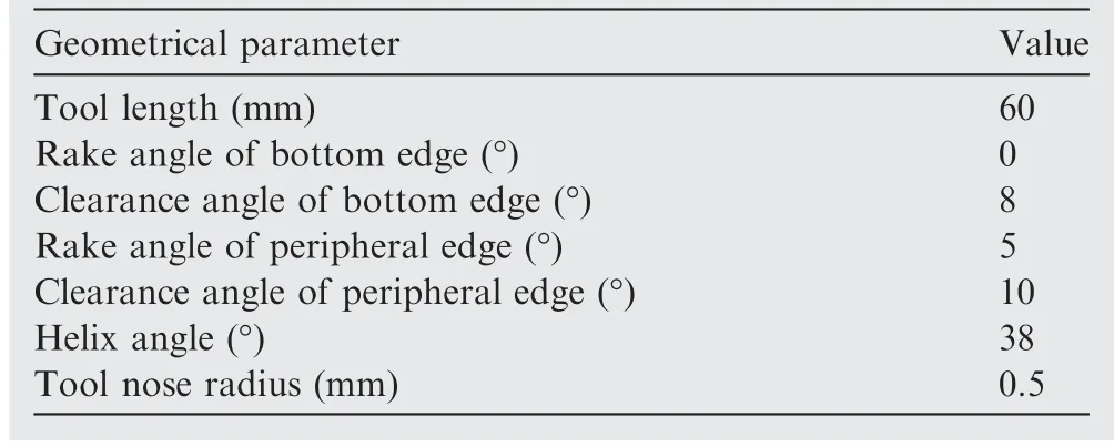
Table 1 Tool geometries.

Table 2 Cutting parameters for different cooling/lubrication conditions.
2.2.Experimental condition
In this work,helical milling experiments of CFRP/Ti-6Al-4 V stacks with three cooling and lubrication conditions (Dry,MQL,Cryogenic cooling) were carried out with cutting parameters as listed in Table 2.New tool was applied in each cooling/lubrication condition.The tool was cooled when each hole was machined to ensure that the initial temperature of tool was identical before machining.For each cooling/lubrication condition,each tool was supposed to machine twelve holes,however,the process will be terminated when the wear of the bottom cutting edge is larger than 150 μm for all conditions or the cutting temperature exceeds the ignition point(approximately 300°C)of the lubrication at the MQL conditions.Additionally,the average flank wear of the cutting edge was measured when each two holes were machined by an optical microscope during the experiments.

Table 3 EDS results of mass fraction (wt%) at positions of P1-P7.
2.3.Experimental system and procedures
The experimental system is shown in Fig.1.HM experiments were performed on a 5-axis machine center (DMU 60 mono BLOCK).Liquid nitrogen (LN) supplied by a YDZ-100 self-pressurized liquid nitrogen tank was used in cryogenic condition.The pressure of the LNsupply system was set about 0.1 MPa.The pressure of the MQL device (KS-2106)with two nozzles was set as 0.45 MPa,and the flow speed of lubrication oil was 20 mL/h.The special lubricating oil was composed of synthetic lubricating oil with anti-wear agent,stabilizer and anti-rust agent.To prevent the CFRP chips from being blown into the air when the cooling/lubrication conditions were applied,a cover and an industrial vacuum cleaner were developed to collect the chips.The nozzles of MQL and LNwere mounted on the cover,pointing to the machining area.Meanwhile,the cover was moved to specific condition to ensure that the LNand MQL were sprayed to identical relative position between the nozzle and the hole to be machined.
The workpieces were fixed on a fixture which was installed on the top of a Kistler® 9257A three-component dynamometer,as illustrated in Fig.1.The forces were measured by a Kistler® 5070A charge amplifier and an NI® USB-6216 A/D converter.K-type thermocouples produced by OMEGA®were used to measure the temperatures in HM at dry and MQL conditions,while T-type thermocouples were applied for cryogenic condition.The thermocouples were mounted in the micro-holes with diameter of 1.2 mm by heat-conducting glue,and the positions of thermocouples are shown in Fig.2.Cutting temperatures at three positions were measured when each four holes were machined (Tested hole numbers:No.1,No.5 and No.9).Considering the heat accumulation during HM,the cutting temperatures at the positions near the exit of CFRP layer (T1) and Ti-6Al-4 V layer (T3) were measured.Meanwhile,to investigate the effect of cutting temperature on the stack interface,the temperature at the interface(T2) was also measured by a thermocouple mounted on the entrance of Ti-6Al-4 V layer.The distance of the measuring point and the machined hole surface was 0.5 mm.The bottom of the thermocouple installing holes was machined flat to ensure the consistency of the measuring positions.
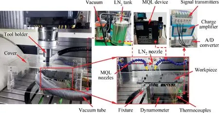
Fig.1 Experimental system with cooling/lubrication systems of MQL and LN2.
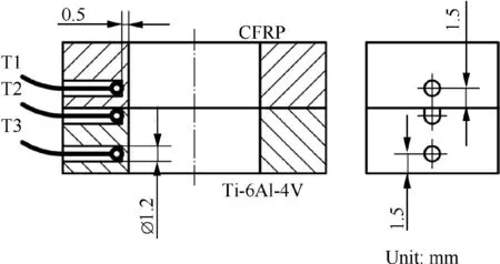
Fig.2 Schematic of positions of installed thermocouples T1,T2 and T3.
In this work,the low magnification surface morphologies of Ti-6Al-4 V holes,and the hole edge morphologies of CFRP were observed by a Keyence® VHX-1000 digital microscope.The high magnification surface morphologies of CFRP and Ti-6Al-4 V were observed by a JSM-7800F Scanning Electron Microscope (SEM).The delamination damage of CFRP holes was measured by a USIP 40C-scan acoustic microscope.Besides,the metallographic microstructures were observed by ZEISS® Axio Scope A1 microscopy.The hole diameters at different conditions were measured by a Daisy® 8106-HA Coordinate Measuring Machine.
3.Results and discussion
3.1.Cutting temperature and forces
Measured axial forces and the temperatures measured by thermocouples T1,T2 and T3 at the dry,MQL and cryogenic conditions are presented in Fig.3(a),(b) and (c),respectively.Cutting temperatures of T1-T3 increased gradually from approximately 22°C to 40°C when the tool machined CFRP layer under dry and MQL condition.However,the temperature of T1 decreased from approximately -120°C to-170°C due to the accumulated cooling effect,when CFRP layer was machined under cryogenic condition.As shown in Fig.3(a),when the tool machined CFRP layer at dry condition,temperature of thermocouple T1 reached a peak value when the tool reached the measuring position in CFRP layer.Additionally,the cutting temperatures rose rapidly when Ti-6Al-4 V layer was machined,and all temperatures of T1-T3 reached the maximum values at the end of cutting.That is caused by the heat conduction due to the high temperature generated in HM of Titanium alloy.The maximum temperature of thermocouple T3 at the dry condition was higher(about 178°C) than those of T1 and T2 for hole No.1.
As shown in Fig.3(a)-3(c),the axial force increased slowly at CFRP layer of No.1 hole,while it became more stable in the subsequent holes,such as the force of hole No.5 in Fig.3(d).The slightly force rise should be caused by the increase of initial tool wear.The axial force climbed suddenly at the interface of the stacks.After that,a slightly decrease can be seen in Ti-6Al-4 V layer due to temperature rise,which can decrease the shear and compressive stress at high strain rate conditions.Besides,as shown in Fig.3(d),the typical horizontal forces fluctuated near zero due to the periodically material removal,and the amplitude increased for Ti-6Al-4 V alloy due to higher forces.
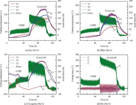
Fig.3 Measured forces and cutting temperature of the first (No.1) and fifth (No.5) machined holes in different cooling/lubrication conditions.
To study the influence of cooling/lubrication conditions and tool wear on the cutting temperature in HM,the instantaneous temperature of thermocouples when the bottom cutting edges reached the axial positions (T1,T2and T3as indicated in Fig.4) for different hole numbers are shown in Fig.4.Furthermore,the maximum interfacial temperature(T2) was also obtained to study the effect of the heat conduction during machining of Ti-6Al-4 V on the interface of stacks.With the increase of hole number,most of the temperatures increase,except for the temperatures of CFRP outlet(T1)and the interface of stacks(T2)at cryogenic condition.The temperature of T1and T2for Holes No.1,No.5 and No.9 are less than 53°C at the dry and MQL conditions.While the corresponding temperatures at cryogenic condition vary from -167°C to -94°C.Additionally,the temperatures of T3indicates the instantaneous temperatures near Ti-6Al-4 V outlet.Besides,the temperatures (T1,T2and T3) at MQL condition are little lower than those at dry condition.While,the temperatures at cryogenic condition are much lower than those at dry and MQL conditions,indicating a significant cooling effect.
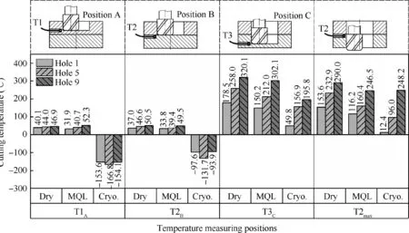
Fig.4 Instantaneous cutting temperature and maximum interface temperature under different cooling/lubrication conditions.
Note that the maximum interface temperatures of No.9 hole for all conditions were higher than 240°C,which were higher than the glass transition temperature (180°C approximately) of CFRP.Therefore,it can be concluded that the instantaneous cutting temperature of interface of stack (T2)is less than 50°C when the tool just machined the interface position.While,due to heat conduction,the maximum temperature near the stacks (T2) for No.9 is higher than 240°C.While,for most cooling/lubrication conditions for No.1 and No.5,the maximum temperature near the interface is lower than 160°C.Over all,the in-situ cutting load (thermal-mechanical load)temperature for CFRP is much lower than glass transition temperature,however,the post heat conduction temperature may exceed the value with the increase of tool wear.
In HM,the mean resultant force()in the horizontal plane was calculated by the measured forces of Fand F.

The measured mean axial force()and the resultant force as well as the linear fitted values of cutting forces for different numbers of machined holes under different cooling/lubrication conditions are presented in Fig.5.
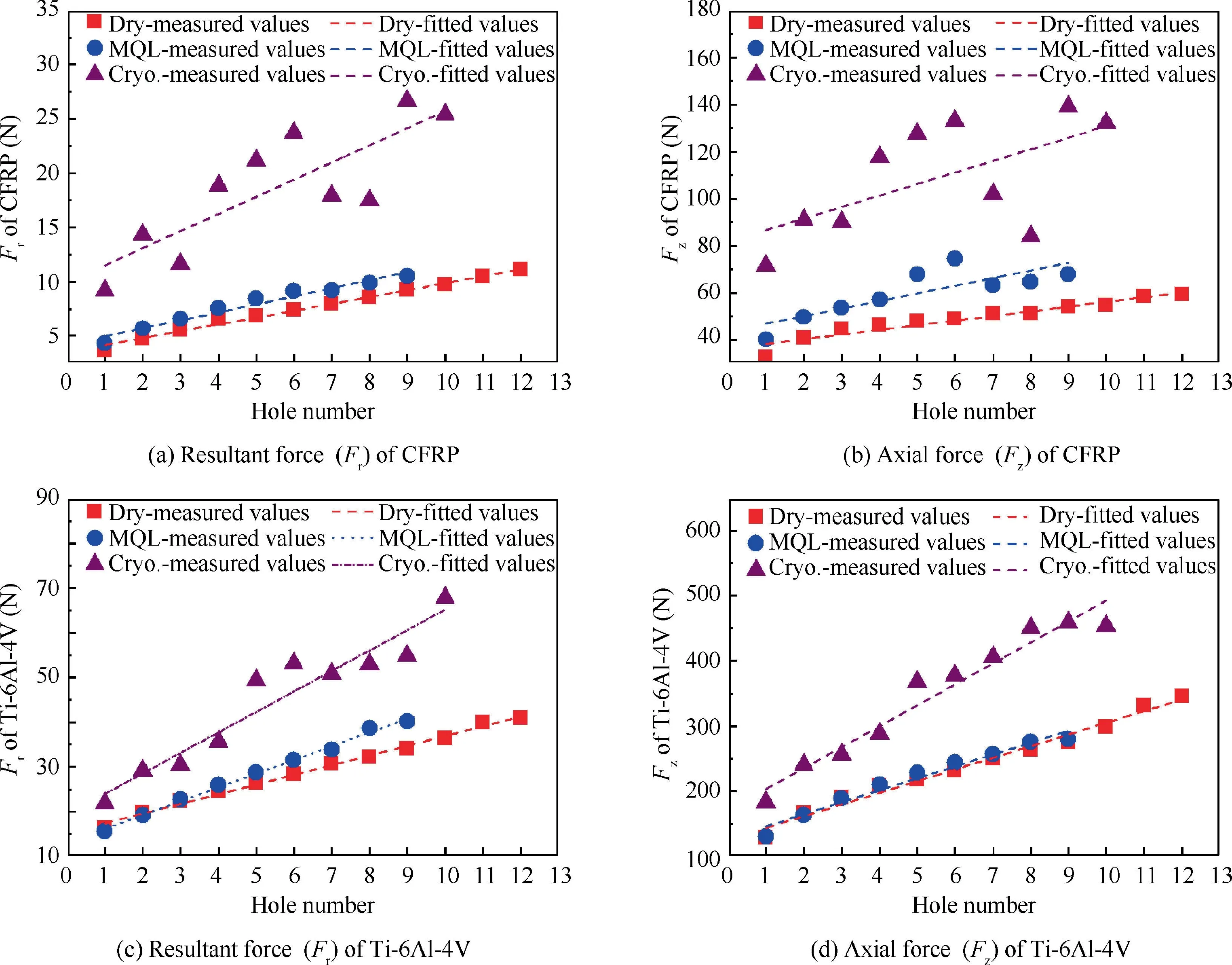
Fig.5 Cutting forces of different holes at different cooling/lubrication conditions.
Both of the resultant and axial forces at different conditions increase with the hole number almost linearly,due to the increase of tool wear.Note that the resultant forces in HM are much smaller than the axial forces.As most of the resultant forces are generated by the bottom cutting edges,the forces along the horizontal plane can be balanced with the four cutting edges due to identical material removal volume.
Additionally,the forces at cryogenic condition are much higher than those at dry and MQL conditions.This is consistent with the results of cryogenic drilling of single CFRP layer.For CFRP layer,the resultant forces in HM at cryogenic condition exhibit fluctuated increase from approximately 9 N to 27 N.While,the axial forces increase from approximately 77 N to 140 N with a fluctuation,which should be caused by the slight variation of LNinjection.As indicated in Fig.4,the machining temperatures of CFRP(T1)at cryogenic conditions are about -150°C,approximately 200°C lower than those at dry or MQL conditions.Low machining temperature in CFRP can lead to the matrix hardening and increase the cutting forces.Similarly,the machining temperatures of Ti-6Al-4 V layer at cryogenic conditions(T3)are also much lower than those at dry and MQL conditions.According to the high strain rate compression tests,the flow stress of Ti-6Al-4 V alloy is higher at lower temperature conditions,which will contribute to the increase of cutting force.
Additionally,both of the resultant and axial forces at MQL conditions are slightly higher than those at dry conditions.Note that the machining temperatures (T1in Fig.4) of the CFRP at MQL condition are just 8°C and 3°C lower than those at dry conditions for the holes of No.1 and No.5,respectively.Therefore,the cooling effect of MQL has little influence on the forces.However,MQL may generate moist powdery chips which will clog along the tool edges and increase the forces between the cutting edges and machined surface.For Ti-6Al-4 V layer,the resultant and axial forces of MQL condition are almost the same as those of dry HM in the first few holes,but gradually become larger than dry condition from the fourth hole.The machining temperatures of Ti-6Al-4 V (T3) at MQL condition are approximately 28°C and 46°C lower than those at dry condition for the hole of No.1 and No.5,respectively.The little temperature difference has hardly influence on the flow stress of Ti-6Al-4 V alloy.Similarly,it was reported that the magnitudes of cutting forces under MQL were closed to or larger than that under dry conditions in drilling of CFRP/Ti-6Al-4 V stacks.Additionally,the slightly higher cutting forces in Ti-6Al-4 V layer at MQL conditions should be mainly related to the increased friction effect caused by CFRP chips adhering to the tools.Over all,MQL is not beneficial for reducing cutting force in HM of CFRP/Ti-6Al-4 V stacks.
3.2.Hole quality
To analyze the mechanism of fiber removal,the SEM results of machined surfaces at dry,MQL and cryogenic conditions are shown in Fig.6.As indicated in the large magnification graphs(I,II and III),the fiber fractured surfaces at dry condition are more regular than those at MQL and cryogenic conditions.The fractured surfaces of fibers at MQL exhibit as scraped surfaces with few fractured segments.While,the fractured end of fibers at cryogenic condition appear as brittle characteristics with inclined fractured surface.
Fig.7 illustrated the schematics of the fiber bearing at different cooling/lubrication conditions.The resultant cutting force caused by the contact between peripheral edge and fibers can be recomposited as tensile force along the fiber direction and normal force perpendicular to the fiber direction.Thus,the fractured characteristics of fibers may exhibit tensile,shearing,stretching or extrusion according to the variation of force components.The fiber fracture surfaces at dry condition(Fig.6(a)) are almost perpendicular to the fiber axis,and the fracture positions are random,which is similar to the fracture in unidirectional CFRP tensile test.Thus,the fiber fracture at dry condition may be primarily caused by tensile stress.
Note that the machining temperature of MQL is close to that at dry condition,however,the friction between the cutting edge and fiber is reduced when MQL is applied,due to the lubrication effect.As indicated in Fig.7b,when the tensile force is reduced,fibers become difficult to be fractured by tensile force.Thus,normal force will be increased due to the increasing extrusion force with the movement of cutting edge.Therefore,larger normal force can cause pressure for the fibers which will lead to extrusion fracture.It can be noted that there are many fibers have step-like scraped fracture surface (Fig.6(b)),similar as extrusion fracture characteristic in orthogonal cutting of UD-CFRP laminates.
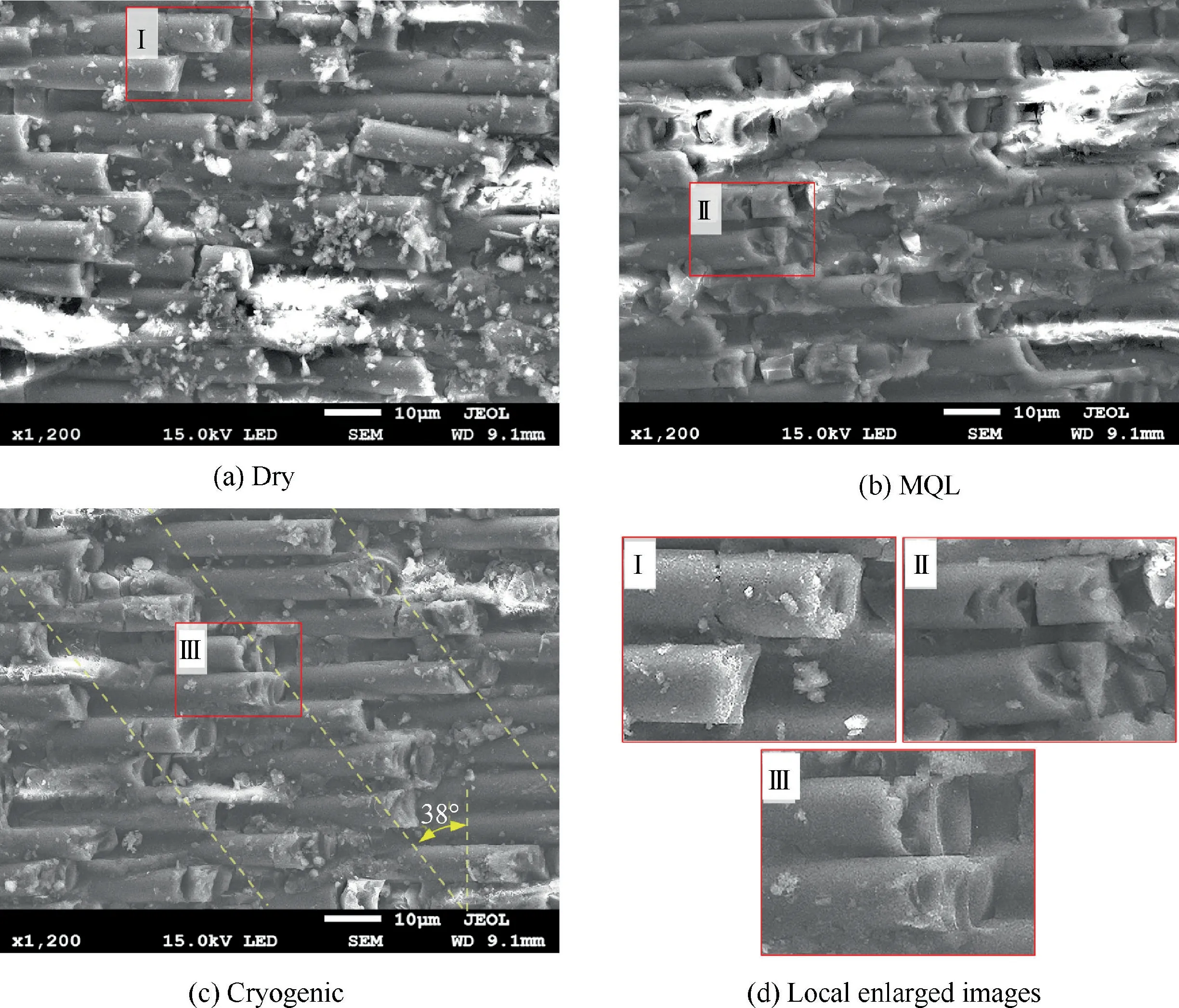
Fig.6 Hole morphologies and typical fiber fracture surfaces of No.5 CFRP holes under three cutting conditions.
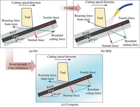
Fig.7 Schematic of forces analysis of single fiber at different cooling/lubrication conditions.
For cryogenic condition,the machining temperature (T1in Fig.4) was approximately -160°C.It was reported that the tensile strength of carbon fiber decreases at low temperatures,while the strength of epoxy increases.In addition,as indicated in Fig.6c,the inclined dash lines represent the contact positions of peripheral edges and hole surface since the helix angle is 38°.Note that the fibers fracture positions distribute near the dash lines,which indicates that most of fibers tend to fracture at the positions once they contact with the peripheral edges.Therefore,the fibers are more brittle to be cut and the fracture positions are more concentrated due to the enhanced strength of the matrix at cryogenic condition.Above all,the CFRP surface machined by HM under cryogenic condition is more regular and the combined strength between the machined fibers and matrix is better than other conditions,due to the enhanced matrix strength and fiber brittleness.
The surface morphologies of Ti-6Al-4 V holes are observed by digital microscope and shown in Fig.8.Obvious inclined feed marks can be observed at the dry condition.While,the hole surface under MQL and cryogenic condition are smoother than that at dry HM condition.Obvious feed marks exist at the upper part of hole surface at MQL condition.That should be related to the tiny CFRP chips adhering to the cutting edges,which may generate a polishing effect to the machined surface.Note that the polishing effect may be reduced at deeper hole surface due to the variation of MQL lubrication effect,and the reduction of powdered CFPR chips,since the chips of titanium alloy may take away the CFRP chips during the HM process.
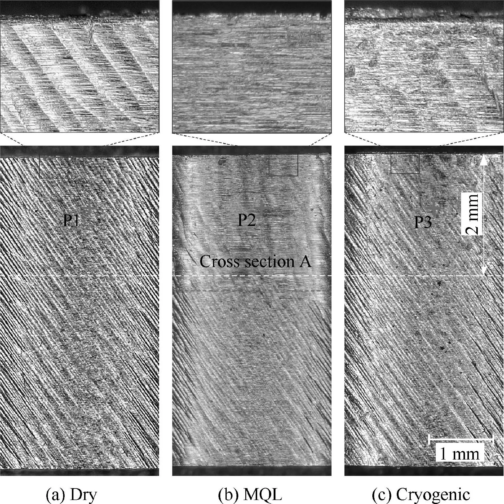
Fig.8 Surface morphologies of No.1 hole for Ti-6Al-4 V layer at different cooling/lubrication conditions.
The local morphologies of positions P1,P2 and P3 (in Fig.8) are observed by SEM and illustrated in Fig.9.It can be seen that the feed marks at dry and cryogenic conditions are obvious,while no obvious feed mark is observed at the MQL condition.In addition,small grooves can be observed at dry condition,and it should be related to the plastic deformation caused by the micro-geometrical texture along the peripheral cutting edges.For MQL and cryogenic conditions,the surfaces seem smoother,which should be related to the polishing effect caused by the adhering CFRP powders or the relatively lower temperature at cryogenic condition.
To further check the microstructure of machined hole surfaces,Ti-6Al-4 V plate was cut along cross-section A (in Fig.8),and then mounted,polished and etched with Kohler chemical reagent.The microstructures of machined subsurface at dry,MQL and cryogenic conditions are presented in Fig.10.Very thin subsurface plastic deformation along the relative movement direction between the cutting edge and hole surface can be observed by the distorted β phase.The deformation layers at the three conditions are less than 5 μm.It can be noted that the subsurface at cryogenic condition exhibits smaller α and β phases than those at dry and MQL condition.That is,more severe deformation with smaller grain size was generated at cryogenic condition due to lower cutting temperature.Additionally,curved machined hole surfaces related with tangential feed are observed at the dry and cryogenic conditions,while the hole surface is smoother at the MQL condition,which is identical with the results in Fig.9.
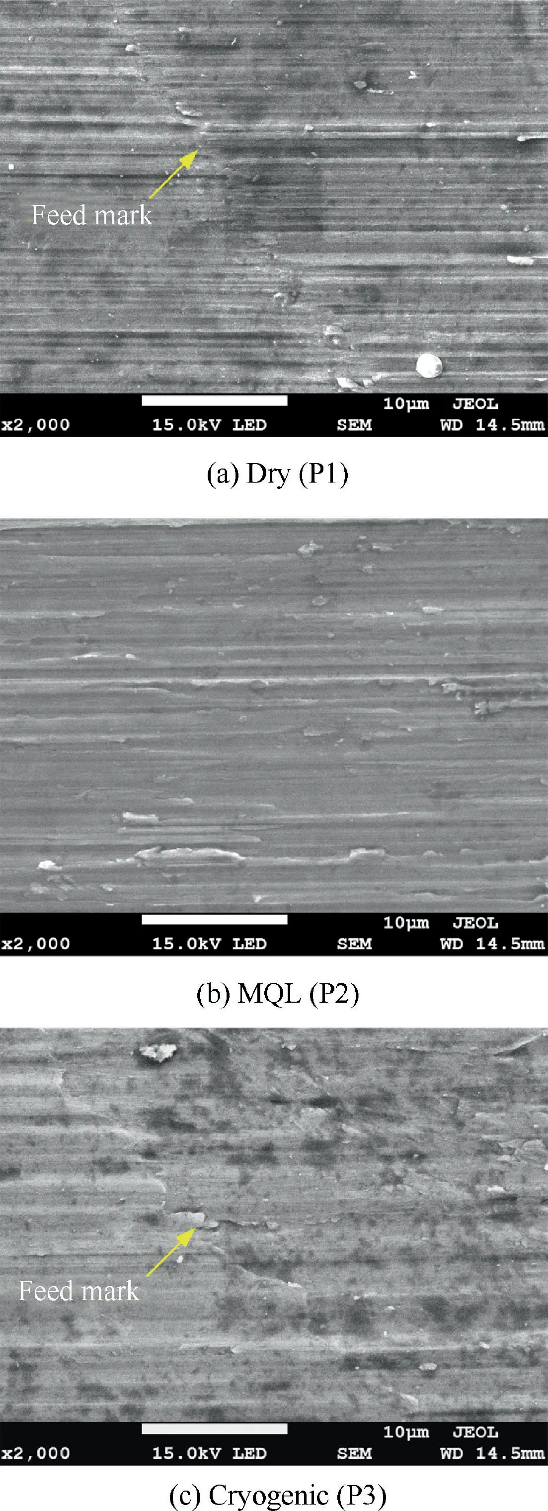
Fig.9 SEM observation of surface morphologies of No.1 hole for Ti-6Al-4 V layer at different cooling/lubrication conditions.
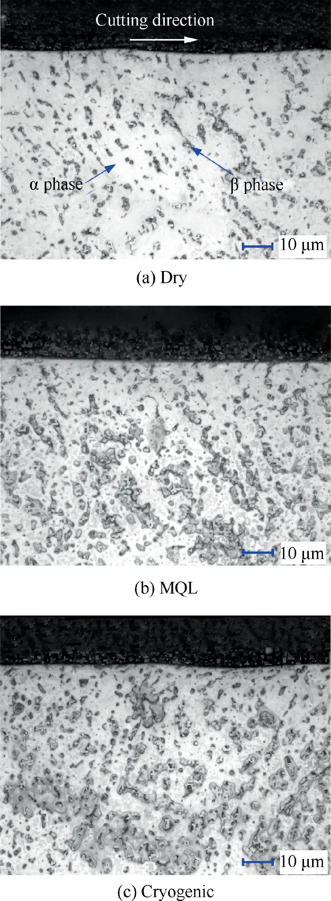
Fig.10 Metallography at cross section A of machined holes for Ti-6Al-4 V at different conditions.
To further study the hole damage of CFRP layer,the hole edge morphologies at the entrance of the machined holes(No.1 and No.7) are shown in Fig.11.For the first machined hole (No.1)with new tool,the hole entrance edges at all conditions exhibit good quality without obvious damage.While,for the seventh machined hole (No.7),damage exists at the area of acute fiber angle (the angle θ between the fiber direction and the cutting direction).Uncut fibers or burrs locate at the fiber angle range of 0°-45°,and tearing exists at the fiber angle range of 45°-90°,at both dry and MQL conditions,as illustrated in Fig.11(a1),(b1)and Fig.12.While only slight tearing is observed at the fiber angle range of 0°-90°at cryogenic condition.This indicates that CFRP entrance defects can be alleviated by HM at cryogenic condition,concerning the mechanism of material removal which was discussed in Section 3.2.1.
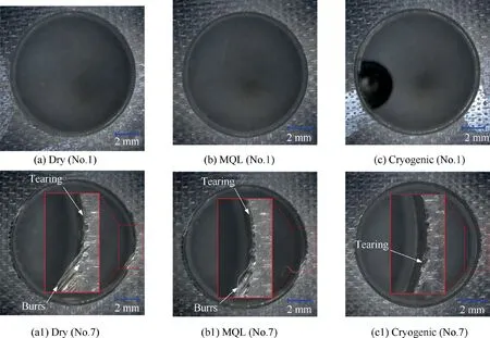
Fig.11 Morphologies of the entrance of CFRP of the first (No.1) and seventh (No.7) machined holes in different cooling/lubrication conditions.
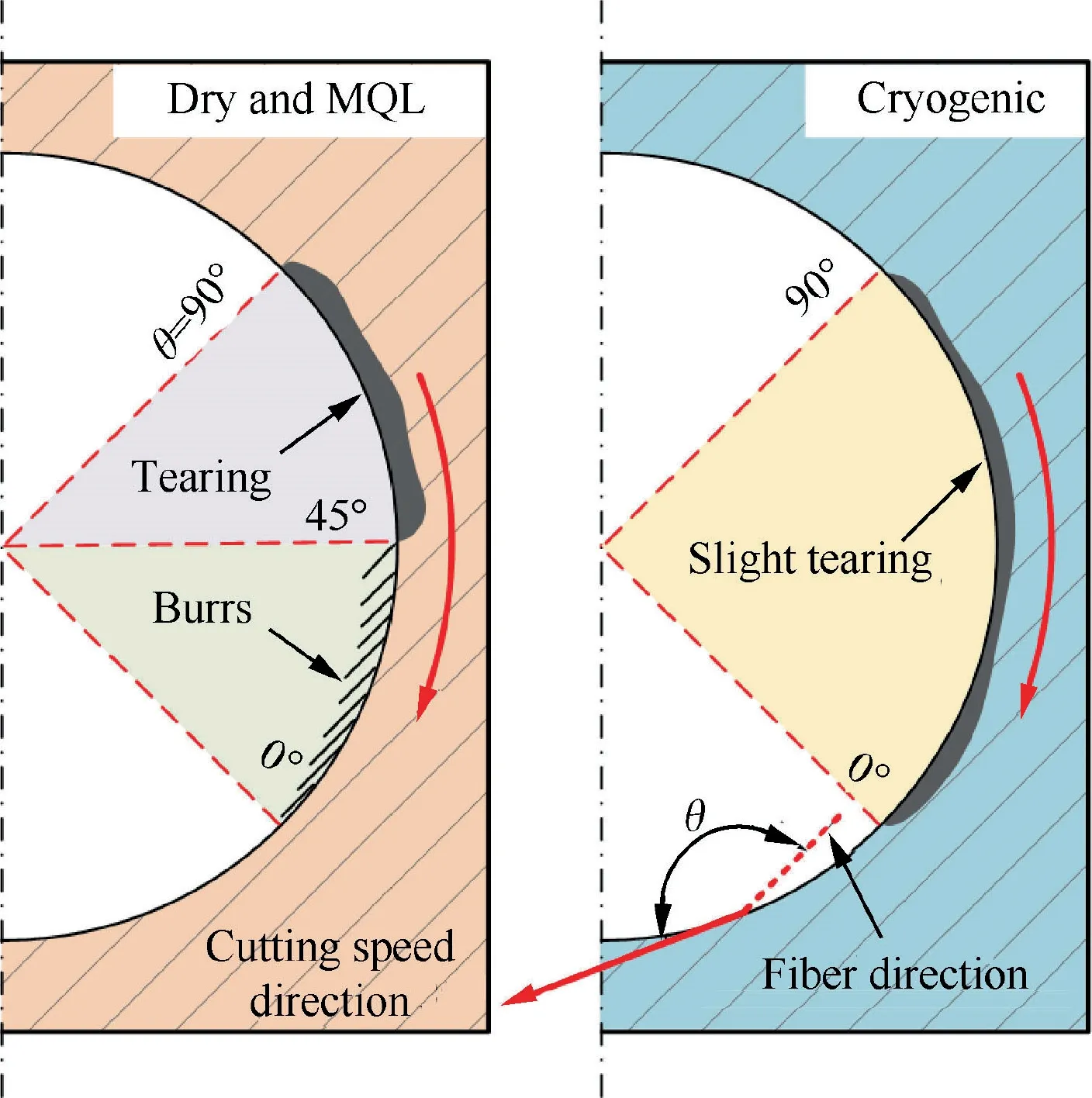
Fig.12 Schematic of damage at entrance of CFRP for different cooling/lubrication conditions.
As shown in Fig.13,the damage at the entrance of the CFRP plate are related with contact behaviors between cutting edge and fibers at the entrance.Note that the cutting process of the entrance of CFRP includes two stages which are related with different edges.At stage I,the CFRP entrance is cut by the rounded edge with edge radius of 0.5 mm,as shown in Fig.13(a).The rake angle of the bottom edge including the rounded edge is 0°,therefore,the cutting process when the rounded edge contact with fibers can be seen as orthogonal cutting with rake angle of 0°.At stage II,the fibers and resin at CFRP entrance contact with the peripheral edge,which can be considered as an oblique cutting process.
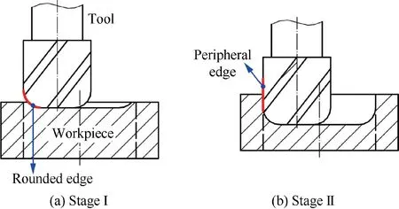
Fig.13 Cutting processes of CFRP entrance.
According to our previous study,the cutting process related with peripheral edges in HM was transformed to oblique cutting,and the inclination angle λof peripheral edges in HM can be expressed as

where δ is the helix angle of tool,γ is the angle between the direction of cutting speed and horizontal plane,is the vertical feed velocity,andis the cutting speed in horizontal plane at a point on the hole wall.andcan be calculated by

whereis the number of tool edges,is the spindle speed,is the axial feed,is the tangential feed per tooth,is the eccentric distance of HM,is the radius of milling tool,andis the orbital revolution speed,which can be obtained by

The effective rake angle αof tool edges in oblique cutting can be calculated by

where αis the normal rake angle of peripheral edges.According to the calculating method proposed by Liu et al.,the equivalent fiber cutting angle θ’ in oblique cutting can be obtained by

where θ is the original fiber cutting angle defined in orthogonal cutting process.Substitute the cutting parameters and tool geometry parameters into above equations,the corresponding parameters λ,αand θ’can be obtained in the cutting process of stage II.In this work,the λis approximately equal to 38°,and αis calculated as 25.7°.
The tool and fiber contact state at the cutting processes of stages I and II are transformed to orthogonal cutting processes based on the calculated results,as illustrated in Fig.14.For 0°<θ <45° (stage I in Fig.14(a)) and 38°≤θ’≤56.1° (stage II in Fig.14(a1)),the main fiber fracture characteristics are extrusion and shearing at stage I,while mainly shearing at stage II.Burrs are generated at stage I when the rounded edges are badly worn.Meanwhile,it is difficult for peripheral edges to cut off the burrs without the support of matrix,considering the equivalent fiber cutting angle θ’ in stage II.For 45°<θ <90° (stage I in Fig.14(b)) and 56.1°≤θ’≤90° (stage II in Fig.14(b1)),the main fracture characteristics should be shearing in both stage I and stage II.The fibers may be pulled out when tool wear is large,then the tearing damage occurs.For 90°<θ <180° (stage I in Fig.14(c)) and 90°≤θ’≤142° (stage II in Fig.14(c1)),fibers can be fractured easily by bending.Thus,there is no obvious damage in this fiber angle range with the increase of tool wear.
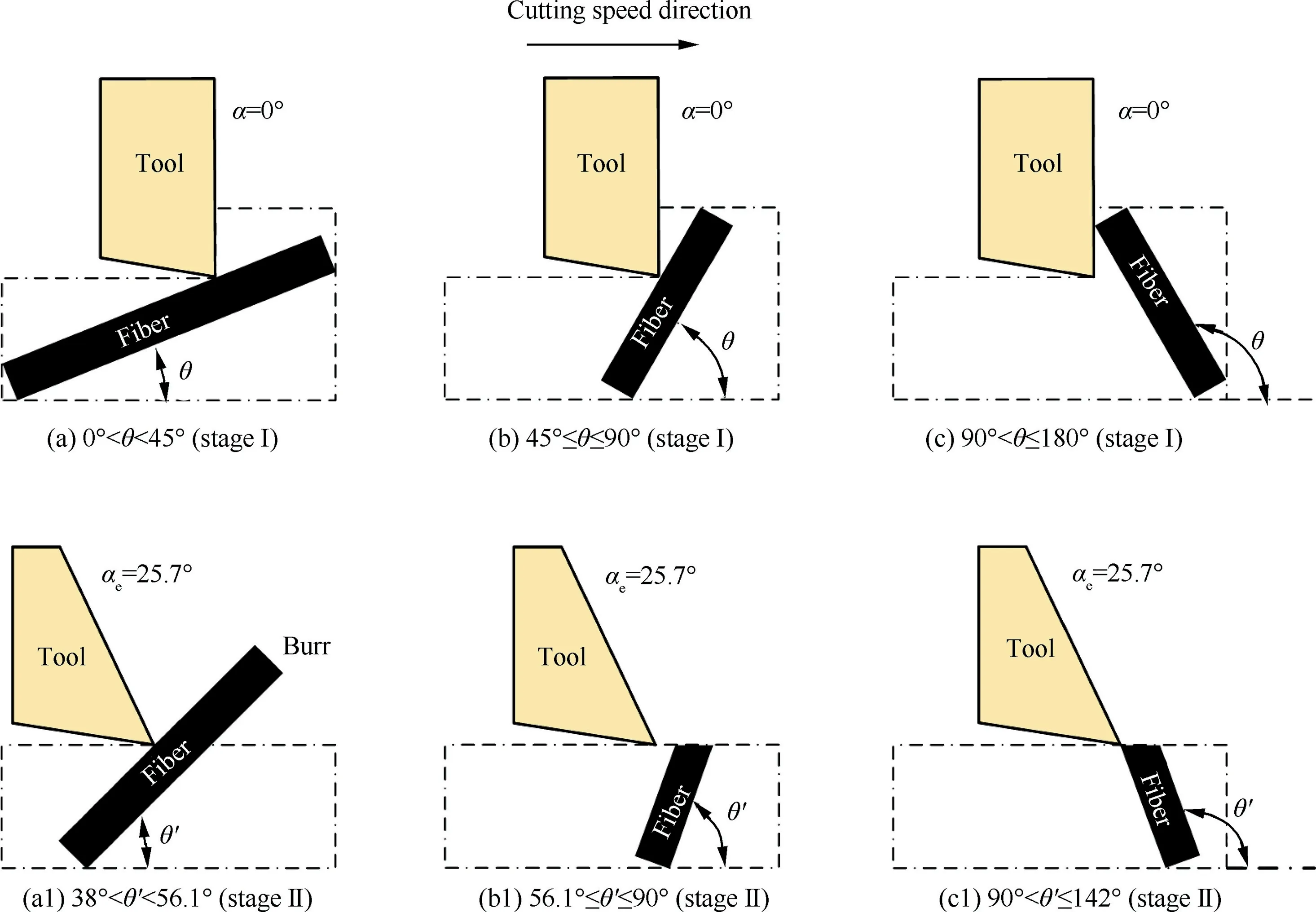
Fig.14 Schematic of cutting according to calculated tool rake angles (effective rake angles) and fiber angles (equivalent fiber angles).
In this work,the heights of exit burrs in Ti-6Al-4 V layer were measured by a dial test indicator and shown in Fig.15.Burrs were generated at the fifth,seventh and third holes in dry,MQL and cryogenic conditions,respectively.That is,Burrs are easily formed at cryogenic condition,while MQL is helpful to eliminate the burrs,for the given machining parameters.The average burr heights in Dry and MQL conditions varies from 0.69 mm to 0.94 mm,while it ranges from 0.66 mm to 1.19 mm in cryogenic condition.Burrs formation is highly related to the tool wear which will be discussed in section 3.4.It should be also related with the thermal-plastic behavior of the material which is dependent on machining parameter and cooling condition.
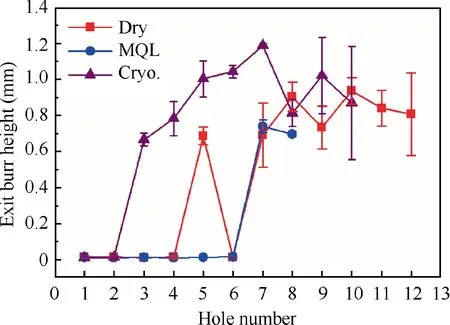
Fig.15 Measured height of exit burrs of Ti-6Al-4 V layer.
To further indicate the hole damage at the whole thickness of CFRP,the delamination factorwas used to characterize the delamination,and the delamination factor is given as

whereis the maximum diameter of delamination,is the nominal diameter.These values were measured by the C-scan acoustic microscope.The calculated delamination factors are shown in Fig.16.For most conditions,the delamination factors increase almost linearly with the increase of hole number.Additionally,the delamination factors at dry condition are higher than other conditions when the machined hole number is less than eight.While,the delamination factors at cryogenic condition are smaller than dry and MQL conditions for holes No.1-No.8,indicating better surface quality with less delamination.This is consistent with the surface morphologies in Section 3.2.1.It is worth noting that the delamination factors of No.9 and No.10 are higher than other conditions.That should be caused by the breakage of cutting edge which will be discussed at section 3.4.Note that the resultant and axial forces of holes No.9 and No.10 for CFRP at cryogenic condition exhibited higher values (Fig.5(a),(b)) than those of holes Nos.1-8,which indicates that larger resultant and axial forces for same cooling condition can lead to the increase of delamination damage.
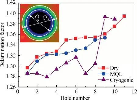
Fig.16 Delamination factors of CFRP holes at different cooling/lubrication conditions.
3.3.Machined hole diameter
To investigate the geometrical accuracy of machined holes of the CFRP/Ti-6Al-4 V stacks,hole diameter errors at different axial positions (-1 mm,-2.7 mm,-4.4 mm,-6.4 mm,-7.9 mm and-9.4 mm)of hole No.1 at different cooling conditions were measured by coordinate measuring machine and shown in Fig.17.It is noted that the hole diameter errors vary along the axial direction with a ‘‘spoon-like” shape.That is,the hole diameters near the interface of the stacks (at-2.7 mm and -4.4 mm) are larger than those at the entrance(-1 mm) of CFRP and at Ti-6Al-4 V layer.Meanwhile,the hole diameters at the entrance of CFRP layer are very close to those of Ti-6Al-4 V layer for all cooling/lubrication conditions.That should be caused by the generation of titanium alloy chips which can scrape the CFRP surface near the interface.Additionally,the variation of hole diameter (error) at MQL condition(approximately 0.02 mm)is smaller than those at dry (about 0.037 mm) and cryogenic (about 0.03 mm) conditions,since MQL is beneficial to lubricating the contact behavior between the titanium alloy chips and CFRP surface.
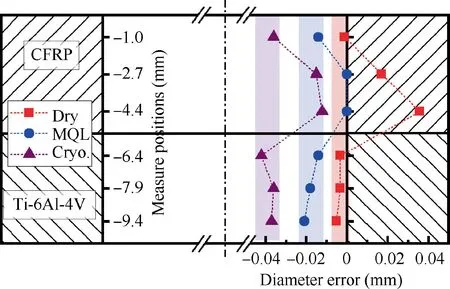
Fig.17 Schematic of hole diameter error of hole No.1 at different cooling/lubrication conditions.
In addition,the hole diameters of holes No.1 and No.5 at different cooling/lubrication conditions were presented in Fig.18.Note that the hole diameters of the stacks at dry condition are higher than those at MQL and cryogenic conditions.Due to lower temperature at cryogenic condition,the resultant forces are higher than other cooling conditions.Higher resultant force may cause slightly larger tool deflection during HM of stacks,which will decrease the hole diameters.Additionally,hole diameter decreases with the increasing hole number due to the increased resultant forces caused by tool wear.Considering the hole diameters along the whole axial length(cylindricity),HM with MQL generates closer values to the target hole diameter.Besides,as indicated in Fig.17,hybrid cooling/lubrication maybe beneficial to achieving more accurate cylindricity.
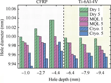
Fig.18 Measured hole diameters of holes No.1 and No.5 at different cooling/lubrication conditions.
3.4.Tool wear
Note that tool wear increases with the accumulated cutting time.To investigate the wear mechanism of cutting edges for different cooling/lubrication conditions,the final state of the bottom cutting edge was tested by SEM and Energy Dispersive Spectroscopy(EDS)analysis.The SEM results of final state of the bottom cutting edges at dry,MQL and cryogenic conditions are shown in Fig.19.For HM with dry condition,adhesion and small chipping wear are observed on the flank surface of the bottom cutting edge.While,for HM at MQL condition,slightly adhesion is observed due to the reduced friction effect by the lubrication.For cryogenic condition,adhesion and breakage exists at the bottom cutting edge and tool nose,due to higher cutting forces caused by the cryogenic cooling.Note that the breakage of bottom cutting edge happened after the eighth (No.8) hole was machined,since no cutting-edge breakage was observed by the optical microscopy when the hole No.8 was finished.
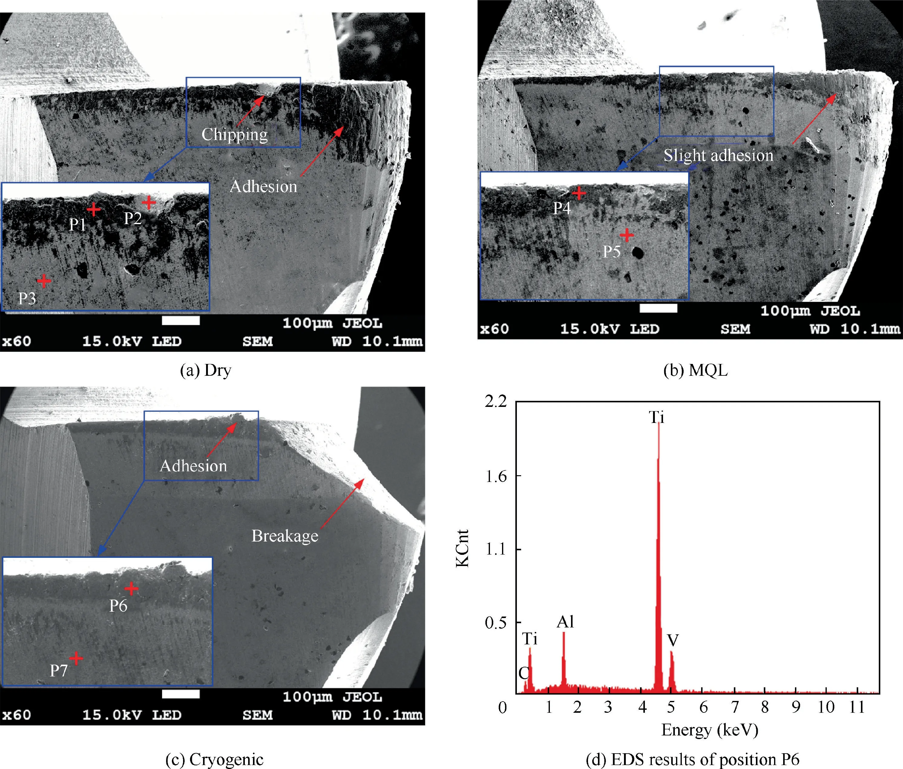
Fig.19 SEM results of final state of bottom cutting edges at different cooling/lubrication conditions.
To further illustrate the wear mechanism,the element mass fraction was measured by EDS.The results at different positions (P1-P7 in Fig.19(a)-(c)) are shown in Fig.19(d) and Table 3.According to the EDS results of the adhesion positions P1,P4 and P6,Ti,Al,V,C and O elements appeared at dry and MQL conditions,which indicates that the Ti-6Al-4 V alloy adhesion and oxide phenomena were generated due to the relatively high temperature in the cutting area.However,the Oxygen element did not exist at P6 in cryogenic condition,since the inputted LNcan protect the cutting area from being oxidized.The Ti,Al,V elements in position P2 indicates that adhesion may exist in the small chipping at dry condition.Additionally,similar mass fraction with elements of W,C,Co were tested at the areas without adhesion (P3,P5 and P7) at the dry,MQL and cryogenic conditions,respectively,indicating the matrix of the carbide components.
To quantitatively compare the tool wear at different cooling/lubrication conditions,the average flank wear (VB) in the middle of bottom cutting edge was measured after each two holes were machined by an optical microscopy.During the tests,the microscopy was installed on the worktable of the machining center and the milling tool was moved to the top of the microscopy to observe the tool wear.Therefore,the tool can be kept the same installed situation for each hole during the HM and tool wear tests.Fig.20 illustrated the average flank wear at different cooling/lubrication conditions.Note that tool wear at cryogenic condition increases almost linearly from approximately 50 μm to 180 μm until hole No.10 was machined.The tool wear at dry condition increases to about 130 μm when hole No.12 was machined.While,the tool wear at MQL condition is much smaller than those at dry and cryogenic conditions,the average flank wear is approximately 90 μm when eight holes were machined.Overall,cryogenic cooling generated the highest tool wear due to lower cutting temperature and higher cutting forces,while,the MQL condition generated the lowest tool wear considering the EDS results and the average flank wear during HM of CFRP/Ti-6Al-4 V stacks.
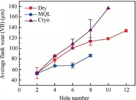
Fig.20 Average flank wear under different cooling/lubrication conditions.
4.Conclusions
In this work,helical milling experiments of CFRP/Ti-6Al-4 V stacks with dry,MQL and cryogenic with LNconditions were carried out to investigate the effect of sustainable cooling/lubrication on the performance and cutting mechanism of the stacks.The cutting forces and temperatures at various conditions were measured.The hole quality,including the hole surface morphologies,delamination of CFRP layer,hole diameter error and tool wear were discussed.This work provided new process solution for hole making of CFRP/Ti-6Al-4 V stacks considering the hole quality and tool wear.The main conclusions are given as follows:
(1) CFRP machining temperatures at cryogenic condition varied from-167°C to-94°C,which were much lower than those at dry and MQL conditions.The in-situ cutting load (thermal-mechanical load) temperatures for CFRP were much lower than the glass transition temperature,however,the post heat conduction temperature may exceed the value with the increase of tool wear.
(2) The resultant and axial forces at cryogenic conditions were much higher than those at dry and MQL conditions.Forces at dry and MQL conditions were close to each other due to the similar cutting temperatures.
(3) Fiber fracture surfaces of dry HM were almost perpendicular to the fiber axis,and the fiber fracture was primarily caused by tensile at dry condition.The fibers exhibited step-like fractured surface,exhibiting extrusion fracture characteristic due to the reduced friction effect at MQL condition.Cryogenic cooling contributed to more regular CFRP surface with smaller delamination factor and hole entrance damage,due to the increased resin strength and fiber brittleness.
(4) For Ti-6Al-4 V hole surfaces,MQL was beneficial to reducing the feed mark at the hole surface of Ti-6Al-4 V alloy.More severe deformation was generated at top surface of machine hole for cryogenic condition due to lower cutting temperature.
(5) Hole diameter errors varied along the axial direction with a ‘‘spoon-like” shape.It should be caused by the generation of titanium alloy chips which can scrape the CFRP surface near the interface.The cylindricity of holes machined by HM at MQL condition was better than those at dry and cryogenic conditions.
(6) Chipping and adhesion are the main tool wear for dry condition,while only slight adhesion tool wear was observed at MQL condition.Breakage happened after eighth machined hole at cryogenic condition,at which,no oxidize behavior exist in cryogenic condition,due to the liquid nitrogen inputted in the cutting area.
The authors declare that they have no known competing financial interests or personal relationships that could have appeared to influence the work reported in this paper.
This study was co-supported by the National Key Research and Development Program(No.2017YFE0111300)and Natural Science Foundation of China (No.51575384 and No.51675369).
 Chinese Journal of Aeronautics2022年2期
- Chinese Journal of Aeronautics的其它文章
- Pressure-induced instability and its coupled aeroelasticity of inflated pillow
- Adjoint boundary sensitivity method to assess the effect of nonuniform boundary conditions
- Transit time difference and equal or non-equal transit time theory for airfoils with lift
- A boundary surrogate model for micro/nano grooved surface structure applied in turbulence flow control over airfoil
- Nonlinear uncertainty quantification of the impact of geometric variability on compressor performance using an adjoint method
- High precision and efficiency robotic milling of complex parts:Challenges,approaches and trends
