Electrochemical cutting of mortise-tenon joint structure by rotary tube electrode with helically distributed jet-flow holes
Tao YANG,Xiaolong FANG,Xiaoyun HU,Zhengyang XU,Yongbin ZENG
Jiangsu Key Laboratory of Precision and Micro-Manufacturing Technology,Nanjing University of Aeronautics and Astronautics,Nanjing 210016,China
KEYWORDS Electrochemical cutting;Helically distributed holes;Jet-flow holes;Mortise-tenon joint structure;Rotary tube electrode
Abstract In aero-engines,mortise-tenon joint structures are often used to connect the blades to the turbine disk.The disadvantages associated with conventional manufacturing techniques mean that a low-cost,high-efficiency,and high-quality nickel-based mortise-tenon joint structure is an urgent requirement in the field of aviation engineering.Electrochemical cutting is a potential machining method for manufacturing these parts,as there is no tool degradation in the cutting process and high-quality surfaces can be obtained.To realize the electrochemical cutting of a mortise-tenon joint structure,a method using a tube electrode with helically distributed jet-flow holes on the side-wall is proposed.During feeding,the tube electrode rotates along its central axis.Flow field simulations show that the rotational speed of the tube electrode determines the direct spraying time of the high-speed electrolyte ejected from the jet-flow holes to the machining area,while the electrolyte pressure determines the flow rate of the electrolyte and the velocity of the electrolyte ejected from the jet-flow holes.The machining results using the proposed method are verified experimentally,and the machining parameters are optimized.Finally,mortise and tenon samples are successfully machined using 20 mm thick Inconel 718 alloy with a feeding rate of 5 μm/s.
1.Introduction
A mortise-tenon joint structure is often used to connect a blade to the turbine disk,and the manufacturing quality of these joints has a decisive impact on the reliability,safety,and performance of aero-engines.Therefore,the manufacturing requirements of such joints are very strict.In terms of material,nickel-based super alloys are widely used.Regarding the machining surface quality,it is important that there are no burrs,micro-cracks,recast layers,thermal effect layers,or other defects.
At present,turbine disk mortise-tenon joint structures for aero-engine enterprises are mainly machined using the broaching technique,which offers good consistency and high precision,and is suitable for mass production.However,broaching incurs considerable tool wear and high machining costs,because the nickel-based super alloy is difficult to cut.Moreover,the flexibility to adopt new designs is poor because a broach can only machine one type of mortise.Recently,to reduce machining costs and improve flexibility,low-speed wire electric discharge machining (WEDM) has been considered in an attempt to manufacture mortise-tenon joint structures for aero-engines by feeding a wire electrode across a twodimensional plane.Klocke et al.fabricated mortise samples by standard roughing,finishing,and surfacing,and the thickness of the surface recast layer was close to zero.WEDM significantly reduces the cost of machining mortise-tenon joint structures compared with broaching.However,WEDM inevitably leaves a recast layer and a heat effect layer on the machined surface,which reduces the machining quality and shortens the service life of the components.At present,WEDM cannot satisfy the high efficiency and cutting-quality requirements for the mortise-tenon joint structures of aircraft engines.
Electrochemical cutting is a form of machining technology in which a wire,rod,or tube is used as the tool electrode to cut the workpiece over a 2D plane.In the cutting process,the workpiece and tool electrode,which are respectively connected with the positive and negative poles of the power supply,undergo an oxidation-reduction reaction in the electrolyte.The local materials of the workpiece are corroded and removed in the form of ions,enabling high-accuracy machining that is free from recasting layers,micro-cracks,and burrs.Moreover,there is always a certain machining gap between the two electrodes,so no machining stress is generated.In addition,the tool electrode does not wear out because it is not corroded and only hydrogen bubbles are generated on its surface.These machining characteristics suggest that electrochemical cutting is a superior method for manufacturing mortise-tenon joint structures.
However,there is a disadvantage to the electrochemical cutting process,namely that it is difficult to quickly remove bubbles and insoluble electrolytic products from the narrow machining gap.The accumulation of a large number of bubbles and insoluble electrolytic products affects the electric field distribution between the workpiece and the tool electrode,resulting in the reduced machining efficiency and accuracy,or even machining failure.As the workpiece thickness increases,this phenomenon becomes more prominent.Thus,electrochemical cutting has not been widely applied in industry.
Many attempts have been made to enhance the mass transfer in the machining gap,thereby improving machining efficiency and the ability to machine large-thickness workpieces.The auxiliary movement of the wire electrode along the direction of workpiece thickness has been examined,as the relative movement between the two electrodes can ‘‘drag out” the waste electrolyte with electrolytic products from the machining gap.The electrochemical cutting of a 20-mm-thick stainless steel workpiece was realized using high-speed reciprocating movement of the wire electrodeand low-speed monodirectional movement of a ring wire electrode.To enhance the dragging effect,a method of electrochemical cutting assisted by large-amplitude vibrations of a ribbed electrode was proposed.The micro-groove structure on the surface of the ribbed electrode promotes the flow of electrolyte and enhances the transmission of electrolytic products.Finally,a bar code structure was machined at a feed rate of 2.4 μm/s on a 5-mm-thick stainless steel substrate.In addition,the cutting efficiency can be improved by using a tool electrode with a noncircular cross-section,such as cutting edge tools and helical tools,as their high-speed rotary movement stirs the electrolyte flow and promotes the diffusion of electrolytic products in the machining gap.
The above methods machine the workpiece while it is immersed in the static electrolyte,so the flow of electrolyte is still slow and the improvement in machining efficiency is not significant.For this reason,electrochemical cutting with electrolyte flushing has been proposed,whereby an electrolyte with a high flow velocity is directly squirted into the gap and quickly flushes out the electrolytic products,thus renewing the electrolyte.For example,He et al.adopted an axial electrolyte flushing method to cut complex slit structures on a 10-mm-thick Ti-42Al-6 V-1Cr alloy at a feed rate of up to 3.0 μm/s.On this basis,Klocke et al.used a tool electrode twisted around two wires to further accelerate the flow velocity of the electrolyte in the narrow and long machining gap under the action of high-speed rotary movement.This enabled them to realize electrochemical cutting of a 40-mm-thick workpiece with a feed rate of 8.3 μm/s.However,the flow velocity of the electrolyte at the upper and lower ends of the slit was different,and the consistency of the slit width was poor.To avoid this phenomenon,a metal tube with array holes can be used as the tool electrode.This allows the entire machining area to be directly flushed by fresh electrolyte ejected from the holes,thus improving the uniformity of electrolyte flow in the machining gap.A fan-shaped array of columns has been fabricated on a 10-mm-thick stainless steel block at a feed rate of 7 μm/s.At present,this method can only machine straight slit structures,because the tube electrode can only perform relative feed movement in the direction of electrolyte injection.
To realize the electrochemical cutting of mortise-tenon joint structures,a method of electrochemical cutting using a tube electrode with helically distributed jet-flow holes on the sidewall is proposed.During the feeding process,the tube electrode rotates along its central axis.The effects of tube electrode rotational speed and electrolyte pressure on machining results are verified through simulations and experiments,and the machining parameters are optimized.Finally,samples of mortises and tenons are successfully machined on 20-mmthick Inconel 718 workpieces at a feeding rate of 5 μm/s using the optimal machining parameters.
2.Principle of electrochemical cutting using rotary tube electrode
Fig.1(a)shows a schematic diagram of electrochemical cutting using a rotary tube electrode.The tube electrode is a metal tube with a closed bottom and three rows of jet-flow holes with an average helical distribution on the sidewall,as shown in Fig.1(b).The electrolyte enters from the inlet at the top of the tube electrode under high pressure,and rapidly sprays into the machining gap from the jet-flow holes on the sidewall.Under the action of an external voltage,an electrolytic reaction occurs between the two electrodes,and the electrolytic products in the machining gap are washed away.The tube electrode performs a relative feeding movement with respect to the workpiece in the two-dimensional horizontal plane.Additionally,the tube electrode makes a rotary movement along its own central axis,so that the electrolyte ejected from each row of jet-flow holes can be sprayed in any direction on the horizontal plane,realizing multi-directional cutting of the workpiece.The workpiece makes a reciprocating movement along its thickness direction,so as to change the spraying position of electrolyte on the machining surface and improve the uniformity of electrolyte flow in the machining gap.
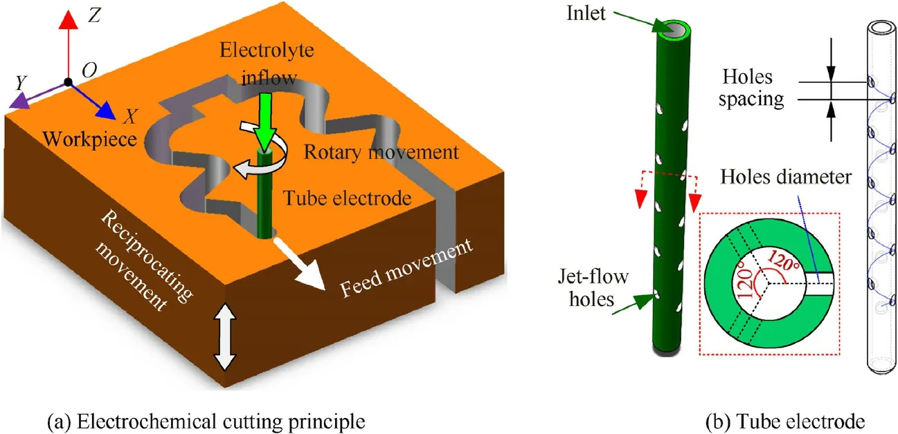
Fig.1 Schematic diagram of electrochemical cutting using rotary tube electrode.
To clarify the flow state of the electrolyte in the machining gap,a flow field model of the electrolyte was established,as shown in Fig.2.When the spray direction of the electrolyte is consistent with the relative feed direction,it is set as the starting position of the tube electrode rotation.Flow field simulation analysis was carried out at 6°-rotation intervals.The simulation and experiment have proved that the optimal spacing between the array jet-flow holes on the tube electrode is 1 mm when the reciprocating motion of the workpiece are 1 mm and 1.5 Hz respectively.Therefore,the jet-flow holes spacing was set as 1 mm in this study.In order to ensure that the height of the electrolyte injection range is equal to the thickness of workpiece (20 mm),the number of array holes is set as 21.The simulation parameters are presented in Table 1.The vertical section at=0 mm and cross-sections at=1 mm,=10 mm,and19 mm were chosen to illustrate the flow velocity distribution of the electrolyte in the machining gap.The line(=0.425 mm and=0 mm)and point(=0.425 mm,=0 mm,and=10 mm)are referenced to describe the specific electrolyte flow velocity.
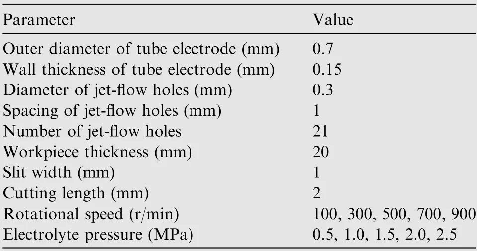
Table 1 Simulation parameters.
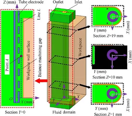
Fig.2 Flow field model of electrolyte in machining gap.
Fig.3 illustrates the flow field state of the electrolyte in the machining gap when the tube electrode rotates three times at a rotational speed of 500 r/min.As can be seen from Fig.3,as the tube electrode rotates,the machining gap is filled with electrolyte,which ensures the normal occurrence of electrolytic reaction.Fig.4 was obtained by extracting and fitting the flow velocity on linewithin the machining gap.There is clearly a large difference in the flow velocity of the electrolyte in the machining gap.The flow velocity in the area directly sprayed by the electrolyte is very high,whereas that in the area not directly sprayed by the electrolyte is relatively low.In order to improve the uniformity of electrolyte flow field in machining gap,the jet-flow holes on the tube electrode are helically distributed,which makes the height of the electrolyte ejected from every jet-flow holes sprays to the machining gap different.Fig.5(a)-(c) show the spraying state of electrolyte from the tube electrode cavity to the machining gap at different moments during the rotation of the tube electrode.With the continuous rotation of the tube electrode,the electrolyte flow in the whole machining gap changes periodically.During the whole rotating process,the spraying state of electrolyte from the tube electrode cavity to the whole machining gap is shown in Fig.5(d).This indicates that the rotary movement of the tube electrode with helically distributed jet-flow holes improves the overall flow uniformity of the electrolyte in the machining area.
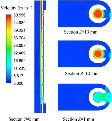
Fig.3 Flow velocity contours of electrolyte on different sections(when the tube electrode rotates to the third cycle at a rotational speed of 500 r/min).
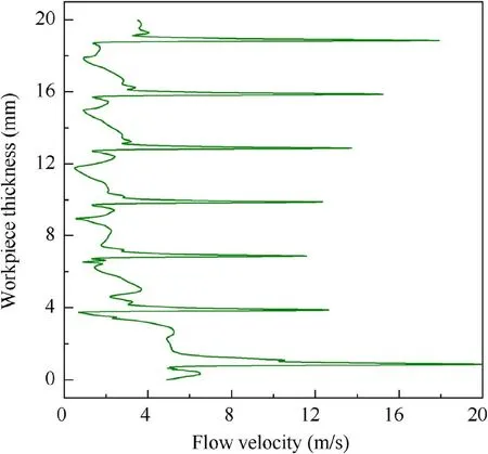
Fig.4 Flow velocity of electrolyte on line L(when tube electrode rotates to third cycle at a rotational speed of 500 r/min).
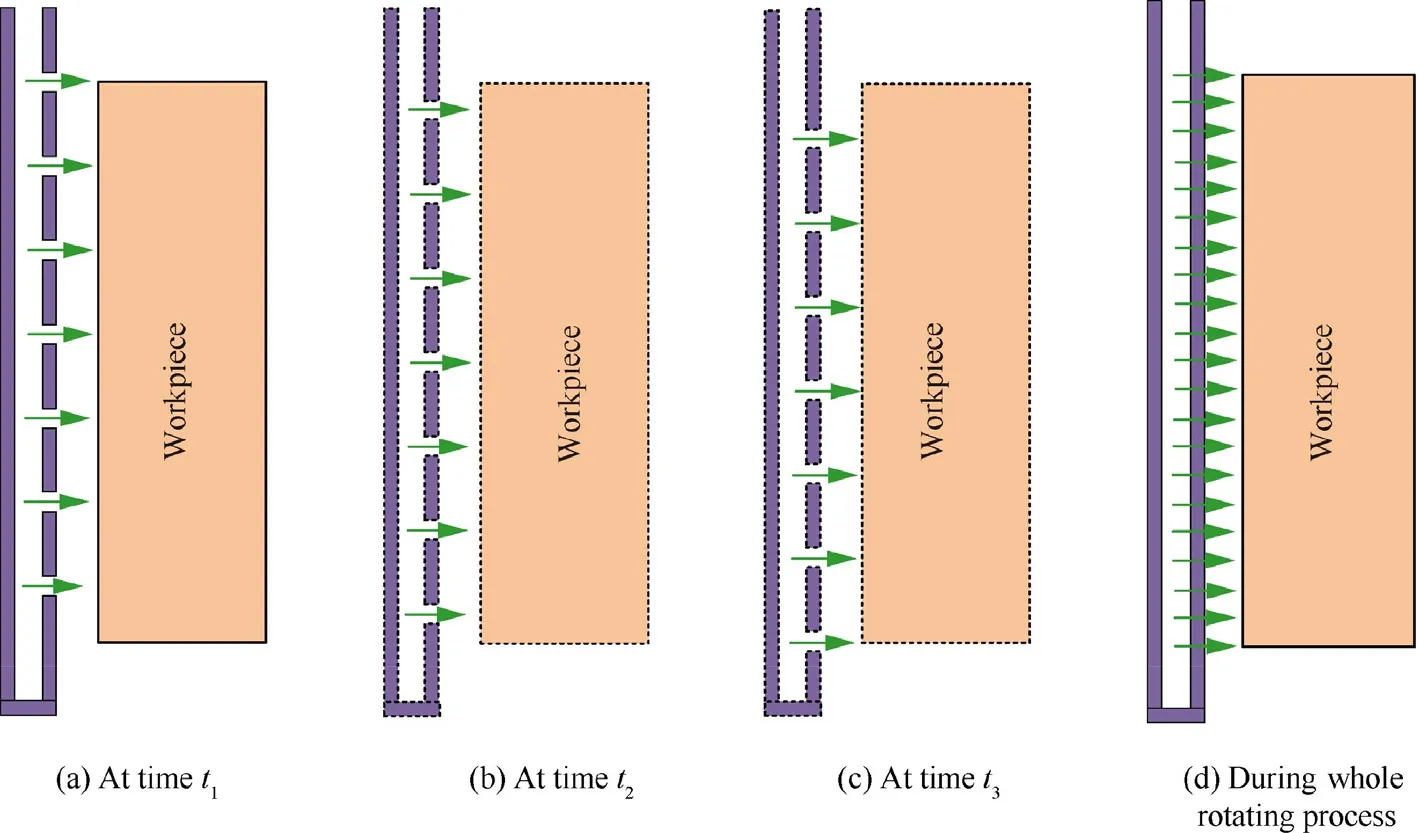
Fig.5 Spraying state of electrolyte in machining gap during rotating movement of tube electrode.
Fig.6 shows the electrolyte flow velocity at different moments at pointwhen the rotational speed of the tube electrode is 100 r/min and 500 r/min.It can be seen that the rotary movement of the tube electrode changes the direct spraying time of the electrolyte ejected from the jet-flow holes onto the machining area.The higher the rotational speed of the tube electrode,the more the direct spraying times of the electrolyte with high flow velocity to the machining area,which promotesthe flow of electrolyte and facilitates the removal of electrolytic products.
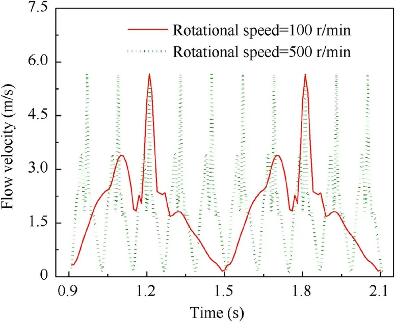
Fig.6 Variation in electrolyte flow velocity with time at point A for rotational speeds of 100 r/min and 500 r/min.
According to Bernoulli’s equation,the flow velocity of the electrolyte will increase as the electrolyte pressure increases,all other variables remaining constant.When the flow area is invariable,a faster flow velocity produces a larger flow rate through the machining area.When the rotational speed of the tube electrode is 500 r/min,Fig.7 shows the flow velocity of electrolyte at pointunder electrolyte pressures of 0.5 MPa and 2.5 MPa.As the electrolyte pressure increases from 0.5 MPa to 2.5 MPa,the flow velocity increases significantly and the maximum flow velocity increases from 3.24 m/s to 7.23 m/s.The simulated electrolyte flow rate in the machining gap is shown in Fig.8.The electrolyte flow rate increases from 11.662 L/h to 26.704 L/h when the electrolyte pressure increases from 0.5 MPa to 2.5 MPa.A larger flow rate and higher flow velocity of electrolyte are more conducive to the removal of electrolytic products and the occurrence of an electrolytic reaction.
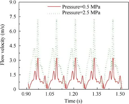
Fig.7 Variation in electrolyte flow velocity with time at point A for electrolyte pressures of 0.5 MPa and 2.5 MPa.

Fig.8 Flow rate of electrolyte under different electrolyte pressures.
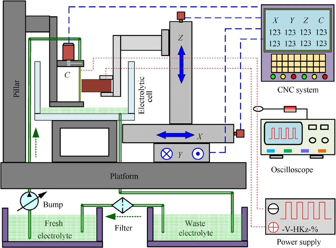
Fig.9 Schematic diagram of experimental equipment.
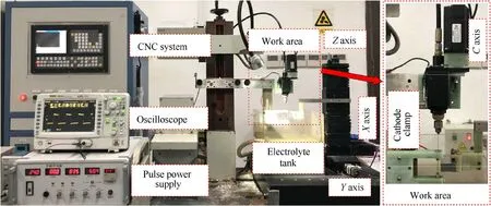
Fig.10 Photograph of experimental equipment.
3.Experimental equipment and procedures
To verify the influence of the rotary tube electrode on electrochemical cutting,special experimental equipment was set up,including a computer numerical control (CNC) system,fouraxis machine tool,electrolyte circulation system,special cathode fixture,anode fixture,pulse power supply,and digital oscilloscope.A schematic diagram and photograph of this setup are shown in Figs.9 and 10,respectively.The/-axis is used to drive the workpiece to move in the horizontal plane and realize the relative feed movement between the workpiece and the tube electrode.The-axis is used to drive the workpiece to reciprocate movement along its thickness direction,so as to change the spraying position of the electrolyte onto the machining surface and improve the uniformity of electrolyte flow in the machining gap.The-axis is used to drive the rotary movement of the tube electrode along its central axis,so as to change the spraying direction of the electrolyte in the horizontal plane and realize multi-directional cutting.The electrolyte circulation system mainly consists of a pressure pump to drive the high-speed flow of the electrolyte and a filter for insoluble electrolytic products.Under the action of the pressure pump,the fresh electrolyte enters the inner cavity of the tube electrode along the pipeline and is ejected from the jet-flow holes.The waste electrolyte generated after the electrolysis reaction drips into the electrolytic cell,and then flows back to the electrolyte tank along the pipeline.Finally,it is filtered and turned into fresh electrolyte.The special cathode clamp is mainly used to ensure that the connection between the tube electrode and the pipeline is properly sealed as the tube electrode is rotating.The frequency of the pulse power supply,which provides the electric energy needed for the electrolytic reaction,ranges from 1-100 kHz;this guarantees the efficiency and improves the accuracy of electrochemical cutting.The current signal detected by the oscilloscope is used to determine the stability of the machining process.
Inconel 718 samples of length 60 mm,width 35 mm,and height 20 mm were polished and ultrasonically cleaned before the experiment.The selected machining parameters are presented in Table 2.Photographs of the machining process at different points in time are shown in Fig.11.
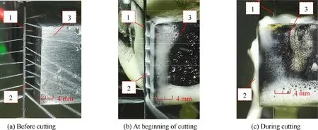
Fig.11 Machining scene photographs at different moments (1:tube electrode,2:electrolyte,and 3:workpiece).
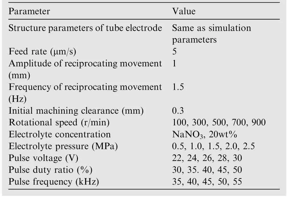
Table 2 Machining parameters.
According to Ohm’s law and Faraday’s law,the following relation between the feed rate and machining gap can be obtained when the electrochemical machining reaches a balanced state:

whereis the feed rate,η is the current efficiency,ωis the volumetric electrochemical equivalent,is the current density,κ is the conductivity of the electrolyte,is the inter-electrode voltage,and Δis the balanced machining gap.However,the conductivity of the electrolyte in the machining gap is always variable due to the influence of bubbles and insoluble electrolytic products in the actual machining.An approximate formula for this parameter is given by:

where κis the initial conductivity of the electrolyte and β is the fraction of electrolytic products.
For electrochemical cutting,the distribution of the machining gap is shown in Fig.12.Δis the side machining gap,is the outer diameter of the tube electrode,andis the slit width.
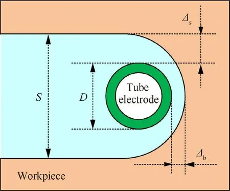
Fig.12 Machining gap distribution in the process of electrochemical cutting using a tube electrode.
In the process of stable electrochemical cutting,the relationship between the side machining gap and the balance machining gap can be expressed as:

Therefore,the slit width can be calculated as:

In the process of electrochemical cutting using a rotary tube electrode,the rotational speed of the tube electrode and the pressure of the electrolyte affect the flow state of the electrolyte.According to Eq.(2),the flow state of the electrolyte affects the electrolyte conductivity.Additionally,the applied electrical parameters affect the inter-electrode voltage.It can be seen from Eq.(1)that,for a constant feed rate,the conductivity of the electrolyte and the inter-electrode voltage affect the balanced machining gap.Eqs.(3) and (4) imply that a change in the machining gap affects the slit width.Therefore,the slit width indirectly reflects the influence of the electrode rotational speed,electrolyte pressure,and applied electrical parameters on the machining process.The machined sample is ultrasonically cleaned and the cut slit is detected.The morphology of the machined slit was captured by a Leica microscope (DVM500,Germany) and the width of the slit was measured using an Olympus microscope (SMT7-SFA,Japan).In addition,the roughness of the machined slit wall was measured in terms of the Taylor form using surface measurement apparatus (FTS-5,England).
4.Results and discussion
4.1.Effect of rotational speed
A slit-cutting experiment was carried out to explore the effect of the rotational speed of the tube electrode on the machining process under an electrolyte pressure of 1.5 MPa and electrical parameters of 26 V (pulse voltage)-40% (pulse duty ratio)-50 kHz (pulse frequency).Fig.13 shows the effect of the rotational speed on the slit width,standard deviation of slit width,and roughness.
As can be seen from Fig.13,the slit width gradually increases as the rotational speed of the tube electrode rises.This is because a greater rotational speed increases the direct spraying time of the electrolyte ejected from the jet-flow holes onto the machining area,enhances the removal rate of electrolytic products,and increases the electrolytic reaction rate.Therefore,a larger slit width can be achieved at the same feed rate.
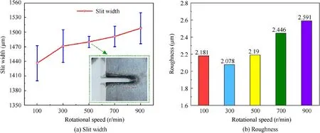
Fig.13 Machining results with respect to rotational speed of tube electrode.
At rotational speeds of up to 500 r/min,any increase in the rotational speed decreases the standard deviation of the slit width and improves the consistency of the slit width.This is because the faster rotational speed of the tube electrode results in smoother removal of the electrolytic products from the machining gap,decreases the influence of electrolytic product on the conductivity of the electrolyte in the machining gap,makes the electric field distribution more uniform,and enhances the consistency of the slit width.For the same reason,the slit wall is smoother under a rotational speed of 300 r/min than when the rotational speed of the tube electrode is 100 r/min.
The flow path of the electrolyte during the cutting process is shown in Fig.14.The waste electrolyte,containing a large number of bubbles and insoluble electrolytic products,is washed from the machining gap into the machined slit by the fresh electrolyte ejected from the jet-flow holes,and finally flows out of the slit along the back of the tube electrode.The photograph in Fig.11(c) verifies this phenomenon.The waste electrolyte produces secondary electrochemical corrosion on the machined slit wall.As the rotational speed of the tube electrode increases,the slit width increases and the amount of material removed grows.At the same time,more bubbles and insoluble electrolytic products are produced,and these have a greater influence on the current density distribution in the machined slit.Therefore,the standard deviation gradually increases as the rotational speed of the tube electrode increases above 500 r/min.In the same way,the slit wall gradually becomes rougher as the rotational speed increases above 300 r/min.
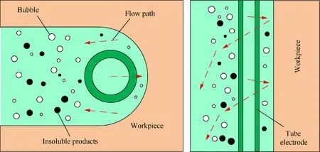
Fig.14 Schematic diagram of electrolyte flow path.
4.2.Effect of electrolyte pressure
A slit-cutting experiment was carried out to explore the effect of electrolyte pressure on the machining process.The rotational speed of the tube electrode was set to 500 r/min and the electrical parameters were 26 V-40%-50 kHz.Fig.15 shows the effect of the electrolyte pressure on the slit width,standard deviation of slit width,and roughness.
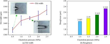
Fig.15 Machining results with respect to electrolyte pressure.
It can be seen from Fig.15 that the electrolyte pressure has a considerable influence on the machining.As the electrolyte pressure increases from 0.5 MPa to 2.5 MPa,the slit width increases from 1395 μm to 1537 μm.When the electrolyte pressure is 0.5 MPa,the machining fails and the cut length is only 3.614 mm.This is because the electrolyte pressure is too low,and so the electrolyte sprayed into the machining gap has a low flow rate and slow flow velocity.The electrolytic products cannot be quickly removed from the machining gap,resulting in a reduction in electrolyte conductivity (according to Eq.(2))and reduced material removal rate.When the relative feeding rate is too fast,the tube electrode comes into contact with the workpiece,resulting in a short circuit and machining failure.When the electrolyte pressure is greater than 1.0 MPa,the machining can proceed smoothly.The slit width increases gradually with an increase in electrolyte pressure.This is because an increase in electrolyte pressure enhances the flow rate and flow velocity of the electrolyte.This in turn increases the amount of fresh electrolyte available for electrolytic reaction,accelerates the removal of electrolytic products,improves the material removal rate,and widens the slit under the same feed rate.
When the electrolyte pressure is 1.5 MPa,the fresh electrolyte sprayed into the machining gap has a large flow rate and high flow velocity,which imposes a large flushing action on the electrolytic products and accelerates their removal compared with an electrolyte pressure of 1.0 MPa.The electrolyte conductivity in the machining gap is highly consistent and the electric field distribution is more homogeneous,so the standard deviation of the slit width decreases.
As the electrolyte pressure increases from 1.5 MPa to 2.5 MPa,the standard deviation of the slit width gradually increases.The increase in electrolyte pressure accelerates the electrolytic reaction and increases the amount of electrolytic products.The number of bubbles and insoluble electrolytic products washed away by fresh electrolyte from the machining gap to the machined slit increases,resulting in uneven conductivity of the electrolyte,inconsistent distribution of the electric field and flow field in the machined slit,and a variable removal rate of secondary electrochemical corrosion on the machined slit wall.This is why the slit wall becomes rougher as the electrolyte pressure increases.
4.3.Effect of electrical parameters
A slit-cutting experiment was carried out to explore the effect of the electrical parameters on the machining process.The rotational speed of the tube electrode was set to 500 r/min and the electrolyte pressure was 1.5 MPa.Figs.16-18 show the effect of the pulse voltage,pulse duty ratio,and pulse frequency on the slit width,standard deviation of slit width,and roughness.
It can be seen from Fig.16 that the slit width increases with an increase in the pulse voltage.The pulse voltage determines the current density in the machining gap,with a higher pulse voltage producing a higher current density and a faster material removal rate.At the same feed rate,more material being removed per unit length leads to a wider slit.It can be seen from Fig.17 that increasing the pulse duty ratio increases the slit width.The pulse duty ratio determines the effective power-on time per unit time.Thus,a greater duty ratio implies a longer electrolytic reaction time between the tube electrode and the workpiece,a greater amount of material removed,and a wider slit.Fig.18 shows that the slit width gradually decreases with any increase in pulse frequency.This is because the charging and discharging time of the double layer under high-frequency-pulse electrochemical machining is usually a constant.An increase in the pulse frequency shortens the pulse cycle length,thus reducing the effective machining time per cycle.Therefore,the amount of material removed in the same time period decreases and the slit narrows.
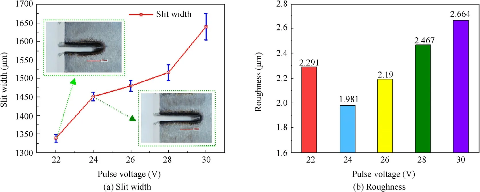
Fig.16 Machining results with respect to pulse voltage (pulse duty ratio is 40% and pulse frequency is 50 kHz).
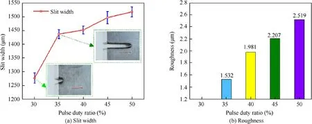
Fig.17 Machining results with respect to pulse duty ratio (pulse voltage is 24 V and pulse frequency is 50 kHz).
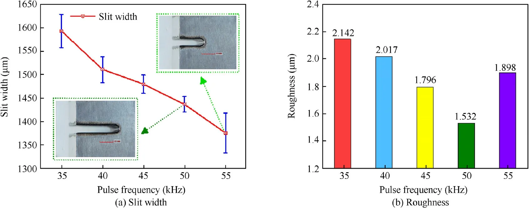
Fig.18 Machining results with respect to pulse frequency (pulse voltage is 24 V and pulse duty ratio is 35%).
When the pulse voltage is too low (22 V),the pulse duty ratio is too small (30%),and the pulse frequency is too high(55 kHz),the material removal rate is low due to the small amount of electric energy available.The tube electrode contacts the workpiece under the fast feed rate,resulting in a short circuit and machining failure.Therefore,the surface quality of the machined slit wall will be poor.
Figs.16-18 also indicate that the standard deviation of slit width and roughness increase as the slit width becomes greater during the normal electrochemical cutting process.This is because more electrolytic products are produced as the slit width increases.Excessive electrolytic products affect the conductivity of waste electrolytes in the slit,worsen the distribution of the electric field,and reduce the consistency and surface quality of the slit.
4.4.Machining of mortise and tenon samples
According to the experimental results described above,the optimal machining parameters were selected:the rotational speed of the tube electrode was set to 500 r/min,the electrolyte pressure was 1.5 MPa,and the electrical parameters were 24 V-35%-50 kHz.Finally,mortise and tenon samples were successfully machined on 20-mm-thick Inconel 718 alloy at a feed rate of 5 μm/s,as shown in Fig.19.The local surface morphology is shown in Fig.20,where the roughness value is=2.4 μm.A line profile was also obtained,as shown in Fig.21,where the roughness value is=1.29 μm.
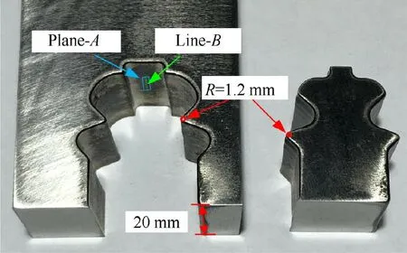
Fig.19 Machined mortise and tenon samples.
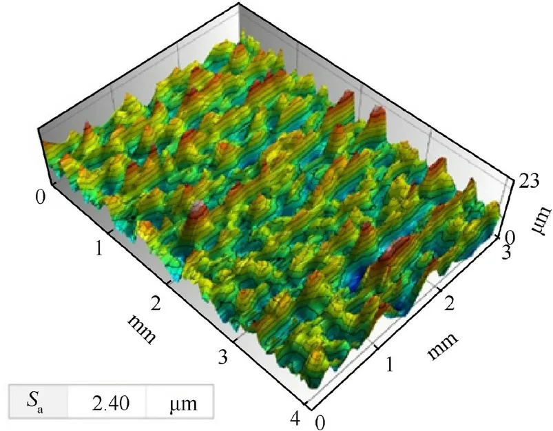
Fig.20 Surface morphology of Plane-A.
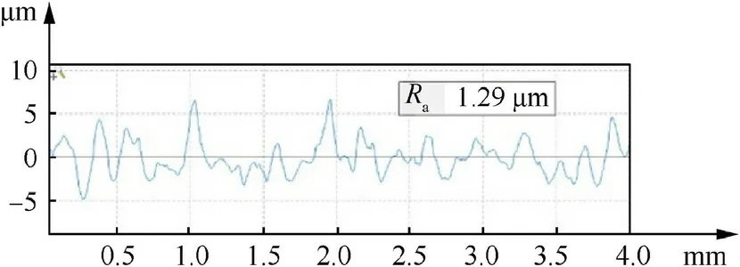
Fig.21 Profile of Line-B.
5.Conclusions
To realize high-efficiency,high-quality machining of mortisetenon joint structures,this paper has described an electrochemical cutting process using a rotary tube electrode with helically distributed jet-flow holes.A series of simulations and experimental investigations were carried out,and the main conclusions can be summarized as follows:
(1) The rotational speed of the tube electrode determines the direct spraying times of the high-speed electrolyte ejected from the jet-flow holes onto the machining area.A higher rotational speed of the tube electrode leads to faster removal of electrolytic products and a larger slit width.
(2) The electrolyte pressure determines the flow rate of the electrolyte in the machining gap and the flow velocity of the electrolyte ejected from the jet-flow holes.An increase in electrolyte pressure increases the flow rate and flow velocity of electrolyte in the machining gap,and increases the width of the slit.
(3) A lower pulse voltage,smaller pulse duty ratio,and greater pulse frequency are beneficial to improving the accuracy of electrochemical cutting.
(4) The standard deviation and roughness increase when the slit width is too large,the result of some deterioration of the flow field and electric field distribution in the machined slit caused by excessive electrolytic products.
(5) Mortise and tenon samples were successfully machined on 20-mm-thick Inconel 718 alloy at a feeding rate of 5 μm/s using the optimal machining parameters.
The authors declare that they have no known competing financial interests or personal relationships that could have appeared to influence the work reported in this paper.
This project was supported by the National Natural Science Foundation of China (No.91960204),the Natural Science Foundation of Jiangsu Province(No.BK20191279),the Aeronautical Science Foundation of China (No.201907052002),and the National Natural Science Foundation of China for Creative Research Groups(No.51921003).The authors would also like to thank the editors and referees for their insightful comments and suggestions.
 Chinese Journal of Aeronautics2022年2期
- Chinese Journal of Aeronautics的其它文章
- Pressure-induced instability and its coupled aeroelasticity of inflated pillow
- Adjoint boundary sensitivity method to assess the effect of nonuniform boundary conditions
- Transit time difference and equal or non-equal transit time theory for airfoils with lift
- A boundary surrogate model for micro/nano grooved surface structure applied in turbulence flow control over airfoil
- Nonlinear uncertainty quantification of the impact of geometric variability on compressor performance using an adjoint method
- High precision and efficiency robotic milling of complex parts:Challenges,approaches and trends
