Surface morphology characterization of unidirectional carbon fibre reinforced plastic machined by peripheral milling
Chongyan CAI,Jiaqiang DANG,Qinglong AN ,Weiwei MING,Ming CHEN
School of Mechanical Engineering, Shanghai Jiao Tong University, Shanghai 200240, China
KEYWORDS Carbon fibre reinforced plastic (CFRP);Surface characterization;Surface morphology;Surface roughness;Surface texture
Abstract This paper aims to characterise surface morphology and 3D roughness parameters of unidirectional carbon fibre reinforced plastic(UD-CFRP)milled at 0°,45°,90°,and 135°fibre orientation angles (FOAs).Side milling experiments are conducted on UD-CFRP laminates.Surface damage forms and texture direction of milled surface are analysed.Spatial frequency of defects on CFRP surface is quantitatively determined using radially averaged 2D PSD.The kinematicdynamic surface topography is reconstructed considering feed,runout and vibration,then the ideal roughness parameters, Sa, Sq, Ssk,and Sku are calculated and compared with the measured ones,finally the material factor-induced roughness components are quantified.Results show that CFRP surface has no regular feed marks.The frequency of fibre breakage or surface defects is greater than tooth passing frequency.FOAs sorted by their average Sa in descending order is 135°>90°>45°>0°,where surface defects contribute 93.9%,77.1%,73.2%,72.2% of the total roughness respectively,which suggests that surface defects show a more important role than tool kinematics and vibration in formation of milled surface.The negative Skewness(Ssk <0)and high Kurtosis (Sku=4.0-11.5) of milled surface signify porosity and the presence of many anomalous deep valleys in milled surface,respectively.
1.Introduction
With their low density,high specific strength,high temperature and corrosion resistance,carbon fibre reinforced plastic(CFRP) is widely used in commercial aircrafts and cars in order to significantly reduce the weight of aircrafts and cars without losing strength.CFRP often requires secondary processing,such as drilling and trimming.The purpose of drilling is to meet the need for a large number of assembly connection holes.The purpose of trimming is to cut large CFRP components or to obtain sides with sufficient shape accuracy and free of burrs.Abrasive water jet (AWJ) machining and milling are two common methods of edge-trimming CFRP.Milling operation is the main way of machining complex structural parts such as cavity,blade and aircraft skin on aerospace vehicle.Although AWJ minimises tool wear and produces little residual stress and workpiece reaction forces,AWJ equipment is expensive and it is difficult to control that the jet does not penetrate.AWJ is mainly used in locations where penetration work is required.CFRP is a typically hard-to-machine material,as evidenced by the fact that friction between the protruding fibres and the tool’s flank face tends to induce abrasive wearand that the machined top layer is prone to delamination.The surface finish of a part affects its frictional properties,wear resistance,corrosion resistance and fatigue breakage resistance.Therefore,it is of great importance to quantitatively characterise the surface morphology of CFRP after economical and efficient milling operation.
CFRP exhibits strong anisotropy and many scholars have made extensive studies on the material removal mechanism during orthogonal cutting of CFRP.Wang and Zhangfound that severe springback occurred on the material surface after CFRP cutting,due to the elastic bending of the high strength carbon fibres.Li et al.proposed a multi-pass cutting strategy to replace single-pass cutting to improve surface integrity of CFRP,and based on their method,fibre pull-out damage can be reduced by 63%.The discrete element model developed by Iliescu et al.can well simulate the material removal process during orthogonal cutting of CFRP captured by a highspeed camera.An et al.analysed the stress state of carbon fibre-resin microelements and studied the fracture mechanism of carbon fibres and its effect on surface defect formation.Voss et al.analysed in detail the material fracture mechanism at the tool rake face,blunt circle edge position,and the tool flank face in contact with CFRP with various FOAs.Xu and Zhangproposed a numerical method to characterise the quality of CFRP cutting surfaces:a finite element model of CFRP cutting was developed and the nodal coordinates were imported into MATLAB after the simulation for subsequent calculation of surface roughness parameters.


During the milling process,tool runout and vibration affect the ideal trochoid trajectory of the tool,which consequently affect surface topography and area surface roughness parameters.For the milling of metallic materials,the milled surface pattern reflects the relative motion of tool and workpiece,in other words,the geometric-kinematic factors dominate surface formation process.However,for the milling of anisotropic CFRP,the cutting mechanism differs from that of metallic materials,and surface defects(material factors)may also influence the surface topography and area roughness parameters to a large extent.There is little research on the quantitative determination of the material factor induced roughness components during CFRP milling.
Therefore,this study reconstructs the ideal surface topography considering tool runout and vibration and calculates the theoretical 3D surface roughness parameters.The theoretical 3D surface roughness parameters are then compared with the measured ones to quantitatively determine the contribution of material factors to the total roughness.The,parameters,surface defects,surface texture direction,and radially averaged 2D PSD of CFRP surface are also analysed.
2.Material and method
2.1.Experiment procedure
Fig.1 shows the experiment set-up.Side milling experiments are performed on a DMU 70 V machining centre.The use of flood cooling during cutting of CFRP will cause hygrothermal aging.It has been demonstrated that the use of MQL can reduce cutting forces and improve surface integrity during machining of metallic materials.However,in the case of composites,their porous nature causes them to rapidly absorb lubricating droplets,so MQL alone is not an effective solution for improving the machinability of CFRP.Therefore,in this study,dry milling condition is adopted.Workpiece is T300/QY8911 UD-CFRP laminate with 40 plies,thickness being 5 mm,and thickness of each ply being 0.125 mm.The average diameter of the carbon fibres is about 7 μm.The milling cutter is a carbide end mill with 5 flutes and a diameter of 10 mm.Modal parameters of the tool are obtained by impact hammer experiments.Modal parameters in feed direction:natural frequency ω=2255.5 Hz,damping ratio ζ=2.24%,stiffness k=1.8×10N/m.Modal parameters in perpendicular feed direction:ω=1573.6 Hz,ζ=2.31%, k=2.0×10N/m.Tool runout parameters are measured using dial gauge.Eccentric distance is ρ=8 μm,eccentric direction is λ=30°.Milling forces are measured using Kistler 9272 dynamometer with a sampling frequency of 80 kHz.The operation parameters are summarized in Table 1.

Table 1 Milling parameters.
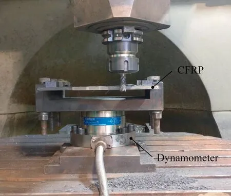
Fig.1 Experiment set up.
The cutting speed is kept at a constant value of=20 m/min.The reason for the low cutting speed is to reduce the effect of tool wear on surface topography.The radial depth of cut and axial depth of cut are also kept constant at=0.5 mm and=5 mm respectively.The feed per toothtakes 5 levels.Experiments are carried out at FOAs of 0°,45°,90°and 135°.The FOA is defined as shown in Fig.2.After the experiment,the machined surfaces are measured using a laser confocal microscope(Model:Smartproof 5,Carl Zeiss Microscopy GmbH) equipped with Mountains 8 software.
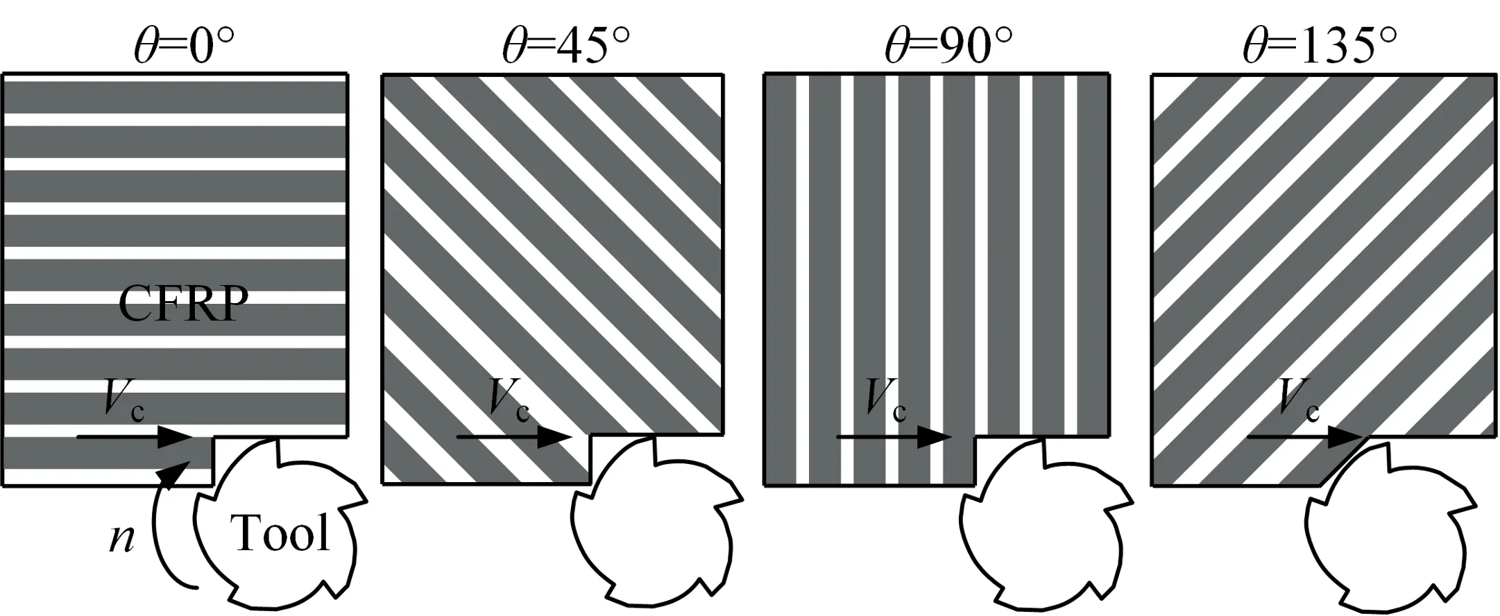
Fig.2 Definition of fibre orientation angle.
2.2.Method:Determining the contribution of material-induced surface roughness
During milling of CFRP,the milled surface topography depends on tool trajectory and machined surface defects (material factor).Tool trajectory is influenced by tool runout and tool vibration.The ideal surface topography and 3D surface roughness due to tool runout and vibration (ideal roughness)can be predicted by theoretical model.The material-induced roughness component is determined by subtracting the actual measured roughness from the ideal roughness.Then,by subtracting the ideal roughness from the actual measured roughness,the roughness caused by surface defects can be determined.
Fig.3 is a schematic diagram of milling process,the trajectory of end mill is a trochoid,which can be expressed by the following equation:

where,is nominal cutter radius.ω is angular velocity of the tool rotation.is time.φis pitch angle of end mill,φ=2π/,is number of cutter tooth.β is tool helix angle.is the index of tooth,is the index of axial differential element of tool,is the index of angular differential element of tool rotation.zis the axial height ofth axial differential element of end mill.is feed speed,=××,is feed per tooth,is spindle speed.
During side milling,tool runout is inevitable.Fig.3 depicts the principle of tool runout.Tool runout results in different equivalent rotational radii of different axial differential elements or different cutter teeth.Considering tool runout,the equivalent radius of tool rotation as a function of axial height and tooth index is given by Kline and DeVor:where,ρ(μm)is the eccentricity distance and λ(°)is the direction of eccentricity.
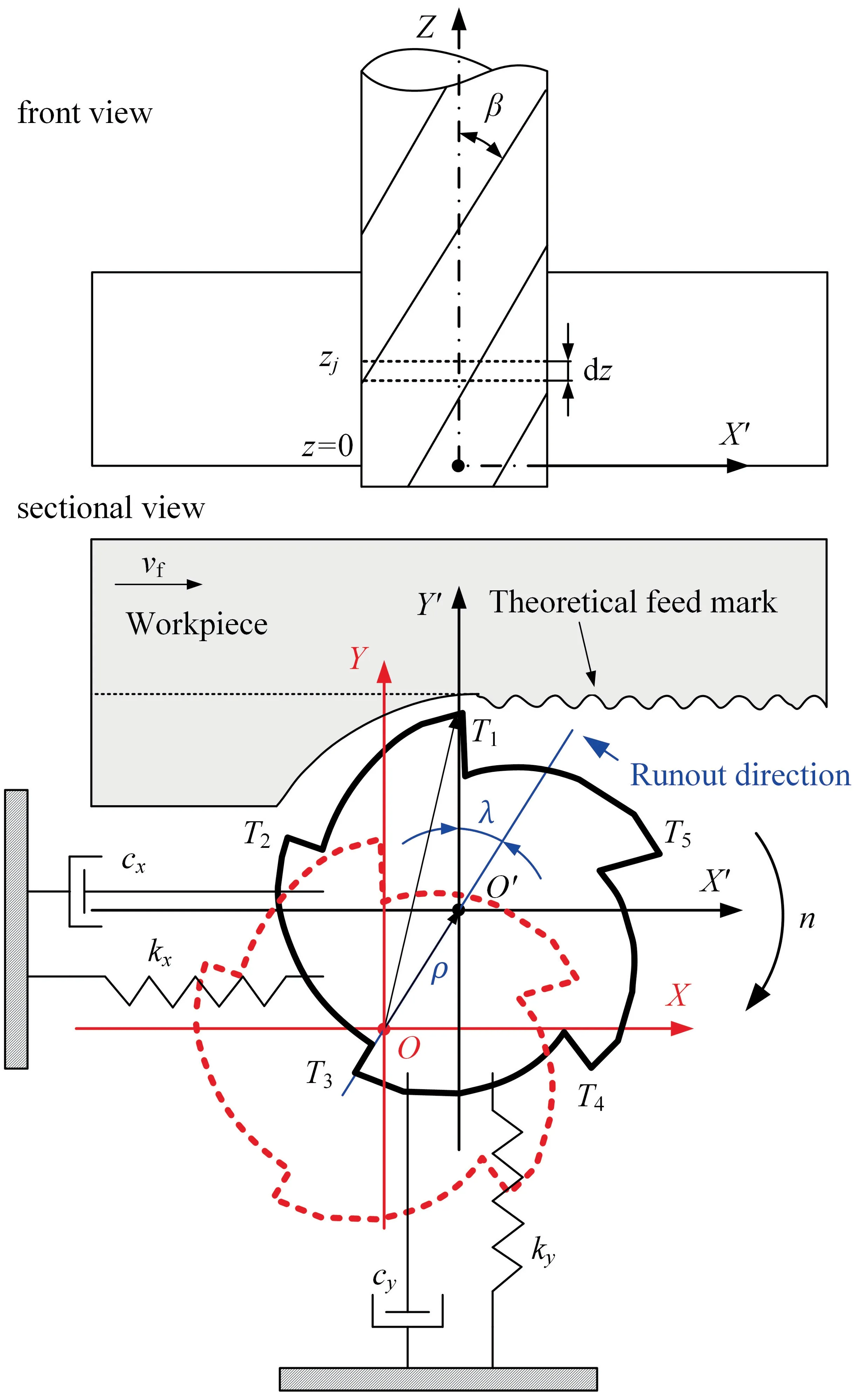
Fig.3 Schematic diagram of side milling process.

The end mill can be considered as a two-degree-of-freedom mass-damped-spring system,then the dynamic vibrational displacements in feed directionand perpendicular feed directioncan be obtained by solving the following secondorder inhomogeneous linear differential equations:

where,ωand ωare natural frequency,ζand ζare damping ratio, kand kare modal stiffness. F()and F()are the instantaneous milling forces in the feed direction and perpendicular feed direction respectively and can be experimentally measured.
Therefore,considering tool runout,Eq.(2) is substituted into Eq.(1);considering tool vibration,the vibration displacementsandderived from Eq.(3) are substituted into Eq.(1);then the resultant trajectory of tool tip is determined:

For a given axial height z,the highest position of all trajectories of all cutter teeth relative to the workpiece will create the 2D surface profile.By repeating this operation for all axial heights,the 3D surface topography can then be reconstructed,which is referred to as the kinematic-dynamic surface topography.As an example,Fig.4 presents the kinematic-dynamic surface topography when FOA θ=0°,=0.13 mm.
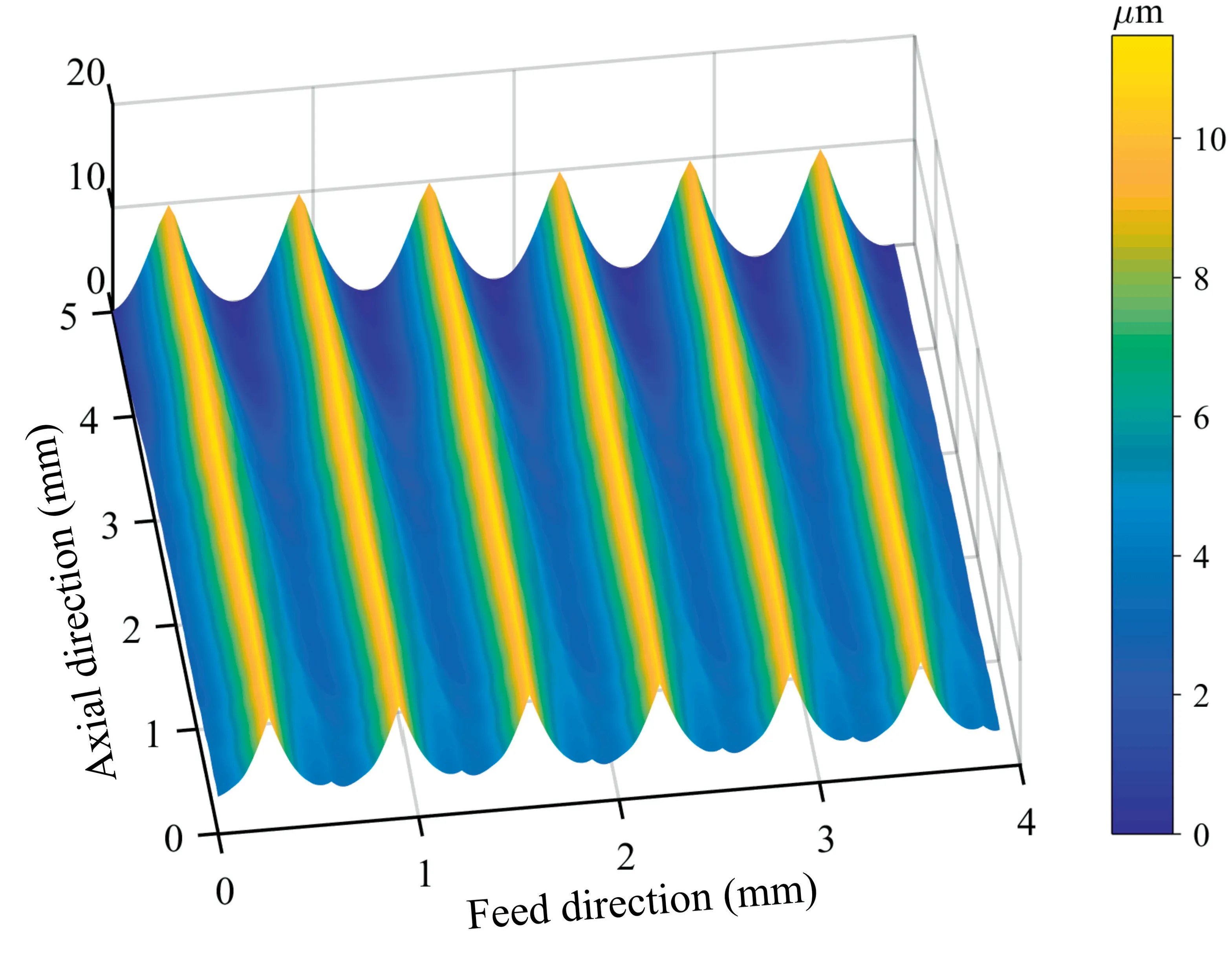
Fig.4 Simulated surface considering tool runout and vibration (ft=0.13 mm,0° fibre orientation angle).
Once the kinematic-dynamic 3D surface topography has been obtained,then the theoretical 3D surface roughness parameters can be calculated.The arithmetic mean heightof a surface,(,),within a sampling area,,is given by Eq.(5);the root mean square height of a surface,,is given by Eq.(6);the Skewness of a surface,,is given by Eq.(7);the Kurtosis of a surface,,is given by Eq.(8).

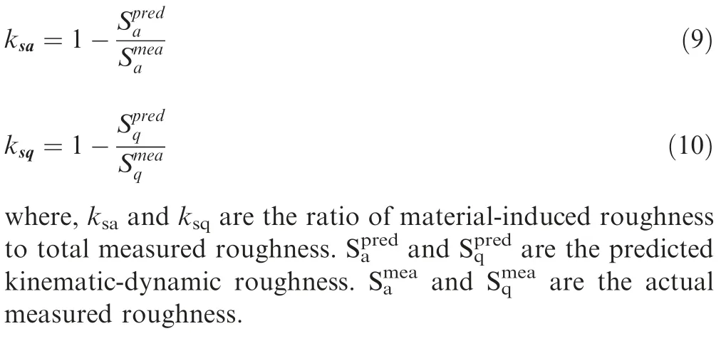
In order to quantify the ratio of roughness contributed by material factors to the actual measured roughness,the ratiosandare proposed,as expressed in the following equations:
3.Results and discussion
3.1.Surface topography
Fig.5 presents the CFRP surface topography at FOA θ=0°when feed per tooth=0.13 mm.At 0° FOA,the cutting speed/tool advance is parallel to the fibre arrangement direction.The main mechanism of machined surface formation is shear debonding of the fibre-resin interface with the advance of cutter.Long fibres arranged parallel to the feed direction are exposed to the machined surface,some of which shear off under the squeezing action of cutting edge,forming fine short fibres.Some of the fibres are debonded from the resin connection and the fibres pull out,leaving long pores on the surface parallel to the feed direction.The resin is plastically deformed or torn by the ploughing action of tool flank face and the residual resin protrudes on the milled CFRP surface.Because there are no cracks that extend into the material,the milled surface of CFRP with θ=0° is generally flat and smooth.
It is noted that there are very slight feed marks on the machined surface (see the relatively white vertical lines with arrows pointing in Fig.5(a)).Due to tool runout,the distance between two adjacent feed marks is=0.5 mm,approximately equal to=0.65 mm,i.e.,tool feed length in one spindle rotation cycle.However,the feed tool marks are very insignificant,suggesting that the machined surface formation depends primarily on the material removal mechanism rather than on the tool trajectory.
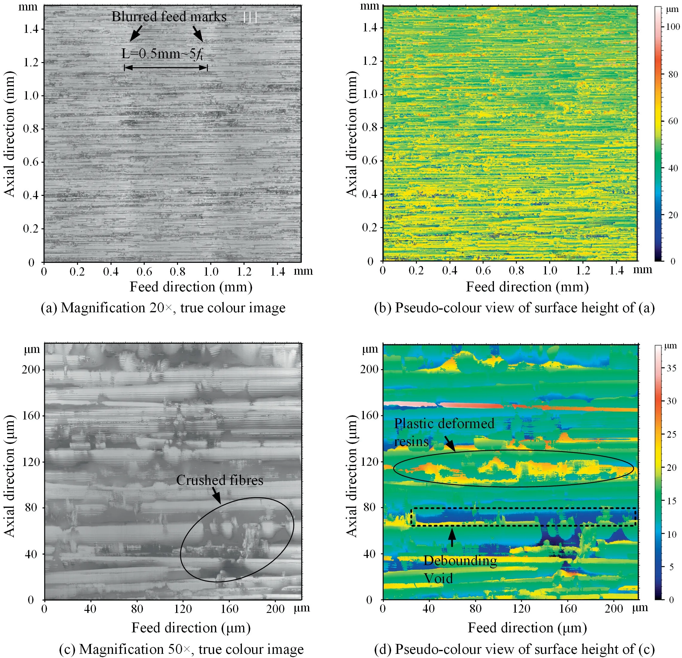
Fig.5 CFRP surface topography at FOA θ=0° when ft=0.13 mm.
Fig.6 presents the CFRP surface topography at FOA θ=45° when=0.13 mm.No feed marks are visible on the machined surface.At 45° FOA,the material removal process undergoes fibre breakage located below the cutting edge and subsequent shearing at the resin-fibre interface towards the free surface to be cut.As the fracture of carbon fibres occurs below the cutting plane,the machined surface is left with dense,random small craters and the surface quality is worse relative to that at 0° FOA.In addition,because of the severe rebound of the machined surface,the carbon fibres and resins rub and plough violently against the tool flank face,so there are many residual plastically deformed resins on the milled surface.
Fig.7 presents the CFRP surface topography at FOA θ=90° when=0.13 mm.For CFRP with 90° FOA,the material removal mechanism is shear fracture of carbon fibres under the squeezing action of the cutting edge.The protruding rounded carbon fibres are clearly visible on the machined surface.In addition,cracks may open vertically downwards along the fibre-substrate interface due to tool extrusion,resulting in random fracture craters on the machined surface,which can deteriorate the surface quality.For example,the depth of crater in Fig.7 (d) is 25 μm.
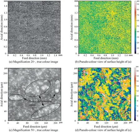
Fig.6 CFRP surface topography at FOA θ=45° when ft=0.13 mm.
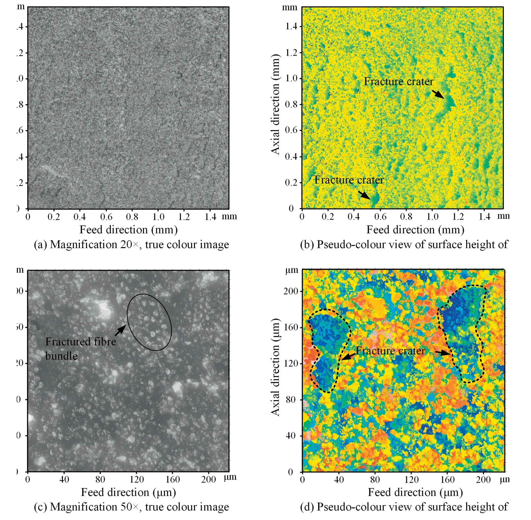
Fig.7 CFRP surface topography at FOA θ=90° when ft=0.13 mm.
Fig.8 presents the CFRP surface topography at FOA θ=135° when=0.13 mm.Once again,the machined surface has no feed patterns,but rather many randomly distributed massive fracture pits and corresponding fracture surfaces.The pits seriously deteriorate the surface quality.The pits are formed when the fibre bundle bends under the pushing action of tool,then the crack at fibre-resin interface extends diagonally into the material,then the fibre bundle breaks under the continued pushing action of tool,resulting in many pits remaining on the milled surface.For example,the depth of pit in Fig.8(d)is 120 μm,much greater than that in the case of 90° FOA (see Fig.7(d)).Unlike the case of 45°FOA where fibres in front of the tool are well supported,the surface damage of CFRP at 135°FOA is more severe than that at 45° FOA.Henerichs et al.,Wang and Zhangalso observe fracture pits on CFRP surface in orthotropic cutting at 135°FOA;the pits are regularly distributed in a jagged pattern and the angle between the slope of pits and the cutting direction is exactly 135°,demonstrating the extension of cracks along the fibre-resin interface.However,in our study,the pits on the milled surface do not show a uniform and regular jagged shape,but rather a randomness,which is accredit to the machining method (milling or orthogonal cutting).
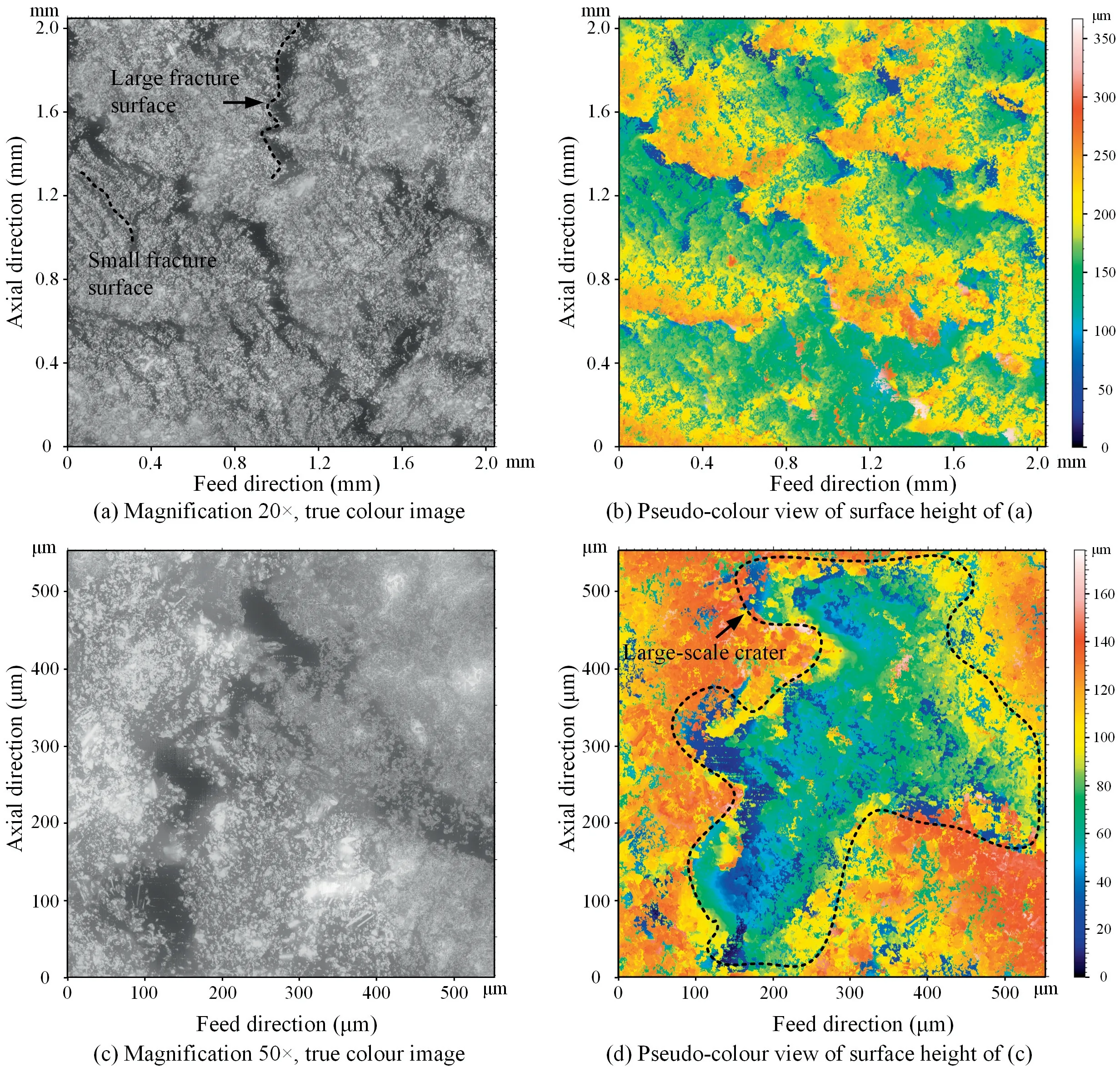
Fig.8 CFRP surface topography at FOA θ=135° when ft=0.13 mm.
3.2.Surface texture direction
As an example,Fig.9 depicts the polar spectrum of surface texture direction at 0°,45°,90°,and 135° FOAs when=0.13 mm.For the 0°FOA,the CFRP surface exhibits anisotropy with a 0° main texture direction,representing either the feed direction or the fibre alignment direction.The energy at the 90° position in the angular spectrum is relatively low as the feed marks are very insignificant.For CFRP with 45°,90°and 135°FOAs,the surface texture is homogeneous due to the random distribution of fracture pits on the surface.The angular spectrum of surface texture direction is indicative of the surface characteristics.For example,for the angular spectrum at 90°FOA,the 1st principal direction of surface texture is 90°,which is in close agreement with the direction of brittle fracture crater in Fig.7(b).Notice that for CFRP surface with 45°and 135° FOAs,their angular spectrums of texture direction show stronger energy at around 45° and 135° than at other angles,due to the expansion of cracks at the resin-fibre interface along these two directions and fibre fracture perpendicular to these two directions.
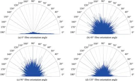
Fig.9 Angular spectrum showing surface texture direction.
The surface texture direction approach allows the characterisation of the isotropy of machined surface,the quantitative determination of main texture direction and the characterisation of defects on the machined surface.This method has also been applied to assess the anisotropic behaviour of metal surfaces after ball burnishing.Nevertheless,this method does not allow for the quantitative determination of information on the size of surface defects,i.e.,the fundamental wavelength of surface defects and its corresponding power spectral density.To cope with this challenge,the method of radially averaged 2D power spectrum density can be used to quantify information about surface defects in the spatial frequency domain.
3.3.Radially averaged 2D power spectrum density of CFRP surface
As an example,Fig.10 presents the radially averaged 2D power spectrum density (PSD) of CFRP surface at various FOAs after milling at=0.13 mm.Theoretically,when only the feed motion is considered,the spacing between adjacent peaks or valleys of the surface profile is,so the main wavelength of spectrum is.Due to tool runout,the spacing between adjacent peaks of surface profile lies in the interval[,].When considering tool vibration,the surface profile will have a period greater than,depending on the chattering frequency.Therefore,when all kinematic-dynamic factors,i.e.,runout and vibration,are considered,then the principal wavelength of surface’s spectrum will certainly be greater than.However,the principal wavelengths of actual measured surfaces are all much smaller thanregardless of FOAs.A similar phenomenon was found by Nieslony et al.during the turning of 41Cr4 steel with self-propelled rotary tool.The fundamental wavelengths of PSD on CFRP surface with 0°,45°,90°,135°FOAs are 0.024,0.026,0.035,0.020 mm,respectively.This indicates that the frequency of surface defects is greater than the spatial frequency of feed grooves,in other words,defects related to material removal mechanism,e.g.,fibre breakage,fibre debonding,resin ploughing,etc.,are more important than tool kinematics and dynamics concerning milled surface formation.The spectra of CFRP surfaces with 0°,45° and 90° FOAs have multiple characteristic peaks,indicating the diversity of defect forms and sizes (see Fig.5,Fig.6,Fig.7).For the spectrum of milled surface with 135° FOA,the power spectrum density at the main wavelength is 4×10μm,which is almost 90 times higher than that for 0°,45° and 90° FOAs,suggesting that the size of fracture crater is larger and the surface finish is rougher for 135° FOA,as confirmed by surface morphology images (Fig.5-8).
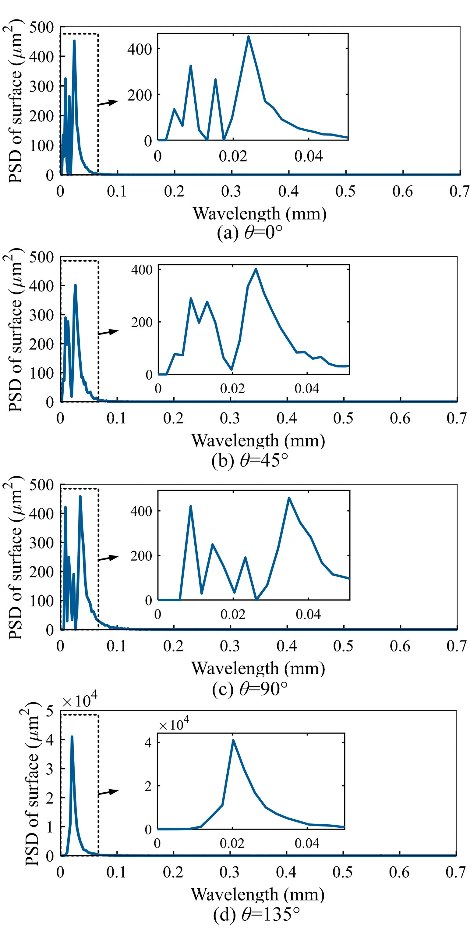
Fig.10 Radially averaged 2D power spectrum of milled CFRP surface at various FOAs.
3.4.Surface roughness parameters
Fig.11 presents the 3D surface roughnessof CFRP surface after milling at various FOAs and feed rates.The descending order of FOA based on the average value ofobtained for all examined feed rates at each FOA is 135°>90°>45°>0°,with values corresponding to 36.2 μm >9.74 μm >9.67 μm >7.81 μm.The averageat 135° FOA is 28 times greater than that at 0° FOA.Despite the above ranking of the mean values of,the averageat 90°,45° and 0° FOAs differs very little,which is only 1.93 μm.
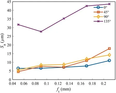
Fig.11 Sa obtained at various feed rates and FOAs.
Regarding the relationship betweenand feed per tooth,as expected,tends to be positively correlated with.This is because,from the point of view of tool kinematics,both the width and height of the residual feed marks increase with increasing;from the point of view of machining dynamics,the intensity of forced vibration increases with increasing chip load.However,some anomalies are noted,such as the case of=0.10 mm,θ=135°.This is attributed to random surface defects induced by material fracture.
The ratio of material-induced roughnessto total roughness,is shown in Fig.12.The descending order of FOA based on the average value ofobtained for all examined feed rates at each FOA is 135°>90°>45°>0°,with values corresponding to:93.9%>77.1%>73.2%>72.2%.This reflects the anisotropy of CFRP.Once again,the difference between the mean values ofat 90°,45° and 0° FOAs is very small,only 4.9%.The contribution of surface defects to the total roughness is greater than 60% for all analysed feeds and FOAs,suggesting that considering the tool trajectory alone does not accurately predict CFRP milled surface roughness,and that the material removal mechanism shows a more important role than tool kinematics regarding the surface formation process in milling of CFRP.
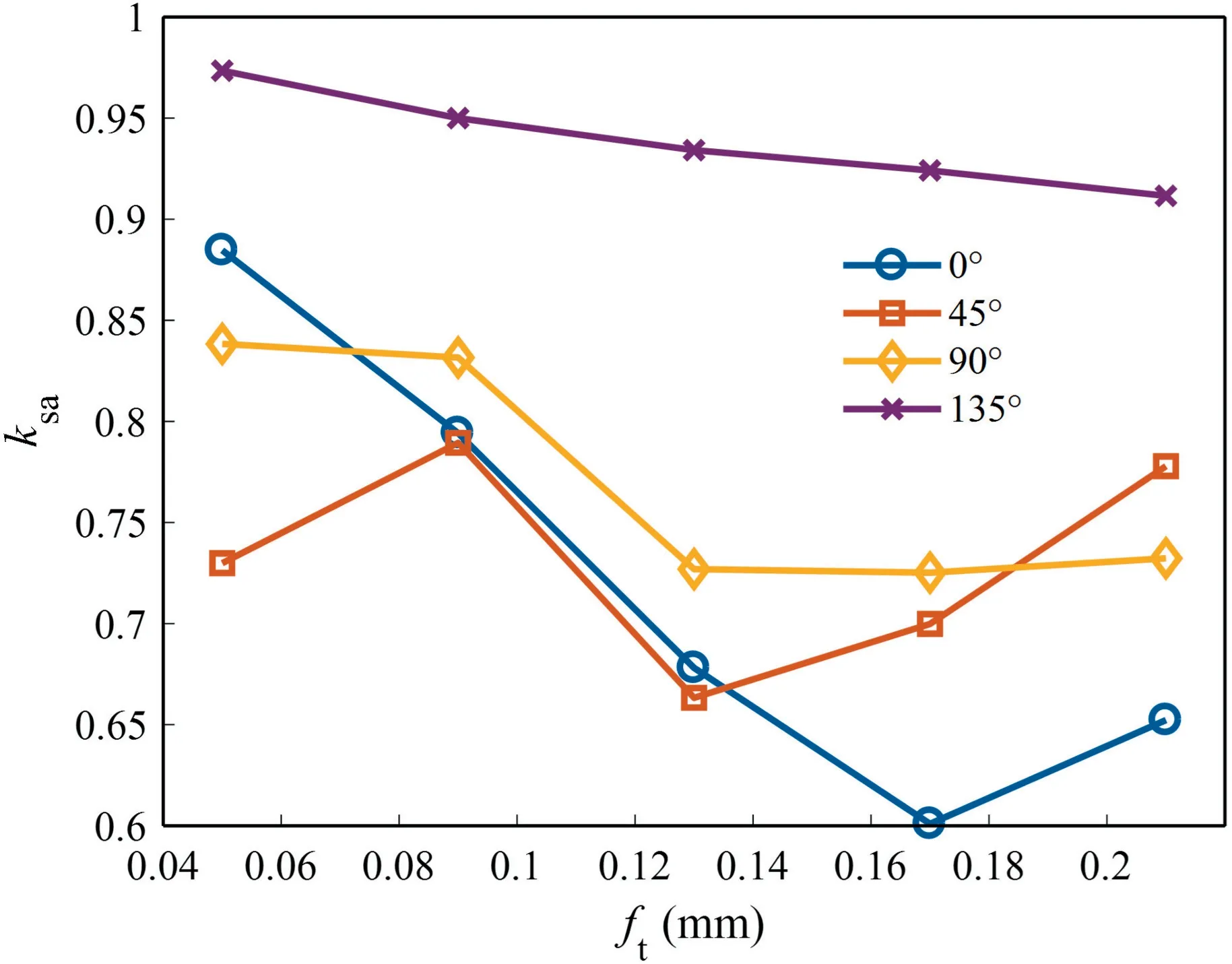
Fig.12 Ratio of material-induced roughness Sa to total roughness, ksa.
Fig.13 shows thevalues for different FOAs and feed rates.Fig.14 shows the ratio of material-induced roughnessto total roughness,.The average values ofwith all examined feed rates at 135°,90°,45° and 0° FOAs are 49.9 μm,15.7 μm,15.0 μm and 12.1 μm respectively.The trend ofwith FOA is consistent with the trend ofwith FOA.Numerically,thevalue is slightly larger than thevalue,which is due to the different defining equations of the two.The average values offor 135°,90°,45° and 0° FOAs are 94.7%,82.5%,79.5%and 78.7%respectively,which are close to thevalues.Values ofgreater than 75% once again indicate the dominant role of surface defect inducing factors such as carbon fracture and crack extension in the generation of CFRP milled surface topography.
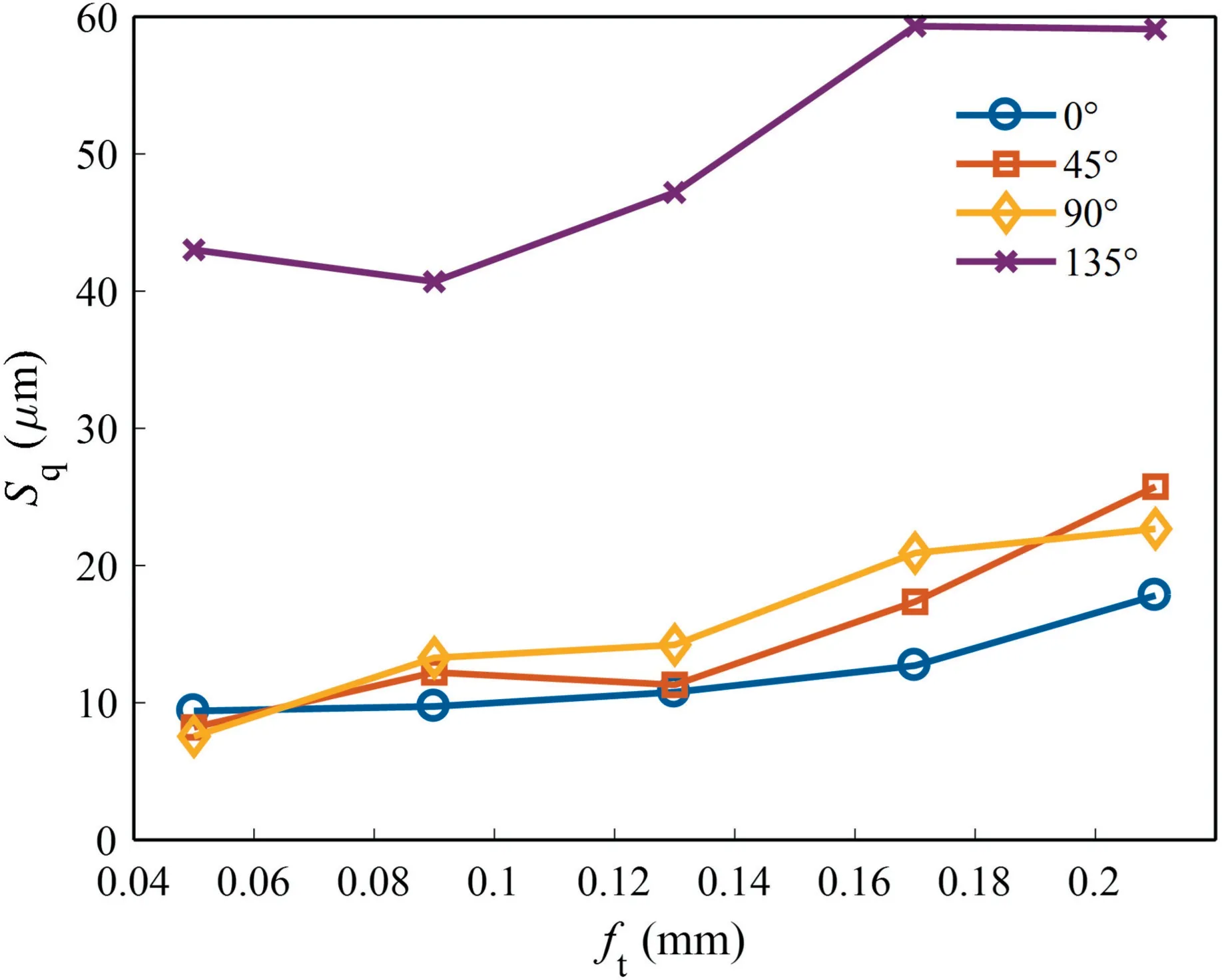
Fig.13 Sq obtained at various feed rates and FOAs.
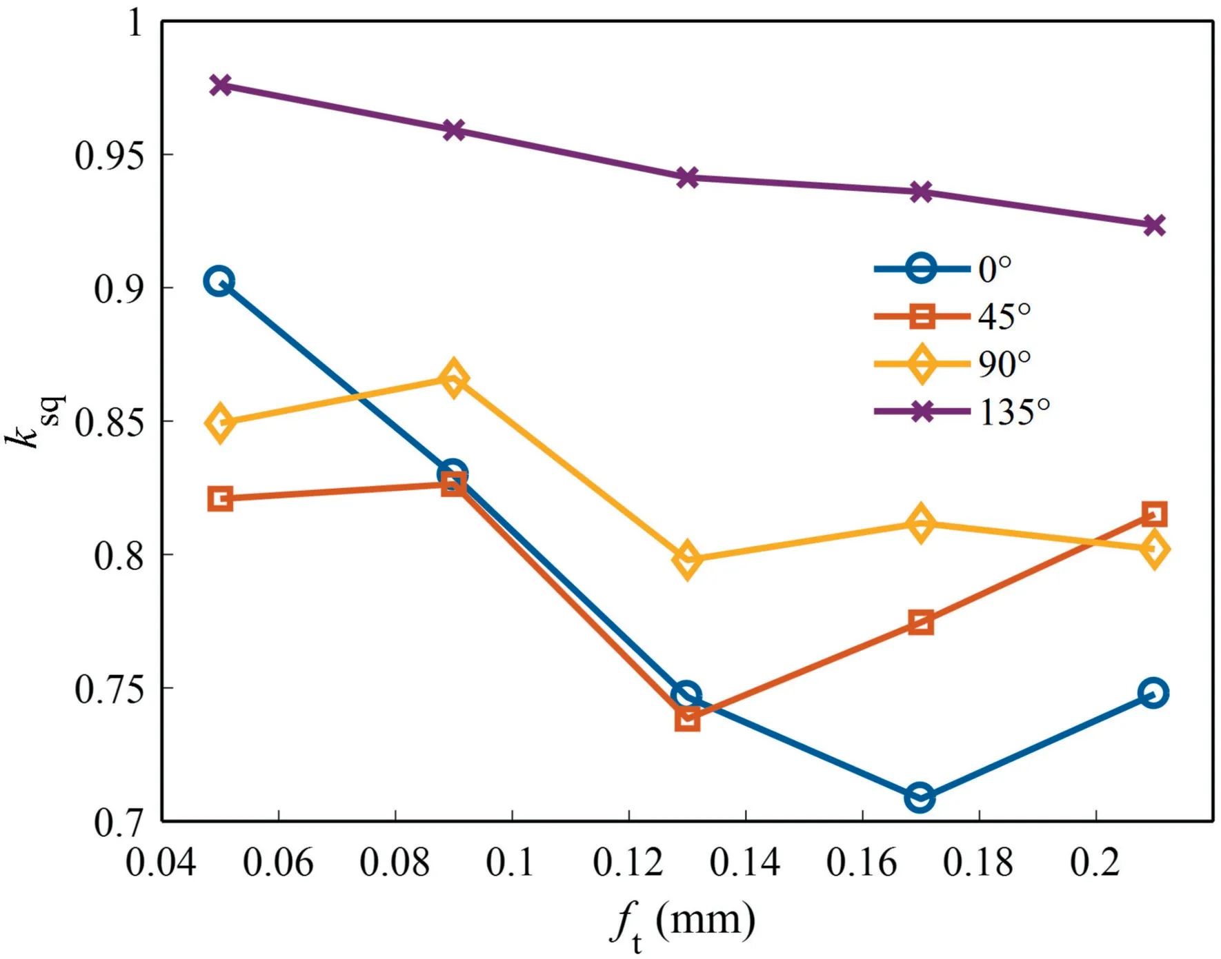
Fig.14 Ratio of material-induced roughness Sq to total roughness, ksq.


Fig.15 Schematic representation of surface profile with Ssk <0, Ssk >0, Sku >3 or Sku <3.28

The variation of Kurtosis () of the CFRP surface with feed per toothat different FOAs is shown in Fig.17.values are greater than 3,between 4.0 and 11.5,regardless of FOA and feed per tooth,which means that the CFRP surface after milling has many abnormal spikes and deep valleys.The predictedvalues by considering only tool trajectory lie in the interval [2.0,3.5],which is similar to thevalues for machined surfaces of metallic materials.For example,Krolczyk et al.found=[2.25,4.00] for turned stainless steel surfaces;Nieslony et al.found=[1.7,2.8] for turned hardened steel surface;Swiradfound thatvalue of the burnished steel surface was nearly equal to 3,reflecting the random nature.The highvalues of CFRP surfaces after milling further indicate that the cutting mechanism of CFRP differs significantly from that of metallic materials,that the quality of CFRP milled surfaces is poorer relative to metals,and that material factors dominate the surface formation process in milling CFRP.
As can be seen from Fig.16 and Fig.17,has no significant effect onand,which show a certain randomness.The average value ofandwithin all examined feeds at each FOA is shown in Fig.18.For,the absolute values of averages ofat different FOAs are 90°>0°>135°>45° in descending order,with their values lying in interval [-0.490,-1.673].The 90°FOA has the smallestvalue,-1.673,indicating the greatest degree of asymmetry and the greatest porosity in its surface.This is due to the protrusion of the carbon fibres and the vertical extension of the cracks towards the interior of material.For,the averages ofat different FOAs are 90°>0°>45°>135° in descending order,with their values corresponding to 8.41 >8.01 >7.46 >4.77 respectively.This also indicates that the 90°FOA has the spikiest surface,which is caused by the protrusion of fractured carbon fibres towards the machined surface.In addition,thevalue for 135°FOA is closest to 3,indicating that the surface is closest to a Gaussian random distribution,which is related to the massive random fracture craters in the milled surface (see Fig.8).
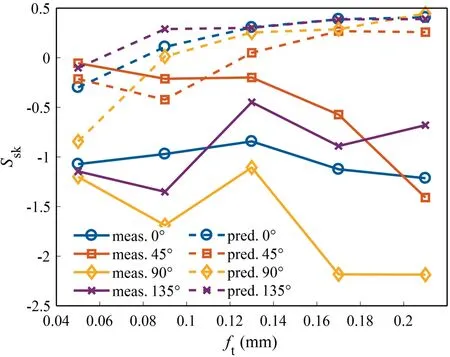
Fig.16 Ssk obtained at various feed rates and FOAs.
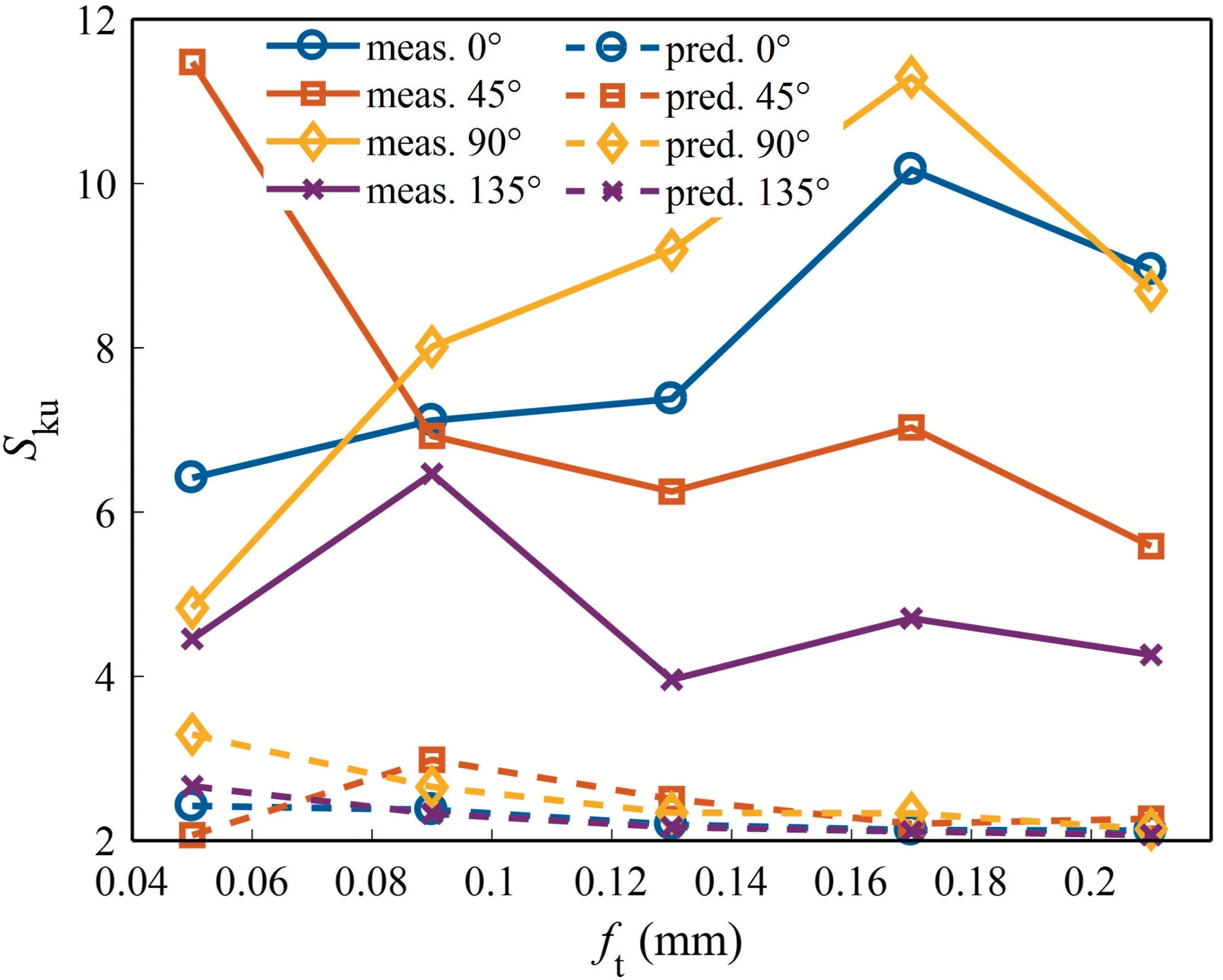
Fig.17 Sku obtained at various feed rates and FOAs.
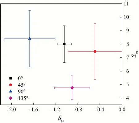
Fig.18 Average values of Ssk and Sku at various FOA.
4.Conclusions
This paper focuses on the characterization of surface morphology of UD-CFRP after milling at different FOAs.For this purpose,milled surface morphology,surface texture direction,radially averaged 2D PSD of CFRP surface,and 3D roughness parameters,,andare investigated.Roughness components due to surface defects are quantified.The conclusions are as follows:
(1) Surface defects at θ=0° are fibre breakage,resin ploughing and fibre-resin debonding voids.Surface defects at θ=45° are random small pits and residual plastic deformed resin.Surface defects at θ=90° are fibre protrusions,vertical cracks and random small fracture pits.Surface defects at θ=135°are large-scale fracture pits.No visible feed marks are on the milled surface regardless of θ.
(2) Milled surface at θ=0° exhibits anisotropy with main texture direction being fibre alignment direction.Milled surfaces at θ=0°,45° and 135° are isotropy due to the random distribution of fracture pits on the machined surface.
(3) The fundamental wavelength of 2D PSD of CFRP surface after milling is less thanregardless of FOA,showing an independence from tool kinematics,implying that the frequency of fibre breakage or other surface defects is greater than the tooth passing frequency.
(4) The FOA sorted by its average value ofin descending order is 135°>90°>45°>0°,with values corresponding to 36.2 μm >9.74 μm >9.67 μm >7.81 μm.The trend ofwith θ oris consistent with.
(5) The ratio of material-induced roughness to total roughness,and,both exhibits statistically insignificant correlation with,suggesting the random nature of fibre breakage and defect formation during milling of CFRP.andare in the interval[72%,82%],implying that surface defect rather than tool kinematics or dynamics dominates the milled surface formation process.
(6) CFRP milled surfaces have a porous nature (<0).High kurtosis (=4.0-11.5) of CFRP surfaces implies the presence of many abnormally deep valleys.90° FOA has the spikiest surface due to protrusion of carbon fibres and extension of vertical cracks.Milled surface at θ=135°is closest to Gaussian random distri
bution due to presence of massive random fracture craters.-parameters are an effective tool for detecting irregularities in milled CFRP surface.
This study contributes to the understanding of the characteristics of CFRP milled surface topography,and also provides some guidance to future scholars in developing predictive models for 3D surface roughness in CFRP milling operation.In the future studies,the effect of vibration assisted cutting and cryogenic cooling techniques on surface integrity of CFRP surface can be explored.
The authors declare that they have no known competing financial interests or personal relationships that could have appeared to influence the work reported in this paper.
This study was supported by the National Key R&D Program of China (No.2020YFB2010600).
 Chinese Journal of Aeronautics2022年2期
- Chinese Journal of Aeronautics的其它文章
- Pressure-induced instability and its coupled aeroelasticity of inflated pillow
- Adjoint boundary sensitivity method to assess the effect of nonuniform boundary conditions
- Transit time difference and equal or non-equal transit time theory for airfoils with lift
- A boundary surrogate model for micro/nano grooved surface structure applied in turbulence flow control over airfoil
- Nonlinear uncertainty quantification of the impact of geometric variability on compressor performance using an adjoint method
- High precision and efficiency robotic milling of complex parts:Challenges,approaches and trends
