A novel approach to the attitude stabilization structure for ducted-fan operative aerial robots:Finding improvements for modeling error and strong external transient disturbance
Wei FAN ,Bin XU ,Chngle XIANG ,Yibo ZHANG,b ,Hiyng YANG
a School of Mechanical Engineering,Beijing Institute of Technology,Beijing 100081,China
b Beijing Institute of Technology Chongqing Innovation Center,Chongqing 401135,China
c School of Automation,Beijing Institute of Technology,Beijing 100081,China
KEYWORDS Adaptive control;Disturbance rejection;Ducted-fan aircraft;Modeling error;Stability augmentation systems
Abstract This research concerns a novel attitude stabilization structure for a ducted-fan aerial robot to work against modeling error and strong external transient disturbance,and it focuses on two main control targets:modeling error compensation,and the improvement of disturbance resistance along the rolling channel.For the first research objective,we proposed an adaptive nominal controller with the reconfigurable control law design based on the estimation of the modeling error found in the closed-loop.Results of simulations and corresponding flight tests verified that the proposed adaptive control structure is robust against both constant and time-varying modeling error.For the other research objective,a SAC (Stability Augmentation Control) structure was devised based on the CMG(Control Moment Gyroscope)theory in order to provide extra moment which effectively withstands the transient disturbance beyond the CDG(Critical Disturbance Gain).Furthermore,we studied the corresponding controller for the SAC via the SMC(sliding mode control)theory,while the working mechanism and performance of the SAC were verified through a specially devised prototype.
1.Introduction
With constant developments in automatic control technology,the use of autonomous robots has been greatly popularized and promoted.Especially,the aerial robot has great application value in several situations,some of these being:(A)anti-terrorism,urban rescue,and firefighting;(B)unmanned examination,environmental investigation,and disaster assessment;(C) patrol,communication relay and facility maintenance in complex environments.However,nowadays more and more autonomous robots are supposed to replace manpower in dangerous or harmful operative work,traditional information interactions (such as sound,light,figure,etc.)between an autonomous robotic system and its working environment no longer meet the requirements of so many diversified tasks.
Since 2010,thanks to the development of UAVs (unmanned aerial vehicle),research on operative aerial robots has begun to attract worldwide attention.The famous academic conference in the field of UAV—ICRA held a series of symposiums on aerial robots for three consecutive years(2013-2015),with the goal to share research and experience on simulations and possible applications for operative aerial robots.Researchers from ETH Zurich designed and presented a special contact structure which applied constant pressure onto the vertical wall.A single 1DoF manipulator was assembled onto a helicopter by researchers from Yale University with the intent to study the compliance control method during the grasping process.In addition,an aerial robot with two manipulators was designed by researchers from Drexel University,which achieved the successful operation of a rotary valve.Through the above designs,it can be summarized that the configuration of the aerial robot commonly consists of two parts:a flight carrier and an operations manipulator.Most research teams select helicoptersor multi-rotor dronesas their flight carriers,however,as the operation manipulator must be mounted directly below these carriers,it leads to the problem that the manipulator cannot approach the target from the side or below.Researchers from Twente University successfully achieved the grasping of a side ball through a sidemounted manipulatorbased on a four-rotor UAV.However,as the weight of the manipulator and the ball to be grasped were designed to be very light,it meant that this kind of configuration had little practical value.Therefore,it can be concluded from the existing researches that the open-rotor flight carrier is not suitable for aerial operation.
In this research,a novel flight carrier has been designed based on two tandem ducted-fans by the team from BIT (Beijing University of Technology).The configuration of this aerial robot is displayed in Fig.1.For this aerial robot,the main lift unit is comprised of two coaxial ducted rotors because of the inherent advantages of duct (such as better safety and efficiency,as well as more load capacity when compared to the open-rotor);the control forces/moments are generated through the adjustment strategy of the ducted rotors and vane series.In our previous team researches,we studied and tested the structure dynamic characteristic,the aerodynamic characteristics,the basic control strategy,and the uncertainty control structure of the proposed aerial robot.During practical experiments,the most common issues to arise for the aerial robot were:(A)the non-negligible modeling error caused by the complex dynamics of the ducted-fan,and (B) the poor antidisturbance capacity along the rolling direction caused by the layout of the ducted-fan.In order to make the aerial robot more practical,here are the main research objectives of this paper:(A)an adaptive control structure will be derived to compensate for the modeling error;and (B) a stability augmentation system will be devised and studied in order to improve the disturbance resistance of the rolling channel.
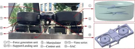
Fig.1 Configuration of the aerial robot from BIT.
Concerning the anti-disturbance control technology,some researchproposes improved optimal robust control structures based on optimization methods.Other research meanwhile,introduces a series of improved SMCs (sliding mode controller) to ensure stable performance against unmatched disturbances.In addition,based on the MRAC(model reference adaptive control) theory,a control structure for selecting different reference systems for different disturbances is proposed;this will improve the performance of the closed-loop system.However,all of the above mentioned control methods are only able to deal with disturbances below the CDG(critical disturbance gain).In this research,,and a corresponding control strategy&algorithm will also be introduced in the following sections.
The remaining sections of this paper are arranged as follows:In Section 2,the design process of an adaptive nominal controller is introduced,and the disturbance boundary of the controller is also analyzed based on the disturbance model.In Section 3,the nonlinear dynamic model of the proposed SAC is established,and the corresponding controller is studied as well.In Sections 4 and 5,the simulations and tests of the proposed control structure are introduced to verify the control targets.Finally,section 6 examines some of the conclusions based on the results drawn from the research.
2.Nominal controller design and disturbance analysis
2.1.System modelling under modeling error and external disturbance
Here are some assumptions:
1.Since this research is only concerned with the performance of attitude states,the external disturbances can be reasonably simplified as unknown torques that are found along each attitude direction.
2.The external disturbances are bounded.
Based on the above assumptions,the dynamic equations from the external disturbances to the attitude states of the aerial robot can be derived as follows:


In our previous research,the state space model of the proposed aerial robot was obtained through frequency domain identification.In order to streamline the following derivation,the state space model is denoted as:


where Eand u()respectively represent the disturbance input matrix and vector:

Taking the modeling error into consideration,the state space model of the robot is displayed as:

where σ() is a diagonal square matrix displaying the unknown modeling error of each input channel,thus completing the disturbance model.In the following parts of this section,a nominal controller will be applied to ensure basic performance and provide modeling error compensation.
2.2.Nominal controller design
Fig.2 shows the configuration of the nominal controller for the proposed aerial robot in Eq.(6).The nominal controller consists of three loops:(A) the state feedback loop is applied to achieve input-output decoupling and ensure basic performance against regular external disturbance;(B) the adaptive loop is designed to estimate the modeling error;and (C) the tracking loop is responsible for attitude tracking.The state feedback controller is designed as a static matrix via H-infinity synthesis and the tracking controller is a series of PD regulators;the detailed theory and design process can be checked in our previous research.In this paper,we will focus on the introduction of the adaptive controller.
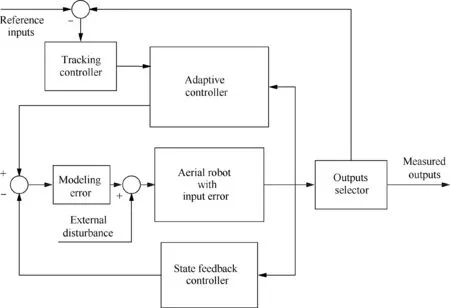
Fig.2 Configuration of the nominal controller.
According to the configuration in Fig.2,the adaptive controller is applied to the closed-loop system (employed by the state feedback controller).Therefore,the modeling error and disturbance should be transformed into the closed-loop system:

where u()is the closed-loop input vector and the closed-loop matrix A,modeling error σ(),and state uncertainty ω()are able to be derived from the open-loop matrix and state feedback controller:

where Krepresents the static feedback matrix.The configuration of the transformation from‘‘open-loop”to‘‘closed-loop”is displayed in Fig.3.

Fig.3 Transformation from open-loop system to the closed-loop system.
Since the input and output channels of the proposed aerial robot have been decoupled by the state feedback controller,the closed-loop model in Eq.(7) can be reasonably rewritten as:where the subscript i ∈[1,3 ] denotes the ichannel.

For the system described in Eq.(9),one of the control targets of this research proposes an adaptive controller to estimate and compensate the closed-loop input and state errors.Fig.4 displays the configuration of the adaptive controller.
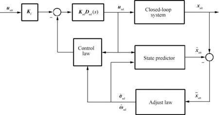
Fig.4 Configuration of the adaptive controller.
According to the configuration of the adaptive controller,it contains three main parts:(A) the state predictor is designed for state prediction;(B) the adjustment law is applied based on the state predictor in order to provide an estimate of the modeling error;and (C) the control law is designed according to the modeling error estimation and is reconfigurable in order to compensate for any uncertainties.In the following parts,we will breakdown the design process of the adaptive controller.
In the first step,we consider the following state predictor for the system in Eq.(9):
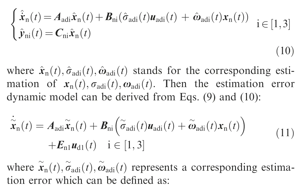

According to the expression in Eq.(11),once an effective adjustment law of the closed-loop input and state uncertainties is designed,with the aim to guarantee the stability of estimation error system,then the state prediction will be asymptotically convergent.According to Lyapunov’s stability theory,we consider the following candidate function:
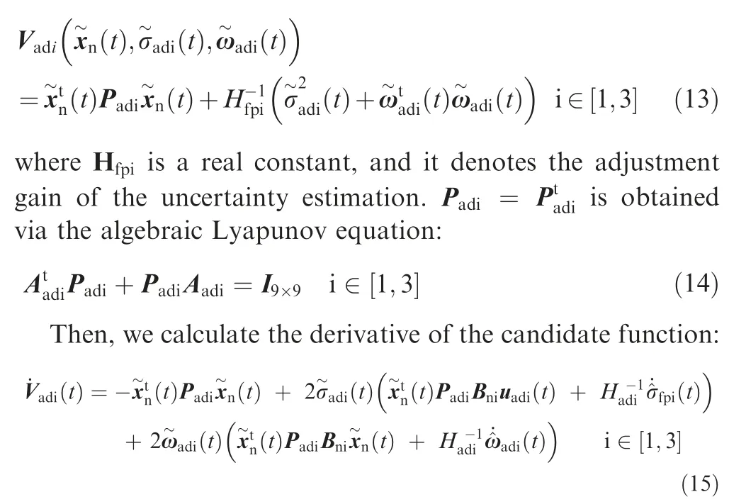
According to the Lyapunov stability criterion,the proposed state prediction will converge if the uncertainty estimations satisfy the following adjustment law:

From the derivation in Eq.(16)we find that the adjustment law of the input and state error is concerned with the state predictor error,which means that once there exists a state predictor failure,the uncertainty estimation may become divergent and lead to oscillations in the system.In order to avoid this problem,a projection operator is applied,and the adjustment law can be replaced by:

The projection operator is actually a piecewise function.If the state predictor works well,the output of the projection operator is the same as Eq.(16),while when the state prediction tends to be divergent,the uncertainty estimations are limited between the bounds of the projection operator.A detailed expression of the projection operator can be referred to in Ref..
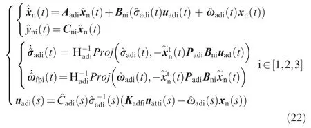
Finally,based on the uncertainty estimations,the control law is able to be designed as:

where Kis a feed-forward regulator which is applied to ensure tracking performance,and() is a low-pass filter concerned with modeling error estimation.These control elements are derived as follows:


where the decision system G() and constant boundare defined as:

Thus,the adaptive controller against modeling error has been completed.Summing up then,under the norm condition in Eq.(20),the proposed adaptive controller is:
2.3.Disturbance boundary analysis
The external disturbance on the closed-loop system will lead to:(A) the decrease of the system’s controllability;and (A)input saturation.Generally,in the case of input saturation,the system is still controllable.Therefore,in order to obtain a stricter disturbance tolerance boundary,the input saturation gains for each channel must be calculated:
Fig.5 displays the plots of the closed-loop responses varying with the gain of the external disturbance in hover.Notice that in this research,the input elements are normalized within[-1,1].According to the calculation results:
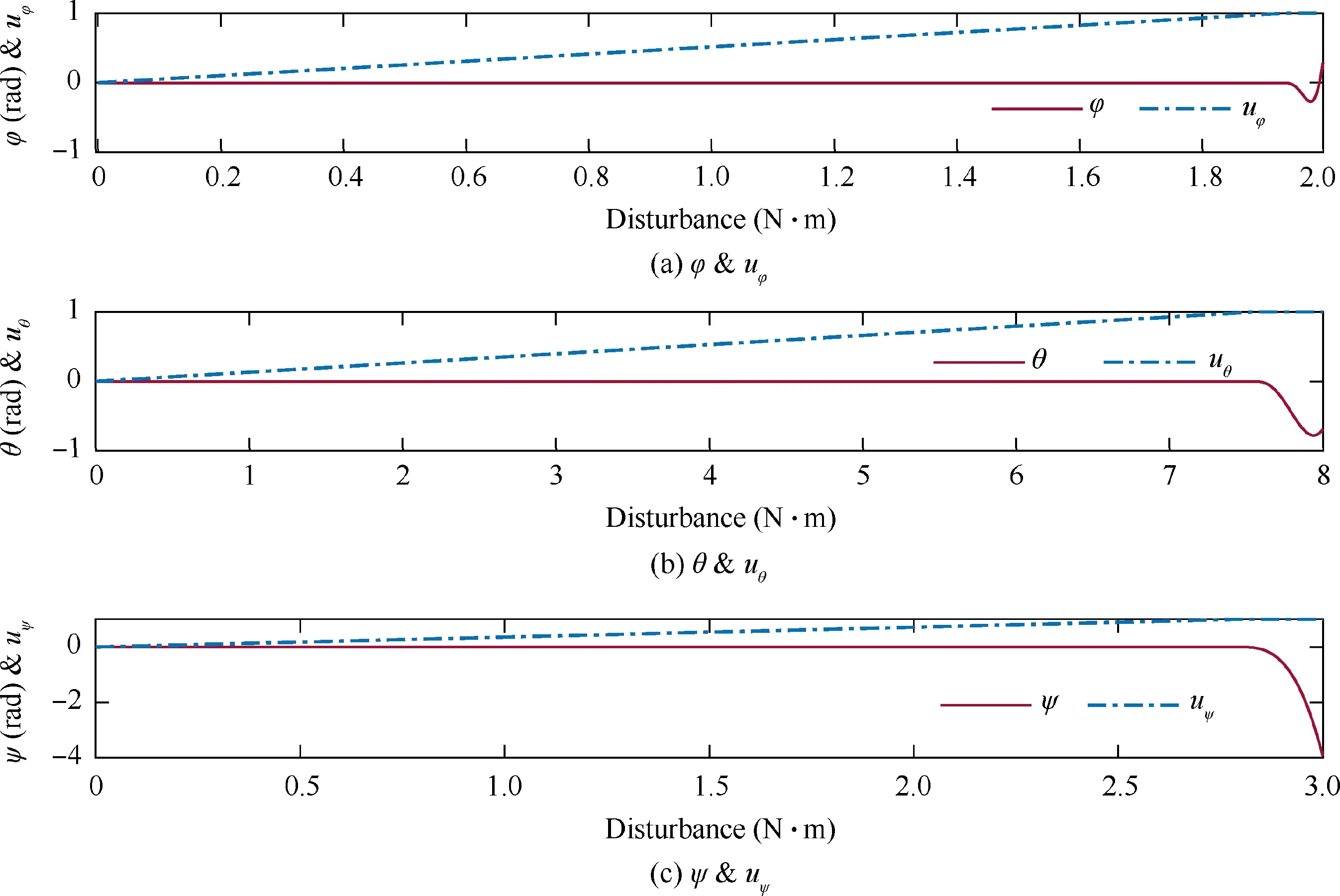
Fig.5 Plot of input saturation gain.
(1) When the external disturbances reach 1.84 N·m,7.4 N·m,and 2.7 N·m respectively,the input of the corresponding channel becomes saturated.Here,the three critical values are defined as the CDG.The proposed control structure is robust against any external disturbance lower than the CDG,while when the disturbance is larger than the CDG,the system loses its stability which means that the controller cannot deal with disturbance beyond the CDG.
(2) The CDG of the rolling channel is much lower than the other two channels which indicates that the rolling channel’s anti-disturbance ability performs worst of them all.This is caused by the aerodynamic layout of the aerial robot.The control force/torque of the rolling channel is limited by the size and position of the vane series.Moreover,the bandwidth of the rolling channel is large which also leads to a high sensitivity to disturbance.
Through the analysis of the CDG for each channel,the other main control target of this research becomes clear:improving the anti-disturbance capacity of the rolling channel.However,according to the above analysis,when the external disturbance reaches its CDG,the input is already saturated.In the following section,a novel attitude stabilization structure is proposed to solve this problem,and its corresponding control strategy is also studied accordingly.
3.Attitude stabilization and the corresponding control structure design
The CDG analysis in Section 2 indicates that in order to improve the anti-disturbance capacity of the rolling channel,extra structure has to be applied to generate more control force/torque.Motivated by the configuration of the CMG(which is applied for aerospace craft),a novel gyroscopic moment generator is designed to be used as the SAC of the rolling channel.In the following parts of this section,we are going to establish the dynamic model of the SAC,and display the corresponding control strategy and algorithm.
3.1.Dynamic modelling of the attitude stabilization structure
Fig.6 displays the configuration of the proposed SAC.According to the configuration,the SAC consists of three parts:(A) the shaft;(B) the high-speed flywheel;and (C) the flywheel cage.Fig.6 also shows the coordinate system of the SAC.The coordinate system mainly contains three parts:(A)the inertial coordinate (which is related to the ground);(B)the body coordinate (which is related to the shaft);and (C)the flywheel coordinate (which is related to the flywheel cage).In order to streamline the following derivation,the parameters and corresponding symbols of the SAC are displayed in Table 1.
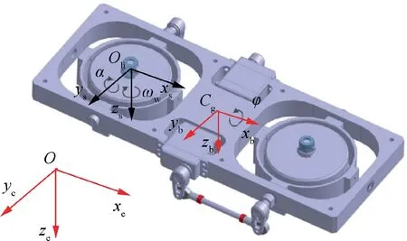
Fig.6 Configuration of the stability augmentation structure.
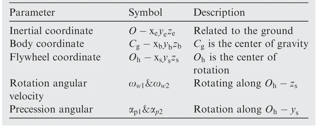
Table 1 Llist of parameters of SAC.
Taking one of the two flywheels as an example,when a high-speed rotating flywheel (along-) proceeds along with-at the same time,there will be a gyroscopic moment generated along C-x.The above description explains the generation mechanism of the extra rolling channel control moment.Before the SAC modelling,it should be explained that:
(1) The rotation angular velocities of the two flywheels are always both equal and opposite along their rotation axis in order to ensure a counter-torque balance.Which means that ω=-ω.

Then,several assumptions should be noted before modelling:
(1) It is assumed that the SAC is only applied to the rolling channel of the aerial robot.This indicates that in this research we should only be concerned with the dynamic characteristics of the rolling channel with the SAC.
(2) It is assumed that the aerial robot always works in hover conditions.This indicates that the rolling channel model should ideally only contain one degree of freedom along the rolling axis.
(3) It is assumed that the COG (center of gravity) of the SAC and aerial robot are completely coincident.This means that the body coordinate of the aerial robot is the same as C-xyz.
(4) It is assumed that the mass,rotation velocities,and precession velocities of the two flywheels in the SAC are exactly the same.This means that the dynamic characteristics of the two flywheels are the same and that the gyroscopic moments generated by the two flywheels can be reasonably directly added.
Then,we are going to establish the dynamic model of our aerial robot with the proposed SAC.Since the SAC consists of three rigid bodies,the model will be established based on the Lagrange multiple rigid body dynamic theory.According to the above assumptions,it can be deduced that each rigid body’s motion is rotational.Therefore,the velocity of each rigid body within the related coordinates can be derived by the following equations:

where ω,ω,and ωrepresent the respective angle velocities of the aerial robot with the SAC,flywheel cage,and flywheel in corresponding coordinates,[i,j,k] is a unit basis vector of coordinates *.It should also be noted that only one series of the flywheel and its corresponding cage are taken into consideration in Eq.(23).Then,the kinetic energy of each rigid body is able to be calculated as:


According to Eq.(26),the Lagrange function can be obtained:

whererepresents the total kinetic energy including the aerial robot and the SAC,represents the total generalized moments including the control torque generated by the vane series and unknown disturbance.The moment generated by the vane series Tcan be calculated as:

whereis the distance from the lift center of the vane to,and,these are aerodynamic forces generated by the two vane series.The detailed calculation ofandcan be checked in Ref..Finally,the nonlinear model of the rolling channel with the SAC can be derived by solving the Lagrange function in Eq.(27):


3.2.Strategy of disturbance compensation control
According to the dynamic model in Eq.(29),the rolling channel with the SAC is a multiple-input and single-output system.The output of the system is actually the generalized coordinate:rolling angle φ.The inputs consist of two parts:(A) the control moment generated by the vane series;and(B)the control moment generated by the SAC.Therefore,this research proposes an input gain scheduling strategy.
For the strategy,the vane series is defined as the main actuator while the SAC is applied as the auxiliary actuator.The scheduling strategy can be described as:

where u()represents the control signal calculated by the controller of the SAC,and Δis defined as the saturation coefficient which is calculated as:

According to the definition in Eq.(30),the mechanism of the scheduling strategy is clear:
(1)When the vane series is not saturated(which means that the external disturbance is lower than the CDG),then the SAC does not work and thus the control moment,generated by the vane,performs as the only control input to provide a highfrequency attitude regulation.
(2)When the vane series is saturated(which means that the external disturbance is beyond the CDG),then the SAC begin to work and the gyroscopic moment,which is generated by the SAC,is performed as another control input in order to compensate for the strong transient disturbance.
In order to express this more clearly,the configuration of the proposed scheduling strategy is displayed in Fig.7.In the configuration,the input gain scheduling strategy is modelled as a condition-dependent switch;the system input is selected depending on the saturation condition of the vane series.
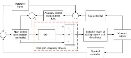
Fig.7 Configuration of the input gain scheduling strategy.
3.3.Controller design of the stability augmentation structure
In Section 2,referring to the scheduling strategy in Eq.(30),the adaptive control law u() has been designed.In the following parts of this section,the control law of the SAC u() will be introduced.
According to the dynamic model in Eq.(29),when taking the SAC into consideration,the rolling channel of the aerial robot in this research will become a system with strong nonlinear characteristics.Therefore,the controller u() will be developed based on the SMC theory.The SMC controller is an effective variable structure controller,and because of its discontinuity,it is also essentially a nonlinear control structure.The classical SMC theory appeared in the 1950s and after nearly 70 years of development,it has become an independent and common research branch of automatic control.The SMC controller has been widely used in the engineering practice of linear and nonlinear systems,continuous and discrete systems,as well as in certain and uncertain systems.The most important feature of this control structure is that the state of the system slides along the sliding surface through the switching of control variables.This then ensures that the state of the system remains unchanged even under parameter perturbation or external disturbance.In this research,a SMC controller will be designed according to the dynamic characteristic of the SAC.
First,the dynamic model of the rolling channel with the SMC is rewritten in the following standard form:
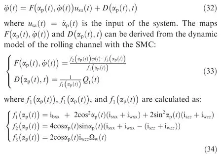
In order to find the effective gains of the SMC,we consider the following surface function:

whereis a constant gain,()=φ()-φ() displays the tracking error.According to the SMC theory,the sliding surface function is Hurwitz,which means that the selection ofhas to satisfy the following condition:

Then,the derivative of the sliding surface function can be calculated:

Following the Lyapunov theory,if the error dynamic system described in Eq.(35) is asymptotic stable,then the tracking error will be convergent.According to this design criteria,the following Lyapunov candidate function is considered:

Calculating the derivative of the candidate function,and substituting Eq.(37) for it,we can get:

According to Lyapunov’s stability theorem,the control law of the SAC can be designed as:

where ηis a designed constant gain,and(())is a sign function depending on the value of(),by substituting Eq.(40) for Eq.(39),we can get:

Then,if the constant gain ηis designed to satisfy the following condition:

The derivative of the candidate function will become negative,which means(according to Lyapunov’s stability theorem)that the tracking error will converge to zero:


where the saturation function is defined as:

where Δis a real constant representing the design margin.According to the definition in Eq.(45),the mechanism of the control law in Eq.(44) is clear:when the sliding function is beyond the design margin,the control law is actually the same as equation Eq.(40).When the sliding function is within design margin however,the() of the SAC is transformed into a feedback controller which will reduce the input signal chattering during fast sliding-mode switching.
4.Simulation verification
4.1.Controller parameters design
Referring to the condition in Eq.(20),the selection of the adaptive controller parameters can be transformed into the following optimization:

(())∈(()),i ∈[1,2,3]
where(*)displays the bandwidth of the transfer function*.Notice that the optimization in Eq.(46) is related to two parametersand().In this research however,the filter() is reasonably simplified as an integral filter:

Thus,Eq.(46) can be reduced to a single parameter optimization problem.With the help of the toolbox embed in Matlab®,the constant control parameteris obtained as:

With the following norm boundaries:

And then,as was discussed in Section 3,the parameters of the sliding term for the SMC controller of the SAC have to satisfy the following conditions:

After some iterations and adjustments,the parameters in this research are selected as follows:

Finally,the adjustment gains of each input and output channel are designed as:

4.2.Simulation scenarios and results
It should be stated again that this research’s control targets consist of three aspects:
(1) Design an adaptive controller to compensate for the modeling error.
(2) Design an attitude stabilization structure and its corresponding controller in order to improve the antidisturbance capability of the rolling channel.The value of the disturbance used in this research should be greater than the CDG of the rolling channel.
(3) The torques caused by the movements of the manipulator are considered as parts of the external disturbances and the kinematics and dynamics parameters of the manipulator can be found in our recently research.
In order to verify the above two control targets,the simulations were divided into two parts.In the first part,we simulated the performances under modeling error.For a more comprehensive consideration,both constant and timevarying modeling errors were simulated.The simulation parameters are set as follows:

In scenarioand,we tested the steady and transient performance of the aerial robot under a 40% constant modeling error;in scenarioand,we tested the steady and transient performance of the aerial robot under a 40% timevarying modeling error.The simulation results are displayed in the following figures:
Fig.8 displays the closed-loop responses and system inputs of scenarioand.In Fig.8(a),the first 30 represent steady performance simulation and the last 30 represent transient performance simulation.In order to show the advantages of the proposed adaptive controller,the responses have been compared to the baseline controller in our previous work.The legend ‘‘AC ON” in the figure shows that the adaptive controller is working,while the legend ‘‘AC OFF”means that the adaptive controller is not working and that the aerial robot is only run by the baseline controller.Fig.8(b) also plots the system inputs calculated by the corresponding controllers.
According to the simulation results,the proposed adaptive controller shows great improvements.The performance of the baseline controller indicates that it is not able to be robust in the face of a 40% modeling error.The responses of the baseline controller show oscillation,delay,and steady tracking error.The rolling channel performs worst of all as its corresponding input is seriously saturated.On the other hand,the performance of the proposed adaptive controller is great.The response of the steady step reference input shows excellent tracking performance with nearly no oscillation or overshoot.The transient performance of the adaptive controller is also satisfactory.Tracking delays do exist in the transient response however,but the tracking error is reasonably slight.
Fig.9 displays the closed-loop responses and system inputs of scenarioand.In Fig.9(a),the first 30 represent a steady performance simulation and the last 30 represent a transient performance simulation.The legends in the figure are the same as in Fig.8.
When comparing the simulation results in Fig.9 to the performance inand,there is an indication that the timevarying modeling error is more of a challenge than the constant modeling error.The baseline controller becomes unstable under a 40% time-varying modeling error and the response of each channel is completely untraceable,while on the other hand,this kind of modeling error does not seem to cause much trouble for the adaptive controller.Here,both the steady and transient performances show great improvement when compared with those from the baseline controller.The tracking response of the adaptive controller show slight oscillations and the tracking delay also increases slightly when compared with Fig.8.However,when looking at the comprehensive performance,it is still satisfactory.This indicates that the proposed adaptive controller is robust to both constant and time-varying modeling errors.
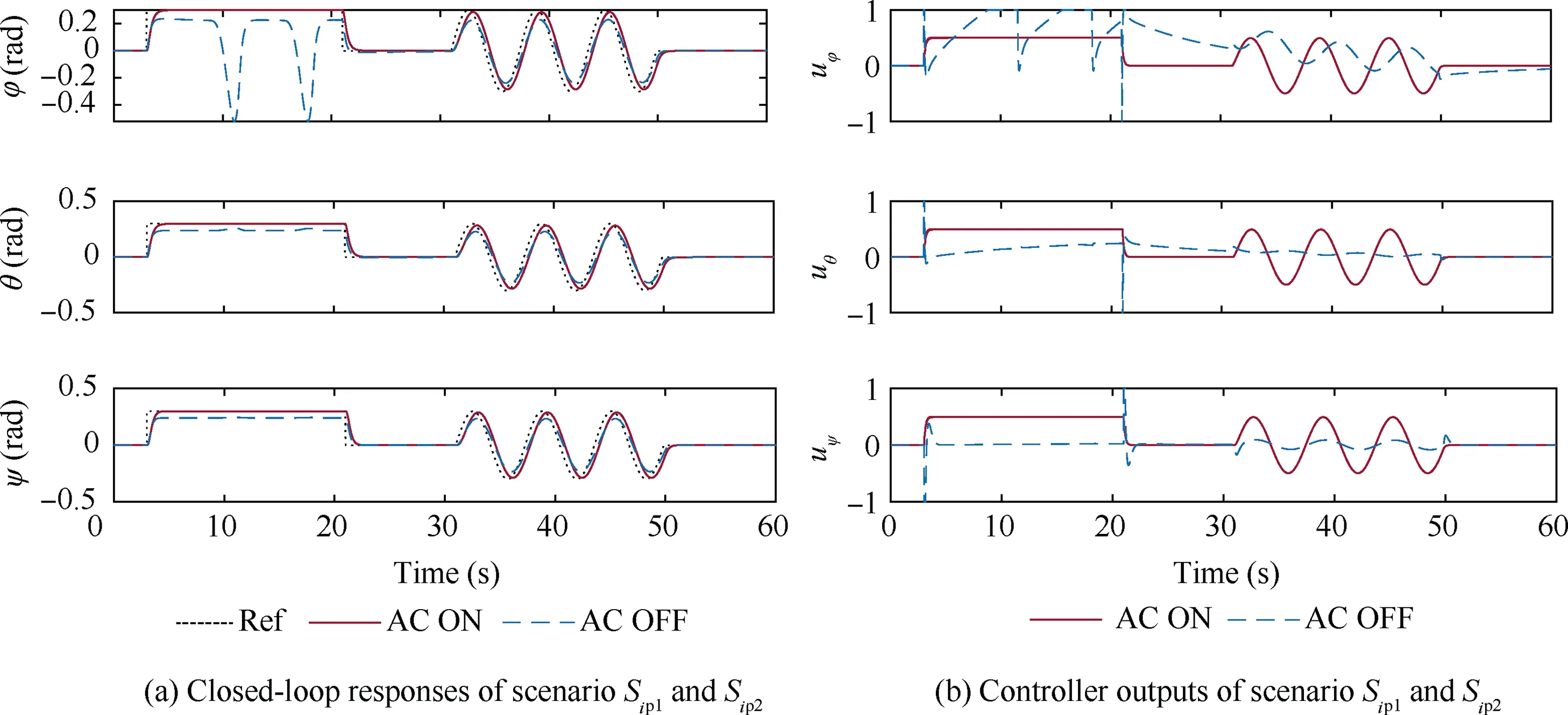
Fig.8 Closed-loop responses and system inputs against steady modeling error.
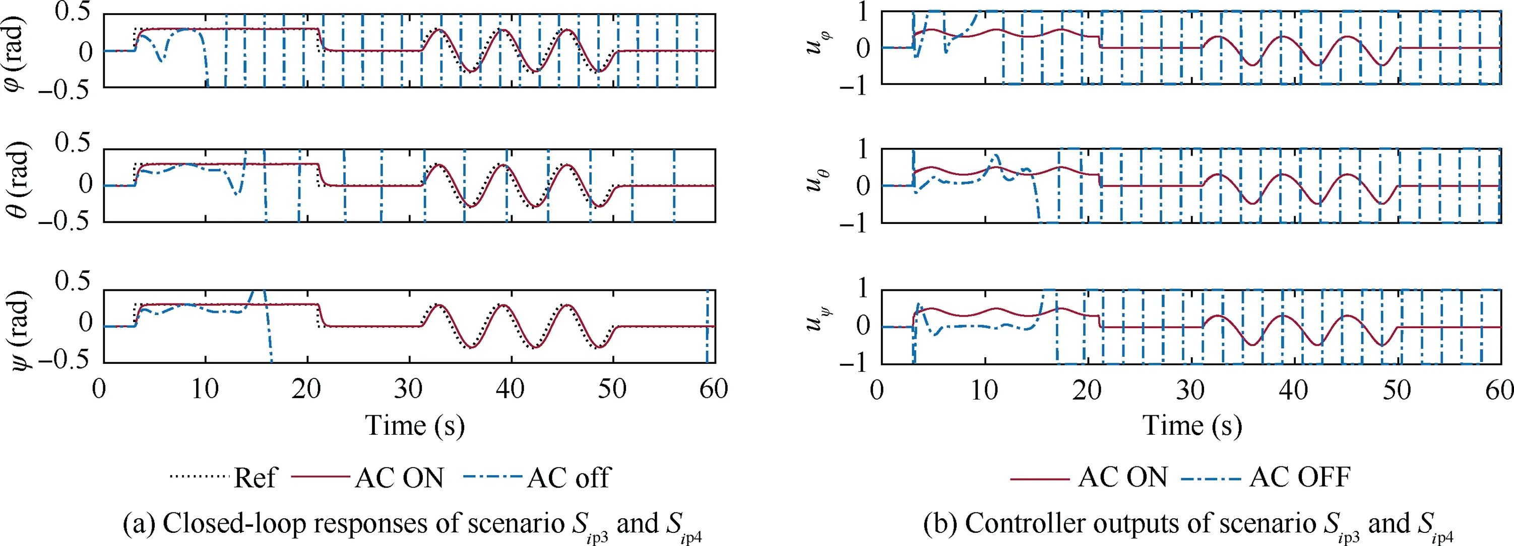
Fig.9 Closed-loop responses and system inputs against time-varying modeling error.
In order to quantify the compensation capability of the proposed adaptive controller,the modeling error estimations are calculated and plotted in Fig.10.The upper plot in Fig.10 displays the estimation of the constant modeling error,while the lower plot shows the estimation of the time-varying modeling error.The first 30 represent the estimation performance from a steady reference input;while the last 30 show the estimation performance from a transient reference input.
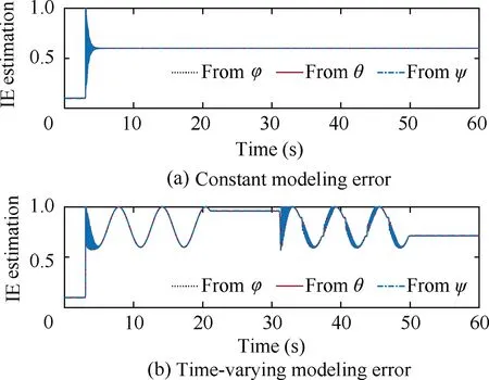
Fig.10 Estimations of constant and time-varying modeling error.
The estimation results in Fig.10 indicate that the timevarying modeling error is challenging,and that the transient reference input represents an even greater challenge still.Further results show that the estimation performance of the constant modeling error is good,and that when dealing with the time-varying modeling error,the convergence time is longer.However,the estimations can be settled down within 3 s with no error.As results displayed in Fig.9,when the reference input is time-varying,the estimation also shows a timevarying error which leads to a delay in attitude tracking.
At the end of this section,we will display the performance of the proposed SAC with its SMC controller against the external disturbance.The simulation parameters are set as follows:

where() is an impulse function which is used to simulate transient disturbance.The absolute amplitude of the impulse function is|()|=4 >1.84 which means that the external disturbance selected in the simulations is larger than the CDG of the rolling channel.
Fig.11 displays the simulation results of the rolling channel with the SAC.The upper plot is the simulation disturbance;the center plot is the rolling angle response;and the lower plot is the system input calculated by the proposed SMC controller.In Fig.11,the first 30 represent the steady performance simulation and the last 30 show the transient performance simulation.
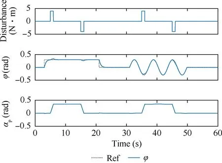
Fig.11 The response of rolling channel with SAC.

5.Experimental verification
5.1.Flight test under modeling error
The flight test in this research is dependent on the OptiTrack®real-time tracking system.This tracking system is the most popular choice for researchers in related studies as it is able to provide low latency and precision 6DoF tracking for both ground and aerial robotics.The free developer tools from OptiTrack® provide access to camera images,centroids,reconstructed 3D points,as well as providing access to a rigid body position and orientation.Their Natnet SDK provides free and open documented access to the tracking system’s real-time stream which can then easily be integrated into the researcher’s own control system.The SDK also provides compatible interfaces with Matlab®or ROS®which makes it both easier and more user-friendly for researchers.
Fig.12 displays the configuration of the tracking system.The system consists of two parts:(A) the infrared camera series;and (B) the ground station.The ground station is a personal computer embedded with a Micron Series calibration tool,and it is also responsible for monitoring the real-time location of the aerial robot.The infrared camera series in this research contain 24 cameras which are able to provide an effective location space of 6×6×2 m.
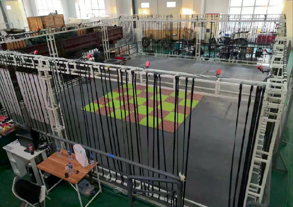
Fig.12 Configuration of the OptiTrack® real-time tracking system.
Fig.13 shows the calibrated experimental space and the agent of the aerial robot.It should be noted that the proposed aerial robot has been marked with six reflections shown as a hexahedron agent,and there is another reflection placed near the COG of the aerial robot which is used for location tracking.What’s more,the control algorithm to be verified is coded through rapid prototyping tools developed by Quanser®.Table 2 shows some information about the hardware that was used in this test.
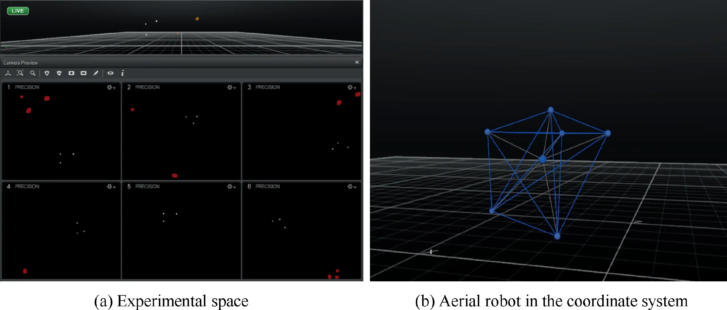
Fig.13 Experimental space and the marked aerial robot models supported by Quarc®.
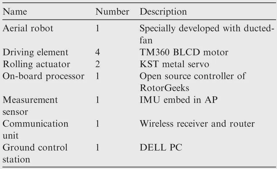
Table 2 List of hardware.
It should be explained that during the test,the modeling error was simulated by the saturation of the input gain.Taking the safety of the test into consideration,the input signal fromeach channel was limited to 80% of its original,thus simulating a 20%modeling error.The controller applied in our previous researchwas also tested for use as a non-adaptive comparison.
The flight test results are plotted in Figs.14 and 15 with Fig.14 displaying the attitude tracking performance under modeling error,and Fig.15 showing the position tracking performance.It should be noted that the height controllers of the two tested control structures are the same,so the flight data along the z-axis is not plotted here.According to the test results,when the proposed adaptive controller works,the tracking performance is obviously improved.When compared with the developments in the attitude tracking performance in Fig.14,a greater improvement can be seen in the developments of the position tracking performance in Fig.15.These flight results indicate that the attitude tracking error may be integrated.This then leads to large position tracking errors and thus improvements in attitude control performance must be contributed to improvements in the corresponding tracking performance Table 3.
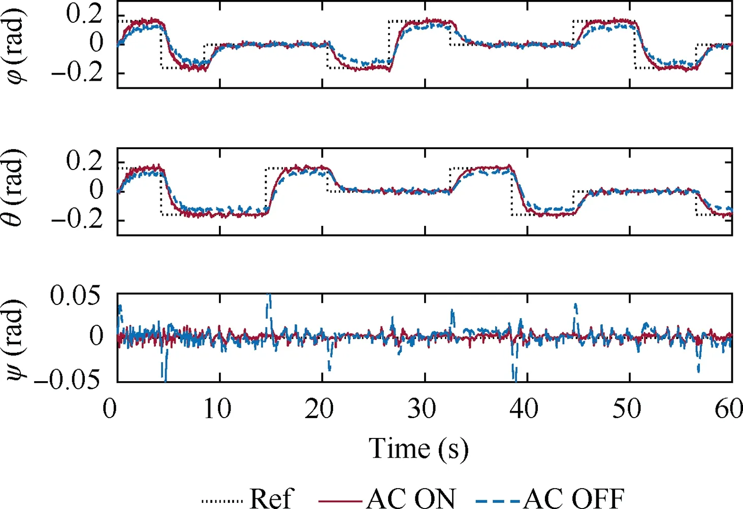
Fig.14 Attitude tracking performance.
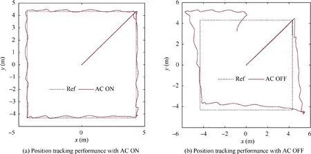
Fig.15 Position tracking performance.
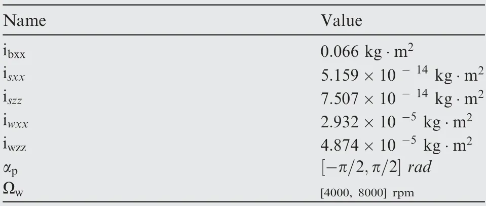
Table 3 List of parameters.
5.2.Prototype verification of SAC under transient external disturbance
Since the application of the SAC on an UAV has no reference to follow,in this research a prototype of the SAC was designed and applied to verify the mechanism proposed in Section 3.
Fig.16 displays the configuration of the verification prototype of the SAC,the parameters of the prototype are listed in the following table.
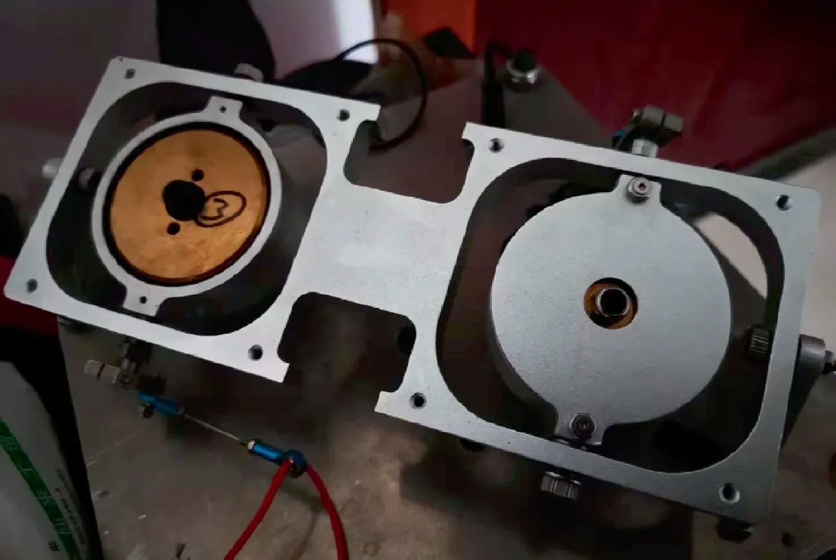
Fig.16 Verification prototype of SAC.
Similar to the flight test in the last part of this section,the core control algorithms proposed in Section 3 are coded through the rapid prototyping tool,the results of the test are plotted in Fig.17.
Fig.17 shows the anti-disturbance responses of the verification prototype.Since the aim of this test is to verify the working mechanism of the SAC,we have only concerned ourselves with the tendencies of the proposed controller.Therefore,the level of disturbance is not quantized in this test.During the test,the reference input of rolling channel remained at zero.At 10,a standard mass block (100 g) was released from a height of 2 m;something which was done in order to generate the transient disturbance.According to the test results,there was an oscillation in the rolling angle response plot within 0.1 rad,which is considered reasonably small.From this we saw that from the system input’s precession angle plots,it is clear that when encountering external disturbance,the rolling angle changes,then the SAC is driven by the controller to generate control moment which is then able to ensure the stability and tracking performance of the rolling channel.
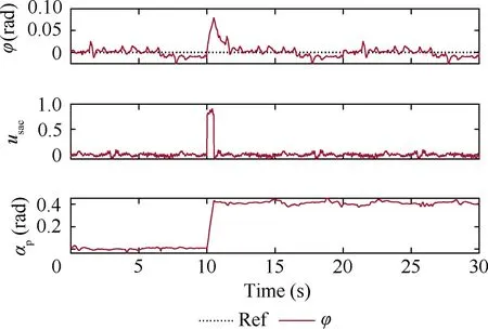
Fig.17 Anti-disturbance test.
6.Conclusions
This research provides a special developed SAC for a ductedfan aerial robot performing under modeling error and large transient external disturbance.At the beginning of this research paper,an adaptive nominal controller was proposed to compensate for any modeling error.During the process of working on the nominal controller design,the disturbance dynamic model was established to quantify the antidisturbance capacity of the aerial robot.According to the anti-disturbance analysis,the CDG of the rolling channel is much lower than the others which thus lead to the necessity of the SAC.Then,the special SAC was devised based on the CMG theory and a nonlinear dynamic model of the rolling channel with the SAC was also established in order to develop its corresponding controller(via the SMC theory)and scheduling strategy.Finally,the simulations and tests verified that:(A)the proposed adaptive controller is robust to both constant and time-varying modeling error;and (B) the SAC is able to maintain stability along the rolling direction in the case of transient external disturbance.Since the tests on the SAC presented in this paper only verify its working mechanism,in further research we plan to apply the SAC to aerial robot flight tests.What’s more,accurate measurement methods and disturbance application will also be studied at a later date.
The authors declare that they have no known competing financial interests or personal relationships that could have appeared to influence the work reported in this paper.
This study was co-supported by the National Key Research and Development Program of China (No.2020YFC1512500)and the National Natural Science Foundation of Chongqing,China (No.cstc2020jcyj-msxm3857).
 Chinese Journal of Aeronautics2022年2期
- Chinese Journal of Aeronautics的其它文章
- Pressure-induced instability and its coupled aeroelasticity of inflated pillow
- Adjoint boundary sensitivity method to assess the effect of nonuniform boundary conditions
- Transit time difference and equal or non-equal transit time theory for airfoils with lift
- A boundary surrogate model for micro/nano grooved surface structure applied in turbulence flow control over airfoil
- Nonlinear uncertainty quantification of the impact of geometric variability on compressor performance using an adjoint method
- High precision and efficiency robotic milling of complex parts:Challenges,approaches and trends
