Flight control of a large-scale flapping-wing flying robotic bird:System development and flight experiment
Wenfu XU ,Erzhen PAN ,Junto LIU ,Yihong LI ,Hn YUAN,*
a School of Mechanical Engineering and Automation,Harbin Institute of Technology,Shenzhen 518055,China
b State Key Laboratory of Robotics and System,Harbin Institute of Technology,Harbin 150001,China
KEYWORDS Autonomous flight control;Flapping-wing;FreeRTOS;HIT-Phoenix;Robotic bird
Abstract Large-scale flapping-wing flying robotic birds have huge application potential in outdoor tasks,such as military reconnaissance,environment exploring,disaster rescue and so on.In this paper,a multiple modes flight control method and system are proposed for a large-scale robotic bird which has 2.3 m wingspan and 650 g mass.Different from small flapping wing aerial vehicle,the mass of its wings cannot be neglected and the flapping frequency are much lower.Therefore,the influence of transient aerodynamics instead of only mean value are considered in attitude estimation and controller design.Moreover,flight attitude and trajectory are highly coupled,and the robot has only three actuators----one for wings flapping and two for tail adjustment,it is very difficult to simultaneously control the attitude and position.Hence,a fuzzy control strategy is addressed to determine the command of each actuator by considering the priority of attitude stabilization,trajectory tracking and the flight safety.Then,the on-board controller is designed based on Free-RTOS.It not only satisfies the strict restrictions on mass,size,power and space but also meets the autonomous,semi-autonomous and manual flight control requirements.Finally,the developed control system was integrated to the robotic prototype,HIT-phoenix.Flight experiments under different environment conditions such as sunny and windy weather were completed to verify the control method and system.
1.Introduction
In recent years,considerable attention has been paid in flapping-wing flying robotic birds,which is a novel unmanned aerial vehicle different from fixed-wing aerial vehicle and rotors.Compared with other types of drones,Flapping-Wing Aerial Vehicle (FWAV) has advantages of high aerodynamic efficiency,low flight noise,high maneuverability and robustness to disturbance.In addition,it has great application prospects in some special fields such as national defense due to its bionic appearance.Based on these advantages,many institutions have begun to study FWAVsor FWAVs in combination with other types of aircraft.For example,the tailless micro FWAV Nano Hummingbirdwas unveiled,which has a mass of 19 g,wingspan of 16.5 cm and can hover for several minutes.DelFly projectcreated many versions of micro FWAVs such as DelFly I,DelFly II,DelFly Micro and DelFly explorer,all of them can perform free-flight with onboard energy source,while some of other micro FMAVs cannot fly freely because the load capacity is too small to carry onboard energy source.Northwestern Polytechnical University developed a 50 cm wingspan FWAV ‘‘Dove”.For the above FWAVs,their size and weight are generally small.Although they have certain flight performance,and a lot of performance optimization work based on materialmechanical structureand aerodynamicshave been down,the flight performance(such as flight duration,height and distance,wind resistance capability and so on)and payload carrying ability are still very confined.
To perform long-time and long-distance outdoor flight missions for carrying larger payload,large-scale flapping-wing flying robots are required.The typical large-scale flapping-wing flying robots include SmartBird developed by Festo,RoboRaven developed by University of Maryland,and the HIT-Hawk developed by Harbin Institute of Technology(HIT).These prototypes have relatively good flight performance and larger payload carrying ability.
Autonomous flight control is very important for a flying robot.There are some research achievements in the field of flight control of FWAVs.Theoretical analysis and experimental researchare combined to propose the source of flying capabilities of FWAVs and the influence of various parameters on flight control.Various analyses of flight dynamics,stability and controlof FWAV were reviewed.A six Degree Of Freedoms(DOFs)nonlinear and time-varying dynamic model of a typical hummingbird is constructed for simulation studies.1They use the average theory and quasi-steady assumptions to design an adaptive controller.A high-fidelity nonlinear and time-periodic dynamic modeof micro FWAV was developed and the simulation of trajectory tracking was done to verify the correctness of their model.In addition to theoretical studies,many experimental studieswere carried out to develop aerodynamics of FWAV,a miniature six-component force transducer and Particle Image Velocimetry (PIV) measurement were used to study the aerodynamic characteristics.In addition,Uncertainty and Disturbance Estimator (UDE)based control with output feedback for FWAV systemswere proposed,which can achieve the acquisition of the approximate plant model with only a partial knowledge of system parameters.The dynamics model of FWAV based on quasisteady-state aerodynamic theory and a corresponding saturated feedback controllerwere proposed.They were verified through numerical simulations and prototype experiments.The trajectory tracking control algorithmdeveloped by utilizing the boundary control was used to regulate the displacements in bending and twisting of wing to track two spatiotemporally varying trajectories.In addition,the performance of the prototype is critical to the actual flight control effect.To improves the mobility and the flexibility of FWAV,a boundary control approach is used to control a two-link rigid-flexible wing.This method can restrain the vibrations in bending and twist deflections of the flexible link of the wing and achieving the desired angular position of the wing,which greatly increases the control capability of aircraft.
According to the brief overview of related work above,we find that most researches are aimed at the flight control of micro FWAVs,whose aerodynamics can be largely simplified and flapping frequency is relatively high,the quasi-steady assumptions and periodic average theory can be easily used in it.In addition,they are generally very light and the wings are generally less than 6 percent of the body mass.Hence,smaller lift force can make them fly and the mass and associated inertia effects of the wings can be neglected.That is to say,the flight condition is relative good.However,for a large-scale flapping-wing robotic bird,it has long wings and heavy body.The total mass is much larger than a small FWAV.The mass and inertia of the wings are also too large to be neglected.In addition,its flapping frequency is generally low due to the constraints on driving mechanism and structure strength.Moreover,according to aerodynamics,the flight attitude and trajectory are highly coupled,but most FWAVs are only driven by a few actuators due to strict limitation on mass,power and space.For example,only three motors are used for HIT-Phoenix ----one for wings flapping and two for rail adjusting.That is to say,only three state variables can be actually controlled but the robot has six DOFs.Therefore,the autonomous flight control of a large FWAV is very challenging.Most publicly reported FWAV with wingspans greater than 1 m are manually controlled.
In recent years,we have been devoting to develop large FWAVs.Two mature prototypes with stable flight performance are HIT-Hawk and HIT-Phoenix.The former has 1.6 m wingspan and 450 g mass;the latter has 2.3 m wingspan and 650 g mass.Based on the latter work,we focus on studying the autonomous flight control method and system.In this paper,we will introduce the work about the flight control of HIT-Phoenix.The main contributions are as follows:(A) A multiple modes flight control method is proposed and realized in on-onboard controllers for a large-scale robotic bird.The influence of transient aerodynamics dependent on the mass of its wings and the low flapping frequency performance are considered in attitude estimation and controller design.(B)To deal with the highly coupling between the attitude and position,and the limited actuating ability under only three motors,a fuzzy strategy combined with priority criterion is proposed to realize both attitude stabilization and trajectory tracking.(C)A highly integrated onboard controller is developed;it satisfies the strict restrictions on mass,size,power and shape.The control algorithm is realized in the real-time embedded operating system FreeRTOS to obtain better task scheduling performance and 500 Hz control frequency,making the flight control be robust to the FWAV’s low frequency flapping motion.(D)The global control system,composed by the onboard controller,remote controller and ground station is developed to support complex flight tasks and application requirements.
The remainder of this paper is organized as follows.Section 2 formulates the kinematics and dynamics model of HITPhoenix.Section 3 proposes an autonomous flight control method.Section 4 develops the global flight control system.In section 5,the practical flight experiments of single robot and demonstration of a team are carried out.The last section is the conclusion.
2.Modeling of flapping-wing robotic bird
2.1.Frames and variables definition
In order to design the flight controller of the large-scale flapping-wing aerial vehicle better,it is important to analyze its characteristics and build the kinematics and dynamics model.The HIT-Phoenix is mainly composed of three parts,including body,wings and tail.There are three actuators on it,one brushless motor is used to drive the wings and two servos are used to adjust the tail.The lift and thrust needed for flying are mainly generated by fluttering the two wings,and the flight attitude is mainly controlled by adjusting the tail.
The constructed model of HIT-Phoenix is shown in Fig.1.The definitions of the coordinate systems and variables are as follows:
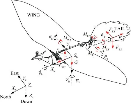
Fig.1 Frames and variables definition.
-:Eodetic coordinate system;-:Body coordinate system;
φ:Roll angle of body relative to-;θ:Pitch angle of body relative to-;
ψ:Yaw angle of body relative to-;φ:Roll angle of tail relative to-;
θ:Pitch angle of tail relative to-;[,,]:Force produced by wings;
[,,]:Moment produced by wings;[,,]:Force produced by tail;
[,,]:Moment produced by tail.
The euler angles and rotation transformation matrices are used to describe the attitude.The following symbols are defined:
R(φ):The rotation transformation matrix from the geodetic coordinate system to the body coordinate system when the body only turns φaround.
R(θ):The rotation transformation matrix from the geodetic coordinate system to the body coordinate system when the body only turns θaround.
R(ψ):The rotation transformation matrix from the geodetic coordinate system to the body coordinate system when the body only turns ψaround.
R:The rotation transformation matrix from the geodetic coordinate system to the body coordinate system when the body turns around the three axes.
These rotation transformation matrices are determined by the following equations:
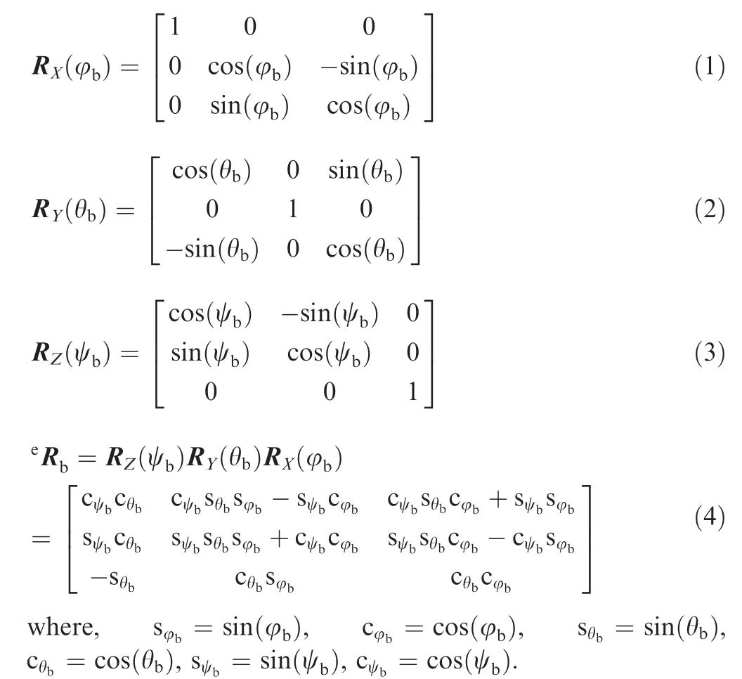
Then,the vector described in the body coordinate systemV and the same vector described in the geodetic coordinate systemV has the following relationship:

2.2.Aerodynamic force and moment analysis
The aerodynamic force and moment are mainly generated by the periodic flapping of wings and the tail during flight.The resultant aerodynamic force and moment will be calculated in the following part.In this part,the aerodynamic performance analysis of flapping-wing is based on the quasi-steady aerodynamic theory and the average theory,aiming to qualitatively analyze the relationship between the aerodynamic force and moment changes with the controllable rudder in HITPhoenix,including the flapping frequency of the wings and the pitching and rolling rudder of the tail.This serves as the theoretical basis for the later controller design.
The wings and tail are made from a light weight polyester cloth and carbon fiber rod.According to the aerodynamic theory of thin airfoil,the lift coefficient Cis calculated as follows:

Then,the aerodynamic force perpendicular to the wing face is determined by:

where ρ is the density of air,represents the aera,is the velocity of incoming flow,α is angle of attack.
The incoming velocityrelated to the flapping speed (frequency) of the wing and the speed of the robotic bird,which are referred by Cfand ‖v‖ respectively,we can calculate the incoming velocityas following.

whereis the flapping frequency of wings,Cis the coefficient convertingto incoming flow velocity,v is flight velocity of the robotic bird.Since the flapping frequency is dependent on the motor speed,the incoming flow velocity changes with that of the motor speed.

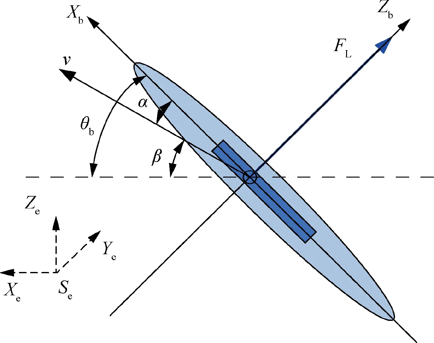
Fig.2 Aerodynamic analysis diagram of wings.

Only when the speed direction of the robotic bird is parallel to the horizontal direction,the angle of attack will be the same as the pitch angle.
Fis the average force generated by the wings relative to the body coordinate during a flapping period.In order to figure outF,it is necessary to project the incoming velocity into the body coordinate,then theFrelated by the incoming flow velocity at this time can be expressed as following.

Similarly,the average forces generated by tail during a flapping period can be approximately calculated as following:
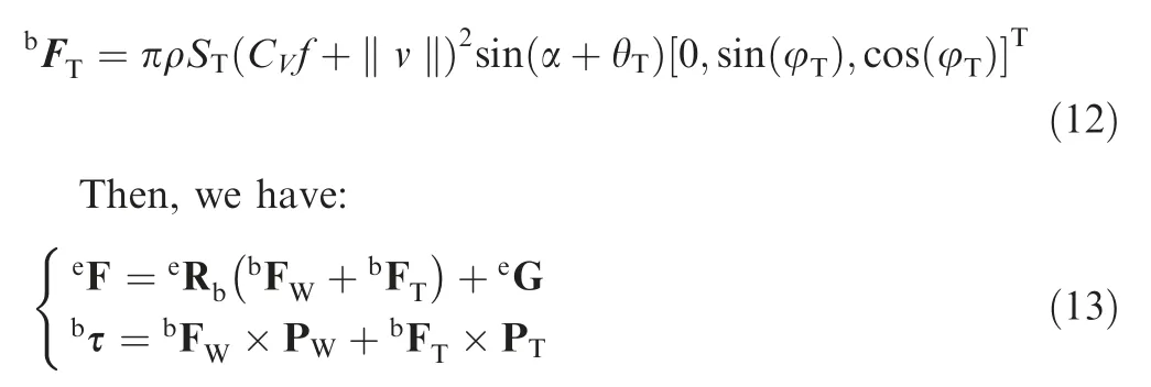
whereF is the resulting force described in the geodetic coordinate system,G is the gravity of HIT-Phoenix described in the geodetic coordinate system,τ is the torque defined in the body coordinate system,Pand Pare respectively the position vectors of the forces generated by the wings and tail.By using the six-axis force torque sensor in the wind tunnel to measure the aerodynamic force generated by the flapping of the prototype’s wings,the range of the aerodynamic center of the prototype under normal flight conditions is obtained.Then,the electronic parts such as lithium battery is designed to be adjustable in installation position or increase the counterweight to adjust the center of gravity of the prototype to make it as close to the aerodynamic center as possible.So,the vector Pis assumed to be the following equation:


According to the structure and mechanism characteristics of HIT-Phoenix,there are three actuators to drive the it,including a brushless motor to control the flapping frequency and two servos to adjust the tail.For convenient description,the motor used for wings’ flapping is denoted as ‘‘Motor”,and the two servos used for the tail are respectively denoted by Servo I and Servo II.The actuators of HIT-Phoenix are shown in Fig.3,where Servo I and Servo II are used to generate the rotation movements of the pitch and roll axes of the tail.
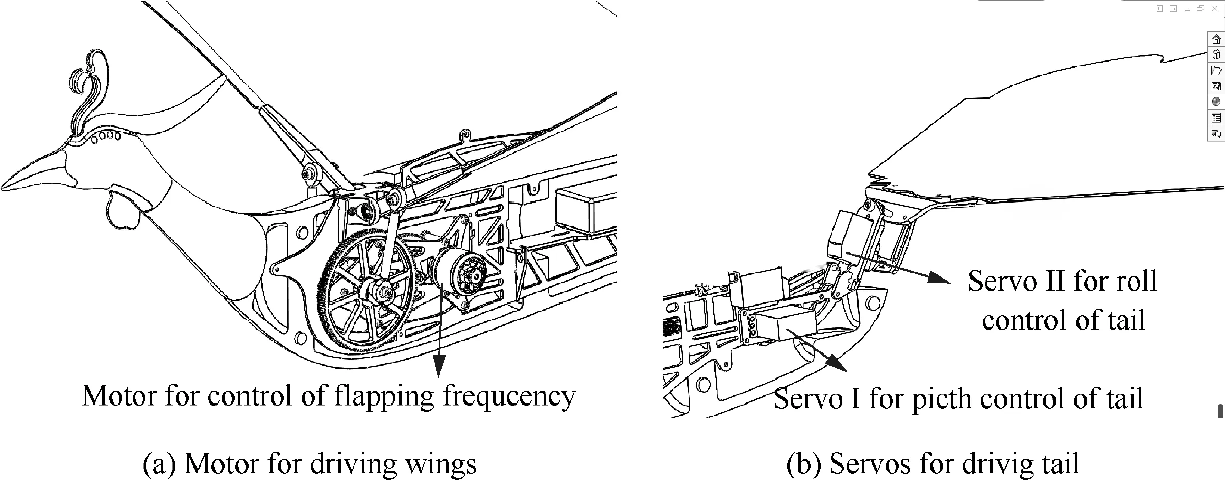
Fig.3 Actuators of HIT-Phoenix.
In order to facilitate the control for the forward flight of HIT-Phoenix,the aerodynamic force generated by the individual motion of each actuator is calculated here,when the other actuators are kept in a reasonable position.
The aerodynamic force produced by wings is calculated first.According to the flight experiments,only a bias of the pitch angle is required to generate the needed aerodynamic force for forward flight when HIT-Phoenix flies in a relatively ideal state.Therefore,the flight control can be simplified for some cases.When the roll angle of body is 0 and the tail surface is parallel to the horizontal plane,the robot flies in the state of force balance.Considering there is a constant bias θof the roll angle of body,the following equations are assumed:

According to the Eqs.(13)-(16),the following results are obtained:

Similarly,the aerodynamic force separately generated by the tail can be determined.The state is shown in Fig.4.where,the pitch angle is denoted by θ.Similar with Eq.(16),the parameters are assumed to be:

Fig.4 Aerodynamic analysis of tail.

Therefore,the following equations can be determined:

If the condition is as follows:
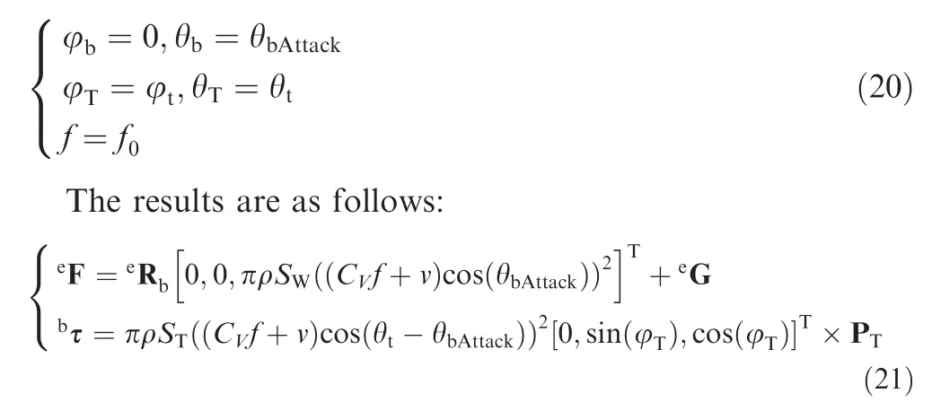
From the dynamics modeling and analysis above,we can conclude the relation between the aerodynamic forces and torque with the movement of each actuators,which is the basis of the controlled design.
3.Autonomous flight control method
According to the mission analysis,the main control tasks of the large-scale flapping-wing flying robot are attitude stabilization and trajectory tracking.Due to relatively low computation ability of the on-board embedded controller,complex control methods are generally difficult to be used.Hence,an autonomous flight control method by combined fuzzy control strategy and Proportion Integration Differentiation(PID)control law is proposed to realize the autonomous flight of the robotic bird.
The control flowchart is shown in Fig.5.The PID control laws are separately designed for each driver to generate the preliminary command for each actuator.Then,the fuzzy control strategy is used to determine the final commands of each actuator according to the fuzzy control rules.In Fig.5,andare the desired commands of Servo I to control the rotation about the pitch axis and hold the altitude respectively;is the combined command of Servo I determined by the fuzzy control.andare the desired commands of Servo II to control the rotation about the roll axis and track the trajectory respectively;S is the combined command of Servo II determined by the fuzzy control.And,is the desired command of motor(the motor to drive the wings flapping) to hold the altitude.
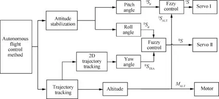
Fig.5 Control system flowchart.
However,the flapping motion consists of two half periods including ‘upstroke’ and ‘downstroke’,and the flapping frequency of wings in our HIT-Phoenix is very low,which can easily cause the control object to oscillate or even diverge using the averaging theory.Therefore,on the basis of the above control system flowchart,the influence of wing flapping angle λ measured by encoder on instantaneous aerodynamic performance is considered in the specific control laws design.Using the experimental method,the equation of aerodynamics with is obtained under the premise of different incoming flow velocity and flapping frequency.
3.1.Attitude estimation
The attitude information is supplied through sensors such as gyros and accelerators.Since each sensor has certain flaws,and it is difficult to obtain the accurate data from a single sensor,a fusion calculation algorithm is designed to fusing the measured values of gyroscope,magnetometer,accelerometer for attitude estimation.Considering the effect of motion acceleration and wing flapping angle on the measured value of the accelerometer,we use the Global Positioning System (GPS)and encoder to compensate it.The process of data fusion is shown in Fig.6.
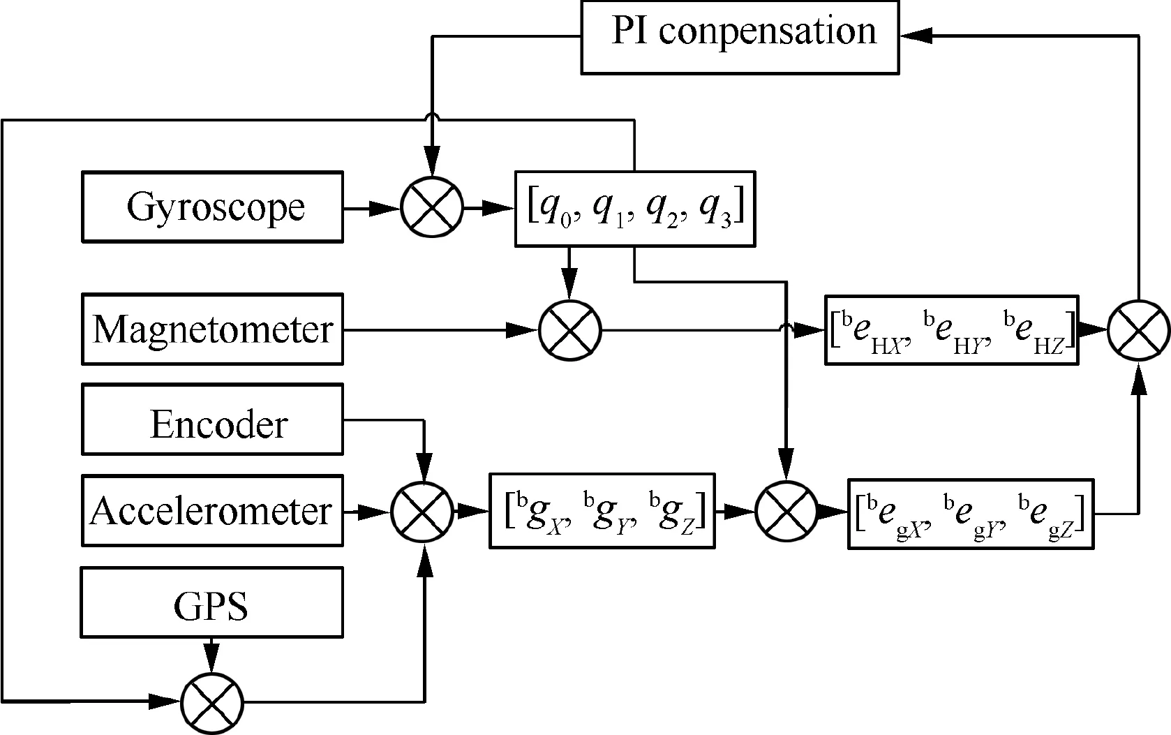
Fig.6 Estimation of attitude.
To avoid attitude singularity and realize global linear resolution during sensors fusing,the quaternion is used to represent the attitude. Correspondingly,the rotation transformation matrix is determined by the quaternion,i.e.:

The derivative of the quaternion is calculated according to the angular velocity measured by the gyroscope,i.e.:

where,ω()is the angular velocity measured by the gyroscope.
Then,the attitude quaternion at each sample time can be updated as follows:

whereis the sampling period of the gyroscope.For the attitude estimation,the initial value of the quaternion is set as[1,0,0,0].
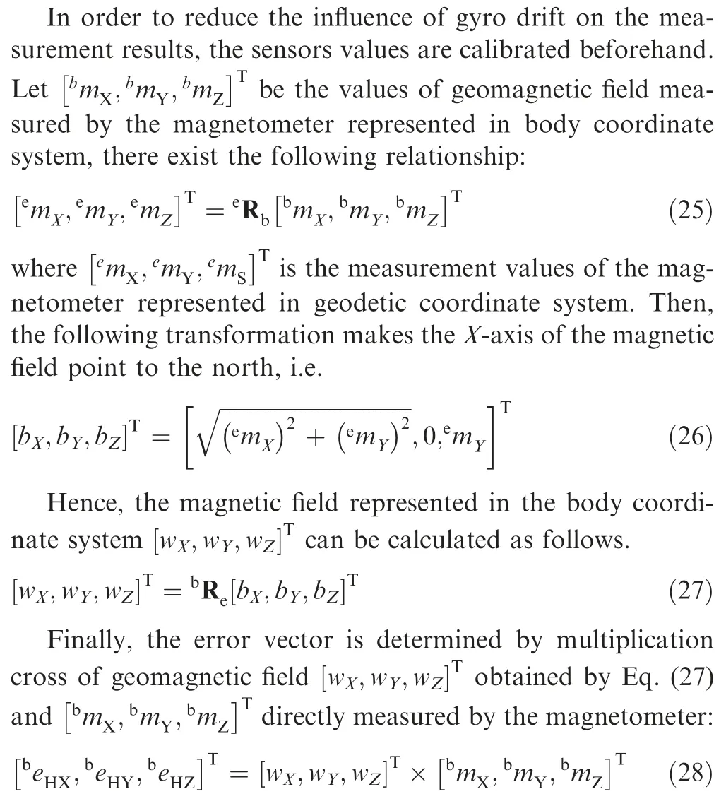
Moreover,the accelerometer can be used to corrected the pitch angle and roll angle.However,the original measurement values include the acceleration of the motion.Here,the GPS to is used to compensate it first.Letaandadenote the acceleration measured by the accelerometer and GPS respectively.(λ) is the function of acceleration and wing flapping angle.The values of the acceleration are corrected by the following equation:
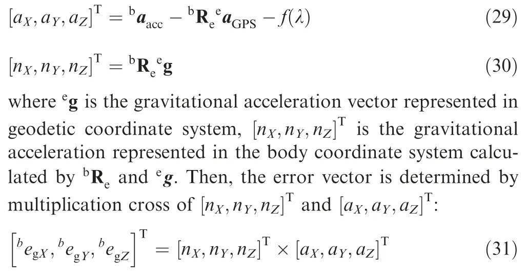
Hence,the total errors of a constant vector measured directly by the magnetometer,accelerometer and values calculated by rotation matrix derived from gyroscope is obtained by adding above two terms from Eq.(28) and (31).
Then the angular velocity ω measured by gyroscope is corrected as follows:

Using the corrected angular velocity ωto update the quaternion by Eq.(23)and(24).Then the attitude angles could be calculated by Eq.(7) and (22) as follows:

Some experiments were carried out to verify the attitude estimation algorithm.The prototype is fixed on the connecting rod of a movable parallelogram mechanism and the wings are controlled to flapping at a certain frequency.The experimental device is shown in Fig.7.
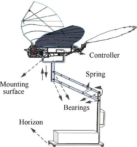
Fig.7 Experimental platform for attitude estimation test.
The results are shown in Fig.8,the red dotted line represents the real pitch angle.We can find that there is no large drift and jump in calculated results considering wing flapping angle,while the estimated attitude fluctuates greatly due to a large change in the instantaneous aerodynamic force without considering wing flapping angle.The estimated results prove the validity of the proposed algorithm.
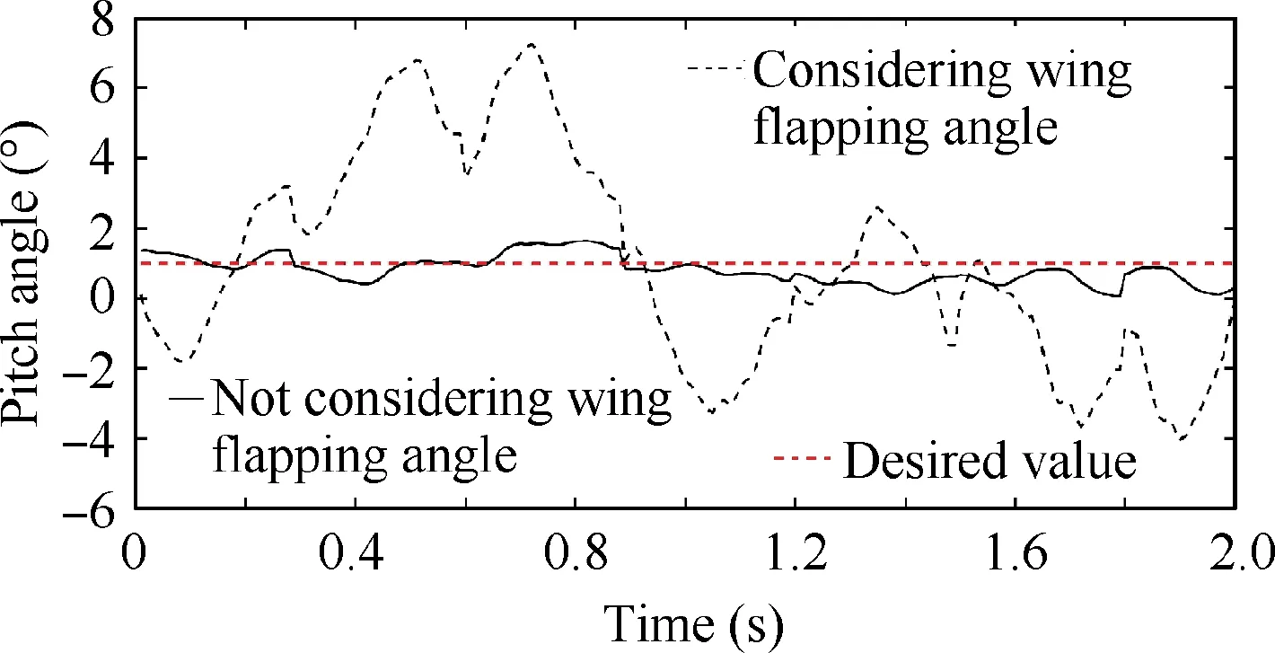
Fig.8 Experimental results of attitude estimation with considering wing flapping angle and not.
3.2.Attitude stabilization control
The cascade PID controllers are designed for attitude control with relative high control accuracy and response speed.The control flowchart of the pitch angle is shown in Fig.9.

Fig.9 Cascade PID controller of pitch angle.
There are two PID controllers in series,i.e.Angle PID and Speed PID.The desired pitch angle is denoted by θ.It is the sum of θand θ.The former (i.e.θ) is the expected angle of attack to get enough lift and the latter (i.e.θ)is the pitch command sent through the remote controller.For the autonomous flight mode,θ=0.For the manual control mode,θis determined by the operator.The output of the angle PID controller is the expected angular velocity for the speed PID controller;it is denoted by ω.Considering that the wing flapping angle has great influence on instantaneous pitching moment,λ is added in the controller of pitch angle.Feedback information is denoted by θand ωrespectively,they are supplied by the attitude fusing algorithm.
The stabilization control for roll axis is similar with that of pitch axis.The control flowchart is shown in Fig.10.

Fig.10 Cascade PID controller of roll angle.
3.3.Trajectory tracking control
The trajectory tracking problem is divided into two subproblems:two-dimensional trajectory tracking in a plane(called plane trajectory tracking) with a certain altitude,and altitude tracking to attain the desired altitude.
The desired trajectory is autonomously planned according to the mission requirement or supplied through the ground devices (remote controller or ground station).It is then described as multiple motion nodes,which are called waypoints.The purpose of control is to make the robot follow these waypoints step by step along the desired direction.The waypoint closest to the current position is first determined and taken as the current desired waypoint.Then,the controller will generate the command according to the difference between the current position and desired waypoint.In order to illustrate the details,two typical trajectories -linear and circular trajectories tracking control will be introduced in the following.The tracking strategy of linear trajectory is shown in Fig.11.
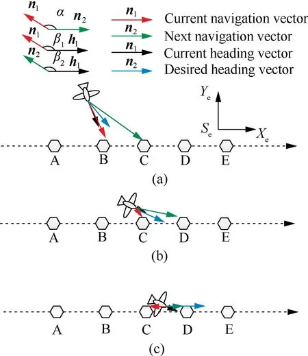
Fig.11 Linear trajectory tracking strategy.
The dotted lines represent the target trajectory and the letters‘‘A,B,C,...” denote the planned waypoints.The red letter is the current waypoint and the green letter is the next waypoint.Other symbols are defined as follows:nis the current navigation vector from the current position to the current waypoint;nis the next navigation vector from the current position to the next waypoint;his current heading vector and his desired heading vector;α is the angle betweenand:>n2;βis the angle between nand h;βis the angle between nand h.The above angles are limited to-180-180.
The desired heading vector his determined according to the relationship between direction of vectors n,nand h.There are three cases as follows.(1) When α ≤90and abs(β-β)=α,his along the angular bisector of α,shown as Fig.11(a).(2) When α ≤90and abs(β-β)<α,his along h,shown as Fig.11(b).(3) When α >90,his along n,shown as Fig.11(c).
The tracking strategy of circular trajectory is similarly with that of the linear trajectory after the way points are determined according to the characteristics of the circular motion,where the position and velocity are constrained simultaneously.The control process is shown in Fig.12.
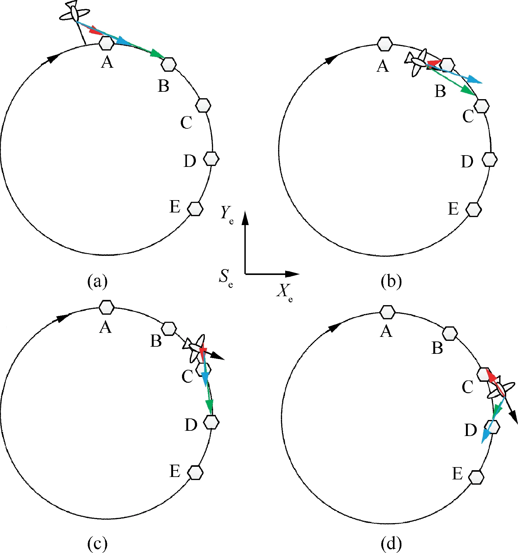
Fig.12 Circular trajectory tracking strategy.
Then,the trajectory tracking controller is designed based on the strategy above.The control flowchart is shown in Fig.13.

Fig.13 Trajectory tracking controller.
The altitude control is relatively simple.When the desired and current values are determined,a PID control law is used to generate the command for the Motor to flap the wings and command to control servo I according to Eq.(19).The control flowchart is shown in Fig.14.

Fig.14 Altitude controller.
3.4.Fuzzy controller
Based on the previous analysis,we can find there are strong coupling of force and motion for FWAV,Control method based on human manipulation experiencecan be applied in this study.Fuzzy control is an intelligent control method based on fuzzy set theory,fuzzy language variables and fuzzy logic reasoning.Relying on human knowledge and experience,many control problems that cannot get the accurate plant model were solved through fuzzy control method.According to the previous analysis,the final command of Servo I is mixed with the command of pitch angle and altitude controllers,and the final command of Servo II is mixed with the command of roll angle and 2D trajectory tracking controllers.For the realization,the weighting coefficients are used to represent the effect of different controller commands and the mixed equations are as following:

where,,andare the weighting coefficients concerning about pitch stability,altitude tracking,roll stability and trajectory tracking respectively;andis the final command of Servo I and Servo II separately.
Then,the fuzzy control algorithm is designed to determine the weighting coefficients based on the experience of human manipulation.Since the primary control task of HITPhoenix is to make attitude remain stable,three membership functions are established.They are respectively attitude angle,pitch angle and roll angle.Without loss of generality,these membership functions are assumed as triangular and symmetric.For pitch and roll angles,the inputs to fuzzy algorithm are seven values.They are defined as Pitch Very Dangerous(PVD),Pitch Little Dangerous (PLD),Pitch Little Stable(PLS),Pitch Very Stable (PVS),Roll Very Dangerous(RVD),Roll Little Dangerous (RLD),Roll Little Stable(RLS),Roll Very Stable (RVS).The values corresponding to pitch and roll angles are shown in Fig.15 and Fig.16 respectively.
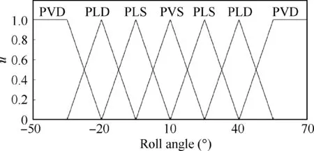
Fig.15 Fuzzy membership function of pitch angle.
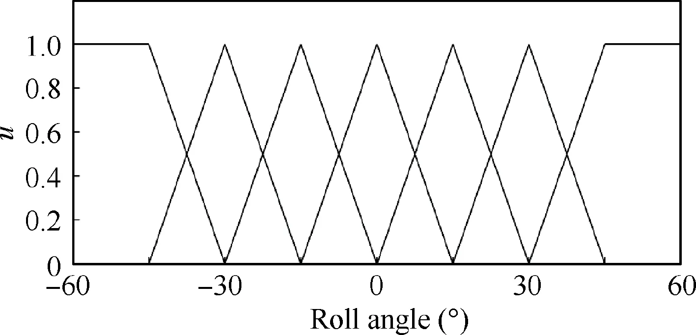
Fig.16 Fuzzy membership function of roll angle.
The fuzzy rules are defined according to many practical flight experiments,which were carried out by manual control.According to the experiment results,when the absolute value of attitude angle is too large,the prototype is in a dangerous state and the flight is prone to instability and fall.Hence the attitude must be adjusted first.Then,trajectory tracking performance is required to be assured.Considering the above factors,the rules of the fuzzy control are defined as follows.
Rule 1:if pitch angle is PVD,then=0.8,=0.2.
Rule 2:if pitch angle is PLD,then=0.7,=0.3.
Rule 3:if pitch angle is PLS,then=0.6,=0.4.
Rule 4:if pitch angle is PVS,then=0.5,=0.2.
Rule 5:if roll angle is RVD,then=0.8,=0.2.
Rule 6:if roll angle is RLD,then=0.7,=0.3.
Rule 7:if roll angle is RLS,=0.6,=0.4.
Rule 8:if roll angle is RVS,=0.5,=0.5.
These rules are then applied to determine the weighting coefficients.Correspondingly,the final commands of servo I and servo II are calculated according to Eq.(34).It should be pointed out that,the maximum of,,,and,are limited as the maximum amplitudes by considering the practical constraints on the motor and servos.
4.Flight control system
In order to realize the autonomous flight control with high efficiency,the proposed control method should be programed and run on an on-board embedded controller.Taking into account safety,reliability and flexibility for different requirements,semi-autonomous control and manual control functions should also be provided for the operator.Therefore,a global control system was developed to simultaneously meet autonomous,semi-autonomous and manual flight control requirements.The system development will be detailed in the following part.
4.1.Control system structure
The global control system of HIT-Phoenix is composed of the on-board controller,ground devices and communication link.The ground devices include a remote controller and a ground station.The structure of the whole control system is shown in Fig.17.
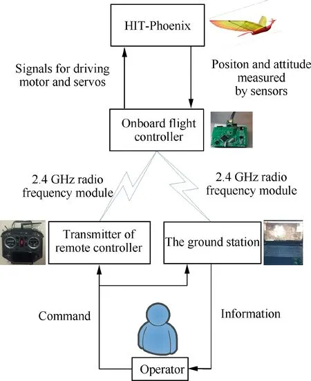
Fig.17 Structure of the global control system.
The autonomous and manual control are respectively realized by the on-board flight controller and the remote controller.For the semi-autonomous control,it is actually a hybrid control mode combined by partly manual and partly autonomous control.That is to say,some flight states are controlled by manual and others are autonomously controlled by the onboard flight controller.
The onboard flight controller communicates with the remote controller and the ground station through 2.4 GHz radio frequency module.The operator can send the command to set the flight mode or change the desired position and attitude of HIT-Phoenix through either or both the remote controller and ground station.The flight data including actual position and attitude is also transferred back to the ground station.The remote controller has the highest priority.It can take over the control and directly manage the signals for driving the motor and servos.
4.2.On-board embedded flight controller
The on-board embedded flight controller is installed on the fuselage of the robot and runs the autonomous flight control algorithm.The design of its hardware and software will be detailed in the following part.
The hardware of the flight controller includes sensors,power source and Micro Controller Unit (MCU).The hardware structure of the flight controller is shown in the Fig.18.
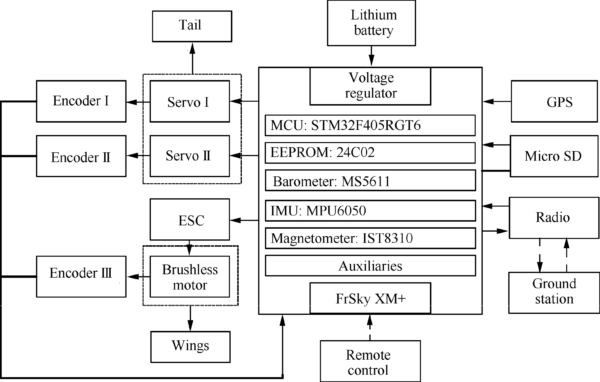
Fig.18 Hardware structure of the flight controller.
The Micro-Electro-Mechanical System (MEMS) sensors such as gyroscope and accelerometer are used to measure the flight status while ensuring that the area of the board is small enough to implement the airborne solution.The GPS with the ceramic antenna is designed as an external module to ensure the signal receiving strength.Three encoders are used to supply the feedback information for the closed-loop control of the three actuators.They are all absolute encoders and are denoted by Encoder I-III.The two encoders,i.e.Encoder I and Encoder II are installed near the servos and used to measure the pitch angle and roll angle of the tail.Encoder III is installed near the brushless motor and used to measure the flutter position and frequency of the wings.
The power source used for HIT-Phoenix is lithium polymer battery made by GREPOW.The normal voltage is 11.1 V.Its capacity is 800 mAh.The maximum continuous discharge current is 12 A.
The main processor of the MCU is STM32F405RGT6.It has rich peripheral resources,including high-speed embedded memories and several standard communication interfaces.It has Floating Point Unit (FPU) and the frequency reaches 168 MHz,making it can process large number of data and output control instructions at high speed.The raw data of various sensors including Inertial Measurement Unit(IMU)barometer magnetometer and GPS are fused to supply more accurate measurement results.Micro SD card are used to store the configured parameters and the log files respectively.The configured parameters include the gains of PIDs and calibration values of sensors.The log files record the historical operating status data,including the raw date of sensors and fused results.The receiver of remote command is the product of FrSky XM PLUS.It can receive 16 channels of transmitter through only one line according to protocol of Serial Bus (S.BUS).The radio of 2.4 GHz is chosen to communicate with onboard controller.The operator can tune the parameters and plan the desired path remotely.The MCU output three Pulse Width Modulation (PWM) signals to the two servos and the motor.Detailed specifications of the sensors are listed in Table 1.
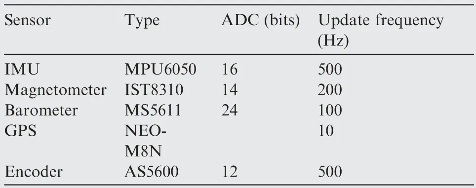
Table 1 Specifications of sensors.
All the above components are integrated to a circuit board.Its size is 5.8 cm long and 4 cm wide.The total mass is 11 g.The circuit board of the controller is shown in the Fig.19.
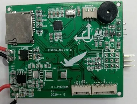
Fig.19 Circuit board of the onboard flight controller.
The flight control software is developed based on FreeRTOS,a widely used embedded and open source real-time operating system.It can help us schedule tasks to improve the operating efficiency.The application software consists of sensors’driving and task execution modules.The structure of the flight control software is shown in Fig.20.
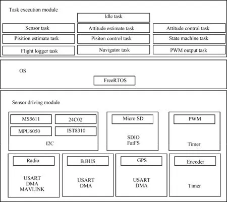
Fig.20 Structure of the flight control software.
The sensor driving module achieves the protocol of reading or writing chip’s data including I2C,SDIO and so on.When the USART related devices are driven,Direct Memory Access(DMA) is used to transport the data.This design reduces the Central Processing Unit (CPU) load,because using serial port to transfer large amounts of data usually spends a lot of time.The sensor driving module will provide the API of operating hardware,then the task execution module can call these interfaces to implement the required function without considering the practical hardware.FreeRTOS stipulates that each task should be given a priority;the higher the priority of the task,the more it can obtain the right to use the CPU.Idle task of FreeRTOS has the lowest priority.For the flight control,the PWM output related sensor driving tasks have higher priority than other sensors.Moreover,different tasks also have been set an operating frequency.For example,the operating frequency of attitude control task is set as 500 Hz,while flight logger task is set 250 Hz.The flow char of software is shown in the Fig.21.The CPU occupancy rate is below 50% during normal operation,meaning that the software can run stably as expected and has a certain scalability.
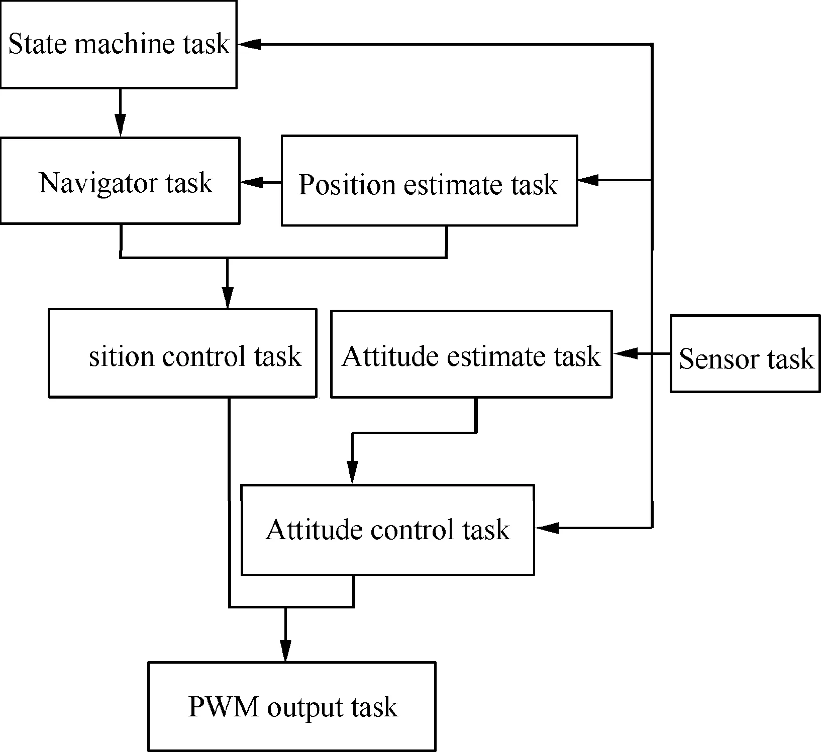
Fig.21 Logical flow chart of software.
4.3.Ground devices
The ground devices consist of a remote controller and a ground station.The transmitter of remote controller is the product of FrSky,Horus X10S.It communicates with the onboard flight controller through 2.4 GHz radio frequency module.It can transmit 16 channels.The function definition diagram of channels is shown in Fig.22.

Fig.22 Remote controller and its function definition diagram.
The operator can modify the flight mode with the rocker in the green area.The flight control parameters can be adjusted through rotary knob in the blue aera.The joysticks in the red aera can be used to change the expected value of flight such as altitude and attitude.In addition,a special flight mode is designed to handle the case of sensor failure.In this mode,the output of the joystick can be mapped directly to the commands of the actuators.This design allows the ground operator to directly replace the onboard controller and take over the control of the flying robot.
The ground station is another important part of the global control system.It can be used to carry out the calibration of the devices such as sensors,remote transmitter and Electronic Speed Control(ESC)before practical flight.It can also be used to determine the flight mission and plan the waypoints for autonomous flight.
During the flight,the onboard controller transmits the flight data to the ground station through digital radio.The flight data are used to display its current status and flight history on the ground station.Therefore,the ground operator knows the on-board status in real time.In addition,the control parameters of onboard devices and the flight mode of the robot can be modified through the ground station.There are some mature ground stations for drones,such as QGround-Control and MissionPlanner.QGroundControl has perfect function and good man-machine interaction interface,in addition,it can run on Windows,Linux platforms,IOS and Android devices.So,we choose it as the basic platform for secondary development.We add a new airframe configuration for HIT-Phoenix and the parameter configuration interface is also simplified as needed.The developed ground station is very light and easy to carry.The photographs of QGroundControl are shown in Fig.23.
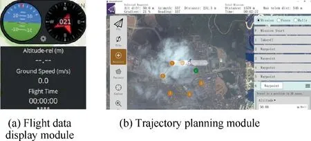
Fig.23 Photographs of QGroundControl.
5.Flight experiment and demonstration
5.1.HIT-Phoenix phototype
The HIT-Phoenix developed by our team is shown in Fig.24.Its performance parameters are listed in Table 2.The onboard flight controller mounted to the HIT-Phoenix is shown in Fig.25.The main parameters of the flight controller are listed in Table 3.
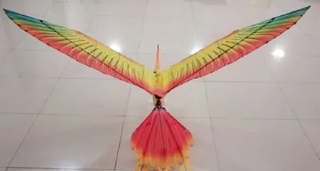
Fig.24 Photographs of HIT-Phoenix.
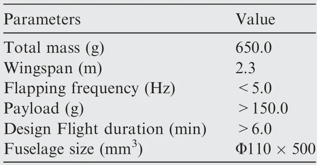
Table 2 Parameters of HIT-Phoenix.

Table 3 Parameters of flight controller.

Fig.25 Flight controller is equipped on the HIT-Phoenix.
5.2.Flight experiments of single robotic bird
In order to verify the developed control system,many flight experiments were verified.The main experiment types include manual control,semi-autonomous control and autonomous control.
For the manual flight experiment,the flying bird is required to take off,fly straightly,change flight direction and altitude by the operator.The attitude data during flight are shown in the Fig.26.
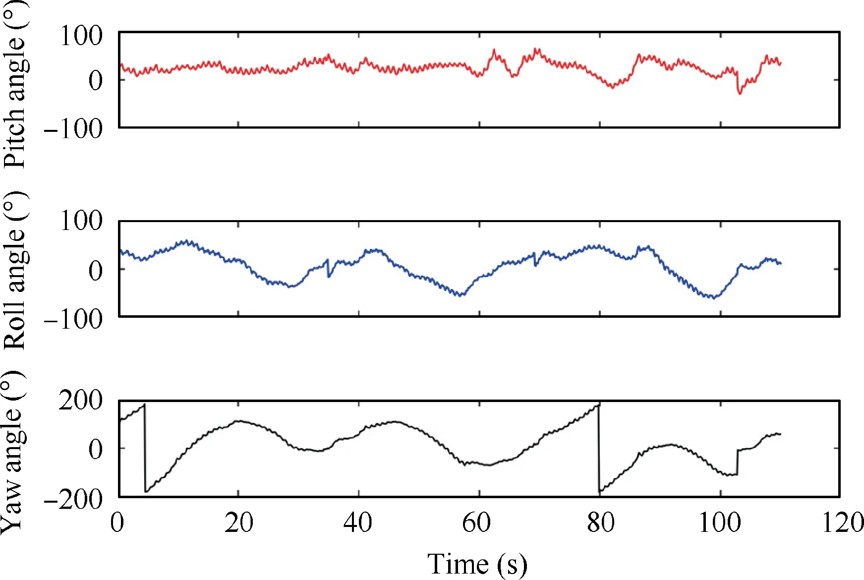
Fig.26 Attitude data changes with time using manual control.
We can find that attitude angles vary within a large range.The variation range of both pitch and roll angles exceeds±50,which means that the flight of the prototype is not very stable.This is because that the manual operation subject to the limits of user’s experience,and the command from the operator to the flying robot is delayed.The result of this experiment explains the necessity of autonomous flight control.
For the semi-autonomous flight experiment,the flying robot is required to achieve roll and pitch stabilization by autonomous flight control while adjusting the altitude by manual.The attitude data during the flight experiment is shown in the Fig.27.
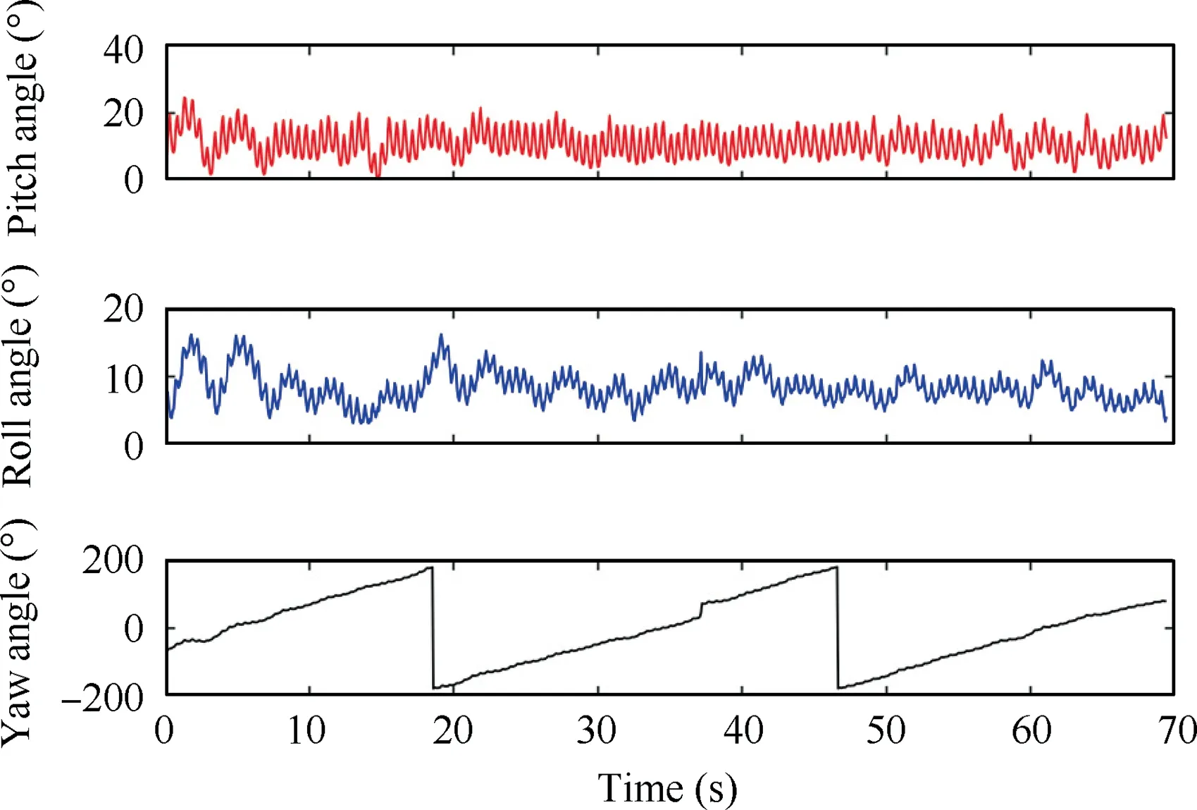
Fig.27 Attitude data changes with time using semi-autonomous control.
The variation ranges of the pitch and roll angles are within 10 degree.The altitude adjustment during the experiment is shown in Fig.28.The flying bird flied from about 30 to 50 m by manual.
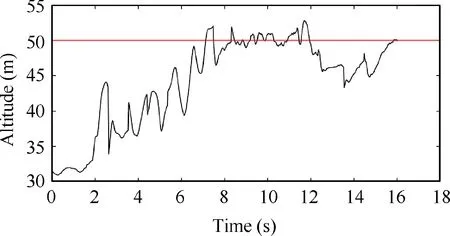
Fig.28 Altitude data changes with time using semi-autonomous control.
Finally,a take-off and trajectory tracking flight experiment are carried out to verify autonomous flight control.The robot is required to take off autonomously when the operator throws the it diagonally up.Then it flies to track the desired circular trajectory and altitude.The flight process is shown in Fig.29.
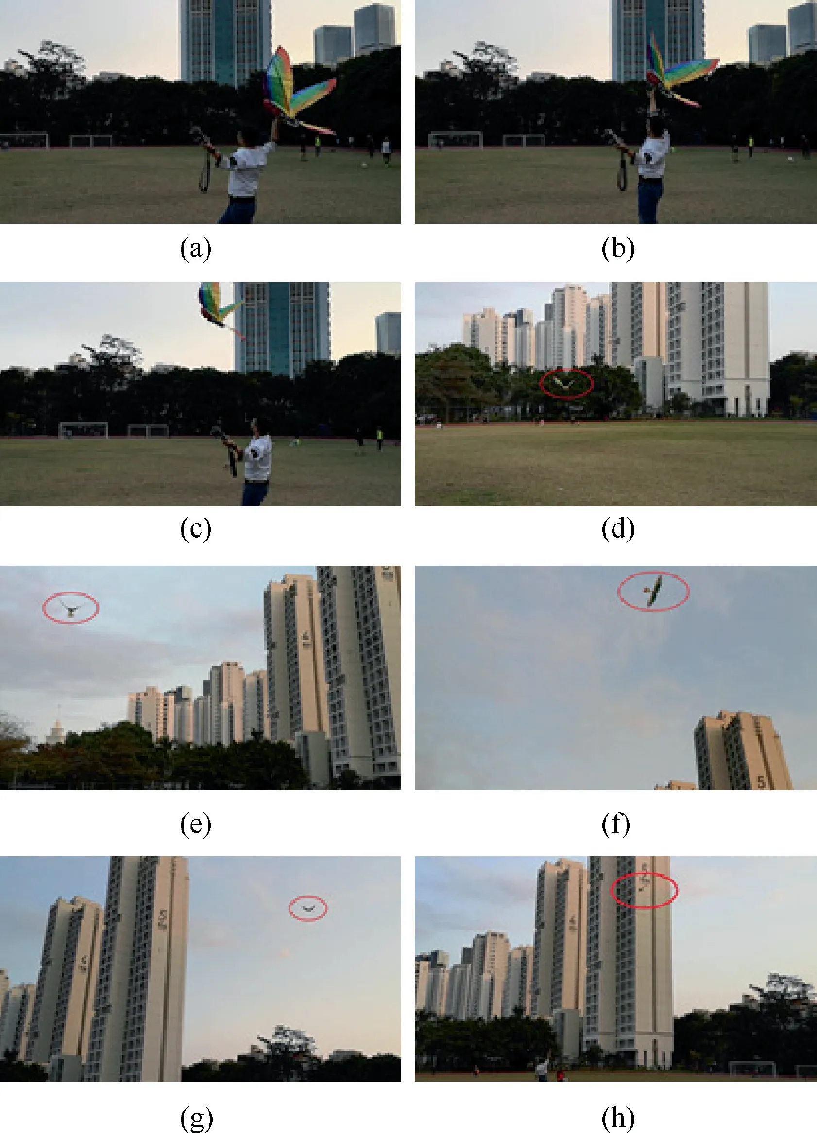
Fig.29 Flight process using autonomous flight control.
The experiment show that the operator just needs to throw it obliquely upwards horizontally.When the measured value of acceleration along the-axis was greater than the critical value,its flapping frequency of wings quickly reached the trimmed value,and the tail was also adjusted to stabilize itself and track the desired trajectory.To present the performance of the controllers designed in this paper,we apply PID controllers to this trajectory tracking experiment,comparing the experiment results of proposed method with PID control as shown in Fig.30.
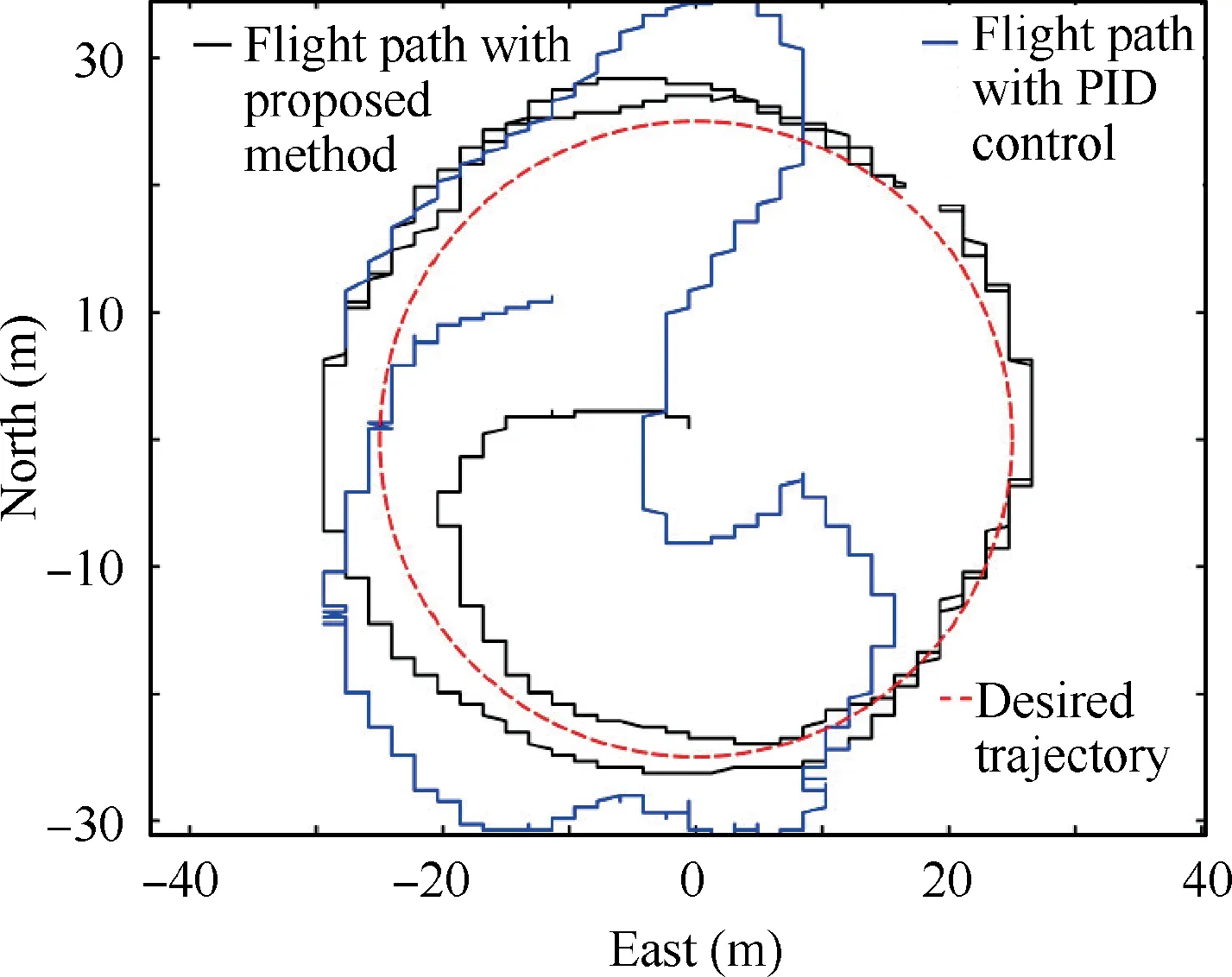
Fig.30 Circular trajectory tracking of HIT-Phoenix using autonomous flight control.
We can clearly find that the control accuracy of the proposed method PID cascade control with fuzzy control is much higher than that of the PID controller.
Then,we analyzed flight control performance under different experimental conditions such as sunny and windy weather,which means wind speed is different.Since we conduct flight experiments outdoors,the flight conditions are uncontrollable.Therefore,we measured the wind speed while we were doing experiments to study the influence of the experimental conditions such as sunny and windy weather on the experimental results while other experimental conditions remain the same as in the previous experiment.The wind speed measuring device was built as shown in the Fig.31 to measure the wind speed during the experiment.
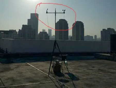
Fig.31 Wind speed measuring device.
The influence of weather conditions on the experimental results is shown in the Fig.32.When the wind speed is less than 5 m/s,the tracking error does not change much as the wind speed increases;when the wind speed continues to increase,the tracking error increases sharply.This is because the ability of wind resistance of the prototype is limited.
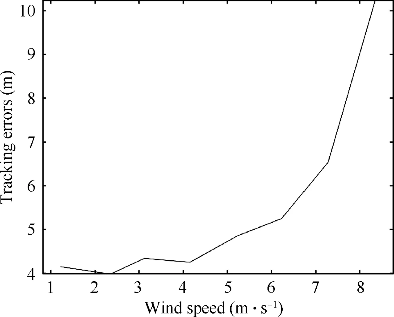
Fig.32 Circular trajectory tracking of HIT-Phoenix using autonomous flight control.
The causes of errors in the experiment are analyzed as following.First,the current prototype is only driven by three actuators—one for wings flapping and two for tail adjustment,the flight attitude and trajectory are highly coupled,it has limited controllable degree of freedom and insufficient maneuverability.Second,prototype use a simple single-link flexible wing means the Insufficient aerodynamic performance,and the larger wingspan makes it more vulnerable to wind.Hence,excessive external interference such as a large gust will affect the flight control accuracy of the prototype.Finally,the acquisition delay and fusion precision of the sensor also affect the control precision.
The following strategy can be carried out to reduce errors.First,the driving mechanisms of such type of flying bird will be improved by adding more degrees of freedom.Second,the wings should be optimized for better maneuverability.Finally,better sensors and fusion methods can be used to achieve higher accuracy.
6.Conclusions
A flight control system was specially developed for a largescale flapping wing robotic bird to realize autonomous,semiautonomous and manual control modes.The flight experiments verified the reliability of the developed control system.Since the current prototype is only driven by three actuators—one for wings flapping and two for tail adjustment,the flight attitude and trajectory are highly coupled.Hence the control ability is very limited and the control accuracy is relatively low.The current work is mainly to achieve high reliability and stable flight.In the future,the driving mechanisms of such type of flying bird will be improved by adding more degrees of freedom.For example,the two wings are respectively driven by separated actuator;each wing can be folded or retracted by another motor.Correspondingly,the control ability will be largely improved.Advanced control methods will be then developed to realize flight performance with higher accuracy and higher flexibility.
The authors declare that they have no known competing financial interests or personal relationships that could have appeared to influence the work reported in this paper.
This work was supported by the National Natural Science Foundation of China (No.U1613227,61803125),Guangdong Special Support Program of China(No.2017TX04X0071),and the Basic Research Program of Shenzhen of China (Nos.JCYJ20180507183610564,JCYJ20190806144416980).
 Chinese Journal of Aeronautics2022年2期
- Chinese Journal of Aeronautics的其它文章
- Pressure-induced instability and its coupled aeroelasticity of inflated pillow
- Adjoint boundary sensitivity method to assess the effect of nonuniform boundary conditions
- Transit time difference and equal or non-equal transit time theory for airfoils with lift
- A boundary surrogate model for micro/nano grooved surface structure applied in turbulence flow control over airfoil
- Nonlinear uncertainty quantification of the impact of geometric variability on compressor performance using an adjoint method
- High precision and efficiency robotic milling of complex parts:Challenges,approaches and trends
