Theoretical model and testing method for ball indentation based on the proportional superposition of energy in pure elasticity and pure plasticity
Shuqin SI ,Lixun CAI,* ,Hui CHEN ,Chen BAO ,Xiokun LIU
a Applied Mechanics and Structure Safety Key Laboratory of Sichuan Province,School of Mechanics and Engineering,Southwest Jiaotong University,Chengdu 610031,China
b School of Civil Engineering,Changsha University of Science &Technology,Changsha 410114,China
KEYWORDS Ball indentation;Energy density;Proportional superposition of elasticity and plasticity;Stress vs.strain relationships;Testing method;Theoretical model
Abstract For a homogeneous,continuous,and isotropic material whose constitutive relationships meets with the Ramberg-Osgood law (R-O law),the energy in the elastoplastic indentation with a ball indenter was theoretically analyzed,and the proportional superposition of energy in pure elasticity and pure plasticity during indentation was considered based on the equivalence of energy density.Subsequently,a Proportional Superposition-based Elasto Plastic Model (PS-EPM) was developed to describe the relationships between the displacement and the load during the ball indentation.Furthermore,a new test method of Ball Indentation based on Elastoplastic Proportional Superposition (BI-EPS) was developed to obtain the constitutive relationships of R-O law materials.The load-displacement curves predicted using the PS-EPM model were found to agree closely with the Finite Element Analysis (FEA) results.Moreover,the stress vs.strain curves predicted using the BI-EPS method were in better agreement with those obtained by FEA.Additionally,ball indentation was performed on eleven types of metal materials including five types of aluminum alloys and six types of steel.The test results showed that the stress vs.strain relationships and the tensile strength values predicted using the proposed BI-EPS method agreed well with the results obtained using conventional uniaxial tensile tests.
1.Introduction
A material’s mechanical behavior is determined by fundamental relationships (e.g.,the stress vs.strain relationships) and performance indicators (e.g.,yield strength and tensile strength),which are usually obtained through uniaxial tensile tests.However,the difficulty with performing standard tensile tests on in-service structures and small-volume materials has led to the increasing importance of micro-destructive miniature indentation testing.This method uses a ball,conical,or cylindrical indenter to indent a specimen with a continuous load.The stress vs.strain relationships and strength properties of the sample material may then be calculated from the test load versus depth () curve.Fig.1(a) and 1(b) illustrate the loading of a ball indenter with a diameteron a material and the corresponding indentationcurve;andare the contact radius and contact depth,respectively.Acurve includes loading and unloading segments with,,andbeing the load,displacement,and unloading stiffness,respectively,of the material at the instant of unloading;is the displacement that corresponds to unloading the load to 0.
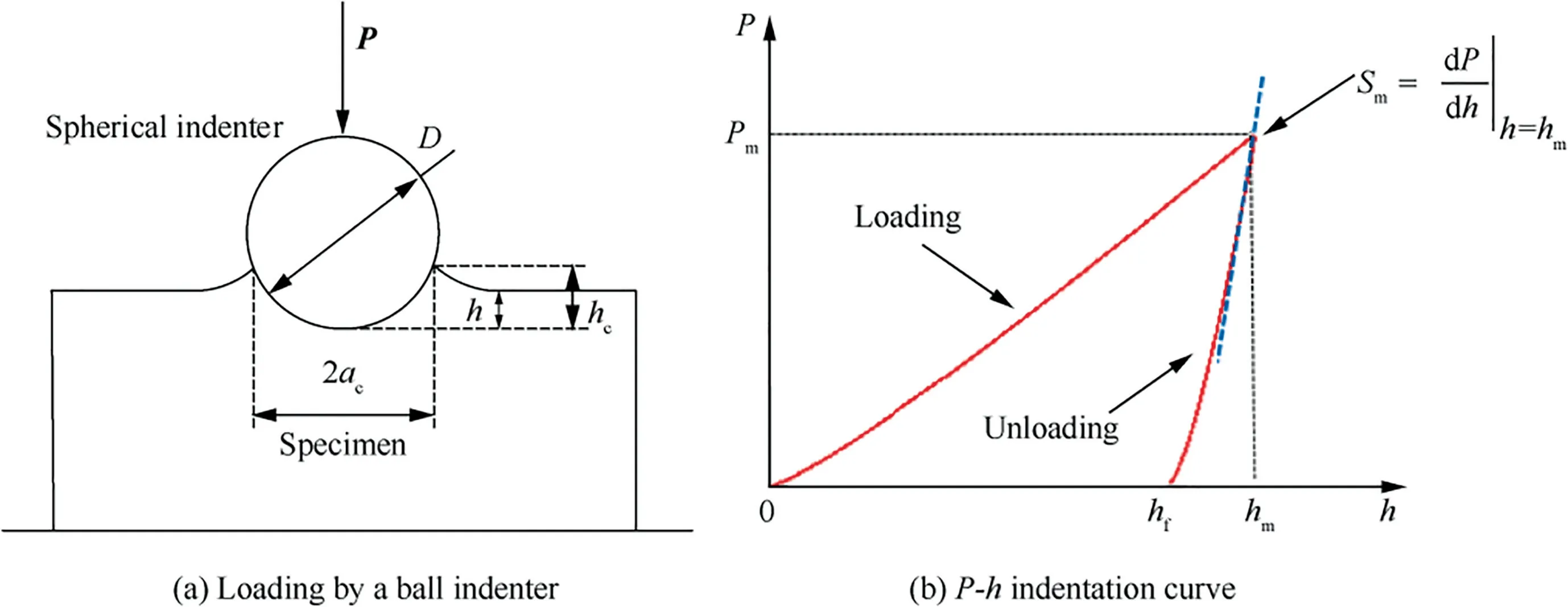
Fig.1 Ball indentation.
In 1948,Tabor proposed the ball indentation methodto determine a material’s mechanical properties indirectly from theindentation curve.Because a non-rigid indenter weakens the unloading stiffness of acurve,the reduced moduluswas defined to characterize this effect:

wherevandare the Young’s modulus and Poisson’s ratio,respectively,of the specimen andandare the Young’s modulus and Poisson’s ratio,respectively,of the ball indenter.In 1961,Stilwell and Taborproposed thatis proportional tobut inversely proportional to the effective area of contactbetween the ball indenter and specimen at the instant of unloading(=).In 1987,Kingintroduced the shape correction factor β to account for the small effect of the indentation shape on the indentation results:

Here,the subscripts c and m indicate the instants of contact and initial unloading,respectively;is the contact radius,is the contact depth,andis the diameter of the indenter.Seven years later,Hendrixascertained that the Berkovich,Vickers,and cylindrical indenters have β values of 1.034,1.012,and 1,respectively.In 1992,Oliver and Pharrassumed that the initial unloading segment of thecurve is welldescribed by a power law relation,and proposed an empirical equation that relates the contact depthto the indentation depth at the unloading pointand initial unloading stiffness:=-0.75/.Eq.(2) may then be expressed as

whereandare constants.A β value for ball indenters was not defined by Hendrixand is not available in the ASTM 2546and GB/T 22458standards.Thus,Zhang et al.proposed a parabolic relation between β and/for macroscopic ball indentation and provided loading/unloading methods to determine β according to the GB/T 37782-2019 standard.This was based on the observation that β is always proportional to/when ball indenters are loaded/unloaded on various steels.
In 1989,Hill et al.proposed an analytical solution for ball indentation in ideal elastoplastic specimens.However,this solution does not apply to indentation tests on power-law materials.To sidestep the material-related limits of Hill et al.’s solution,Haggag et al.used Tabor’sdefinitions of the stress and strain that represent the deformed zone(i.e.,the representative stress σ(true stress)and representative strain ε(true strain)).They then hypothesized that σis proportional to the mean contact pressure over the projected area of indentation impression,and εis proportional to a dimensionless geometric parameter of the indentation impression.Haggag et al.then provided empirical proportionality constants for σand εto propose the automatic ball indentation,where σand εare obtained from multiple indentation cycles.Kwon et al.redefined σand εby supposing that a representative unit exists within the deformed zone of the loaded material whose σand εvalues are proportional to the mean pressure of the contact surface/and the shear strain at the contact edge/(/2-).Both the Kwon and Haggag methods require multiple cycles of indentation to obtain a sufficient number of(σ,ε)data points.Although the Kwon definitions of true stress and true strain are somewhat more straightforward than the Haggag definitions,the proportionality coefficients of the former are obtained by averaging the results of Finite Element Analysis (FEA) for many types of materials.Therefore,the Kwon method is empirical with intrinsic errors.Because precisely measuring the initial unloading stiffness is a challenge for shallow indentations in macroscopic ball indentation,obtaining the true stresses and true strains of indentations with a small initial plasticity is difficult via conventional multiple-indentation methods,which are invariably based on the representative stresses and strains.Therefore,the Haggag and Kwon methods are better suited to deep indentation.In 2004,Cao and Luconstructed an empirical function that relates the dimensionless function Π(comprising the load,indentation depth,and representative stress σ) to the dimensionless representative stress σ/(whereis the characteristic stress) based on a dimensional analysis proposed by Cheng Y and Cheng C.The plasticity parameters of Hollomon’s law (i.e.,σand) may then be obtained through the reduced modulus and two indentation depths determined via indentation loading tests.This method has the advantage of only requiring the loading displacement and not the unloading displacement.However,the fitting equation for σ(Π=/σ=[ln(σ/)])is difficult to calculate because each depth includes multiple sets of fitting parameters;this limits the applicability and accuracy of this method.In 2017,Dean and Clyneproposed an FEA-based approach for obtaining the constitutive relations of a material.A single run of ball indentation data is compared to a library consisting of thousands of FEA-generated ball indentation load-displacement (curves);the constitutive relations of the FEAcurve that best correlates with the experimentalcurve are then selected as the material’s constitutive relations.However,the solutions produced by this inverse approach are not unique.In 2006,Beghini et al.expanded the dimensionless load/into a mathematical series consisting of four terms.They then expanded each term coefficient into 36 terms related to the limit of proportionality stress and strain-hardening coefficient.This gives the equation 144 constants,which can then be obtained by least squares fitting to a large number of FEA curves.The Beghini method is similar to the Clyne method;the only difference is that it uses a complex equation with 144 parameters to replace the library of FEAcurves in Clyne’s method.Similarly,the inverse approach of Beghini does not produce unique solutions.
In 2019,Chen et al.proposed a semi-analytical model for ball indentation that is based on the equivalence of energy density principle,which was used to develop a method for obtaining the stress vs.strain relationships,tensile strength,and Brinell,Rockwell,and Vickers hardness values of a material from experimentalcurves.This method can be used to obtain the stress-strain relationships and material constants with a high level of accuracy.However,it neglects the initial elastic strain energy in the energy equation.Corrections have been made to improve the accuracy;nonetheless,the description of the initial elastoplastic stage by the load-displacement equation still contains varying levels of error.
This paper developed a semi-analytical model for ball indentation displacement-load curves that is based on the equivalence of energy density principle and proportional superposition of pure elasticity and pure plasticity during ball indentation,and used the model to propose a new method for accurately obtaining the constitutive relations of power-law hardening materials without obvious yield plateau via ball indentation.
2.Theoretical model for ball indentation
Chen et al.supposed that there is a median strain energy density point within a loaded structural element and the strain energy density of the material’s Representative Volume Element (RVE) at this point is equivalent to the mean strain energy of the structural element.According to the von Mises energy equivalence,the strain energy density of RVE in a complex stress state is equivalent to its strain energy density under uniaxial stress state.Then,the semi-analytical description of the relationships among the strain energy of the loaded structural element and its geometric dimensions,constitutive relation parameters,load,and displacement are achieved,which is called the equivalence of energy density principle.
2.1.Equivalence of energy density principle
Chen et al.supposed that there is a median energy densitywithin a loaded structural element.The strain energy density of the RVE atcan be expressed as

whereandare the strain energy and volume of the effective deformation zone in the structural element,respectively.
According to the von Mises energy equivalence,the strain energy density of an RVE atthat is in a complex stress state is equivalent to its strain energy density under uniaxial stress state:

where σand εare the stress tensors and strain tensors,respectively,of the RVE at,while σand εare the equivalent stress and equivalent strain,respectively.εand εare the strain tensor and equivalent strain,respectively,of the RVE atin a deformation state.
Based on Eqs.(4) and (5),the strain energy of a loaded structural element may be expressed as

Consider the following assumptions:
(1) The equivalent uniaxial constitutive relations of a material are already known (i.e.,σ=(ε,,,) is known,where,,andare the Young’s modulus,strain-hardening coefficient,and stress-hardening exponent,respectively.).
(2) εis related to the dimensionless load line displacement/*(i.e.,ε=ψ(/*),where*is the characteristic displacement and its definition depends on the geometry of structural element).
(3) The dimensionless effective deformation volume/*is related to/*(i.e.,/*=φ(/*),where*is the characteristic volume and its definition depends on the geometry of structural element).

If the above assumptions are satisfied,then If the specific forms of the functions,ψ,and φ are determined,the relationships correlating the energy of the structural element with the material constants,geometric dimensions,and load line displacement is then determined.In this work,the mechanical behavior of materials for specimens are assumed to accord with the Ramberg-Osgood (R-O) relation:

where εand εare the equivalent elastic strain,and equivalent plastic strain,respectively.
2.2.Displacement-load models for purely elastic ball indentation
If a structural element loaded by a ball indenter generates purely linear elastic deformation,the constitutive functionin Eq.(7) for an RVE atis expressed as

By substituting Eq.(9)into Eq.(7),the strain energy of purely linear elastic deformation is expressed as

where* is the characteristic strain energy,with*=*.In a ball indentation problem,* can be defined as*=,is the diameter of the ball indenter.εis the purely elastic equivalent strain of the RVE at.Eq.(10) assumes that

whereis the linear elastic displacement,is the linear elastic deformation coefficient,andis the linear elastic deformation exponent.
Substituting Eq.(11) into Eq.(10) and rearranging yields

According to the work-energy principle,the external workis related toby=.Therefore,

Differentiating both sides of Eq.(13) withand making the equation dimensionless gives

where ξis the curvature of purely elastic load-displacement curve,and* is the characteristic load (*=).
The Hertz contact theoryprovides the following solution for linear elastic indentation:

whereis Poisson’s ratio.Comparing Eqs.(14) and (15)obtains the following:

In practice,it is easy to solve forandin Eq.(14) by specifyingandand performing a simple FEA to obtain the load-displacement relationship.For example,if=200 GPa and=0.33,then=1.5 and=0.427.These result in relative errors of 0 and 0.95%,respectively,compared to the result from Eq.(16).Therefore,the FEA result and Hertz solution agree well.This shows that finite element analysis based on the equivalence of energy density principle or Hertz contact theory can be used to solve the purely linear elastic ball indentation problem.
It can be concluded from Eq.(14) and Eq.(16)

whereis the curvature of purely elastic displacement-load curve.Hence,Eq.(17) was defined as the displacement-load model for purely linear elastic ball indentation.
Substituting Eq.(17) into Eq.(12) and rearranging the results obtains

where ηis the curvature of purely elastic energy-load curve.Hence,Eq.(18) was defined as the energy-load model for purely linear elastic ball indentation.
2.3.Displacement-load models for purely plastic ball indentation
If a structural element loaded by a ball indenter is undergoing pure plastic deformation,the constitutive relation functionin Eq.(7) then has the following form for an RVE at point

By substituting Eq.(19) into Eq.(7),the purely plastic strain energymay be expressed as

where εis the purely plastic equivalent strain of the RVE at point.
Based on Eq.(20),this paper assumed that the functions φ and ψ are power-law functions:

whereis the plastic displacement,andare the effective volume coefficient and effective volume exponent,respectively,under purely plastic conditions,andare the effective strain coefficient and effective strain exponent,respectively,under purely plastic conditions.
Substituting Eq.(21) into Eq.(20) and rearranging yields

whereis the purely plastic deformation exponent.
Because the work-energy principle states that the external work=,we have

Differentiating both sides of Eq.(23) withand making the result dimensionless yields

where ξis the curvature of purely plastic load-displacement curve.
Eq.(24) may be rearranged as

whereis the curvature of purely plastic displacement-load curve.Therefore,Eq.(25) was defined as the displacementload model for purely plastic ball indentation.
Substituting Eq.(25) into Eq.(22) and rearranging yields
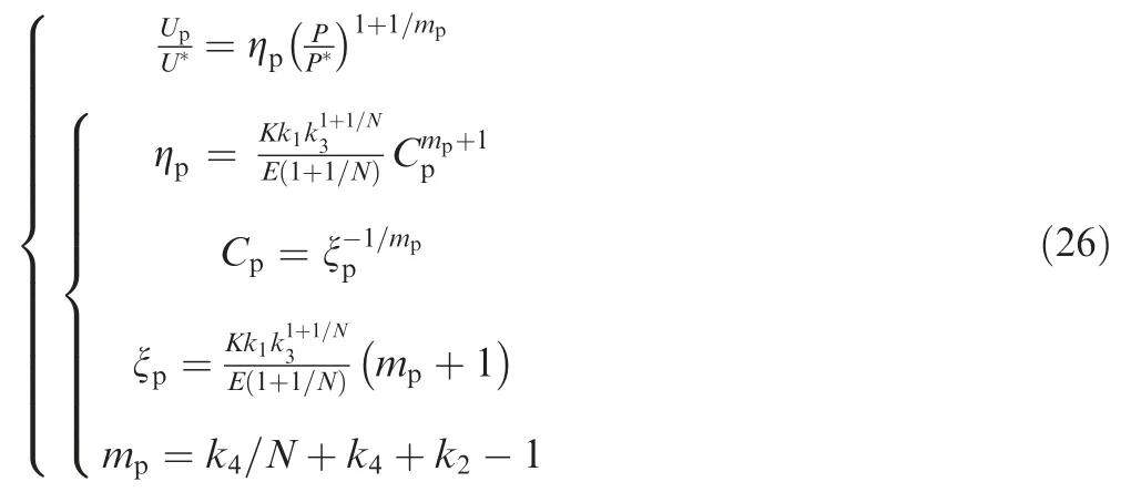
where ηis the curvature of purely plastic energy-load curve.Therefore,Eq.(26) was defined as the energy-load model for purely plastic ball indentation.
2.4.Displacement-load models for ball indentation based on proportional superposition
Chen and Caiintroduced the proportionality factors λand λto relateandtoby the proportional superposition of elasticity and plasticity:

Because λand λare related to/by a power law and λis related to the indentation depth/by a decreasing powerlaw trend at the onset of indentation,then we can assume that

where-are constants.Substituting Eqs.(18),(26),and(28)into Eq.(27) yields

Eq.(29) was defined as the energy model for elastoplastic ball indentation.
If the strain energyof the loaded structural element is known,then the complementary energyis

whereis the total displacement of the ball indenter.
Substituting Eq.(29) into Eq.(30) and differentiatingwith respect toyields

Ifis initially 0 andis 0,then

By integrating Eq.(32) to Eq.(31)
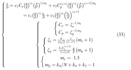
Eq.(33) was defined as the Proportional Superposition-based ElastoPlastic Model (PS-EPM) for displacement-load during ball indentation.
2.5.Ball indentation testing based on the PS-EPM
Rearranging Eqs.(1) and (3) yields the following expression for:
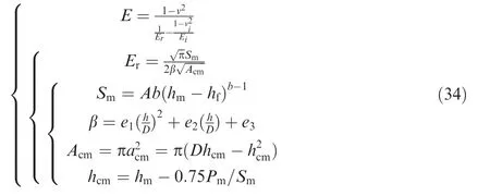
where the values of,,andare given in Table 1 of Ref.7.Rearranging Eqs.(17),(25),and (33) gives

Table 1 Parameter values of the purely plastic displacementload model for ball indentation.

Table 2 Parameter values of the PS-EPM.
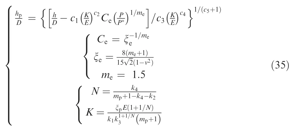
which is the inversion model for the material constantsand.If we obtain a {,}dataset from the indentation,we may then calculateby substituting,,,,andinto Eq.(35)and plotting the/*-/curve.
Fig.2 shows the procedure used to obtain theandparameters of the R-O relationships with Eq.(35) based on the experimental/*-/curve:
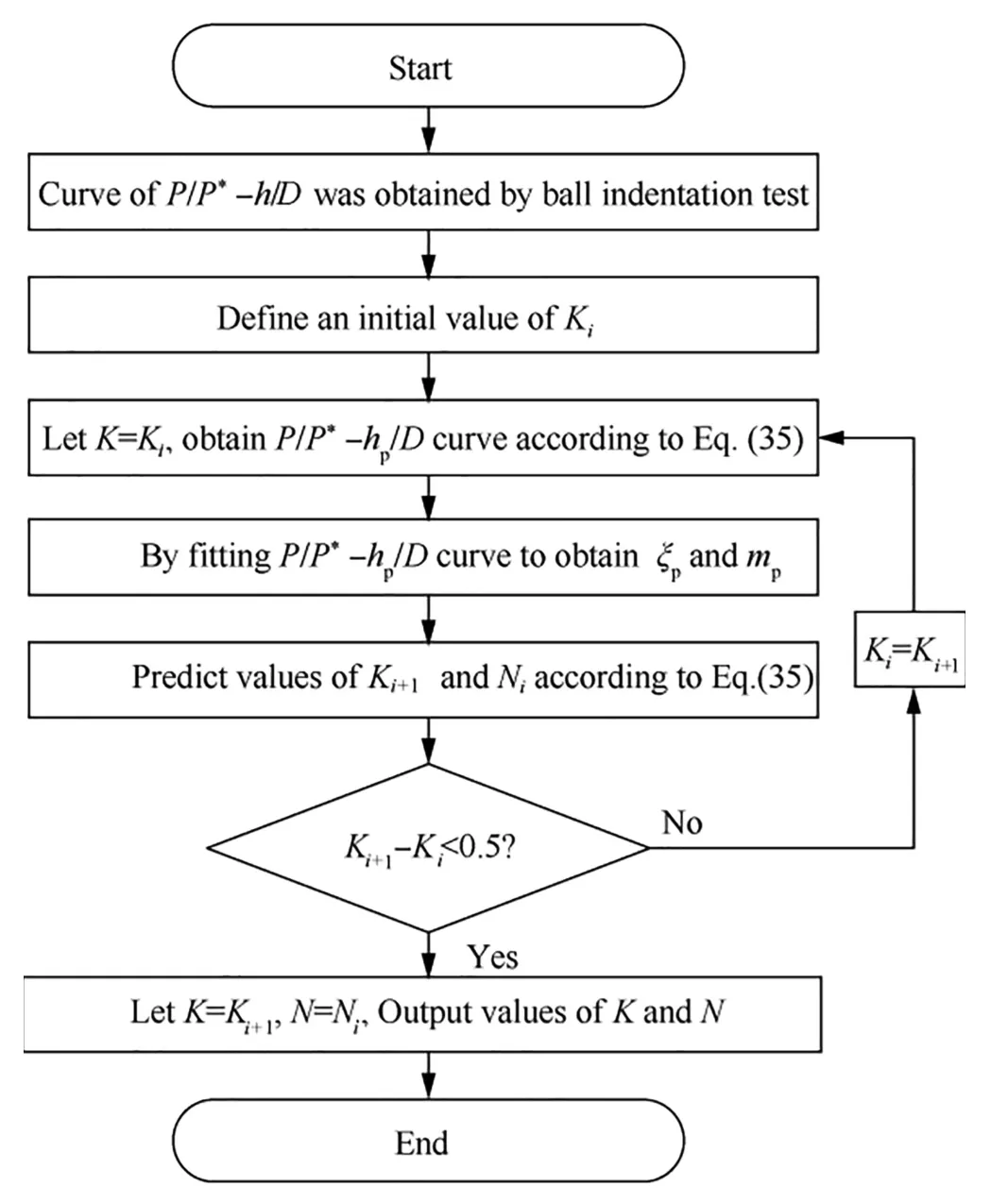
Fig.2 Flow chart for determining parameters of R-O law.
(1) Define an initial value ofto obtain the purely plastic/* -/curve.
(2) Take the experimental data corresponding to∈(0.015,0.035) and perform a regression between the purely plastic/* -/curve to obtain ξand.
(3) Predict the value ofby using,and then obtain a new predictedby using ξ,,and.
(4) Go back to step 1,and use the newas the initial value.Repeat steps 2 and 3 untilandhave converged.
(5) The convergedandvalues are the elastoplastic material parameters produced by inverse modeling of the experimental data.Theandvalues may then be used to calculate the tensile strength of the material:

whereis the natural logarithmic constant.Because,,andare known,the stress-strain relationships may then be obtained from the R-O relationships.Similarly,it is easy to obtain the yield strengthwith the methods of the ISO 12135 standard.
Above,the method to obtain the parameters of the R-O relationships (,,and) and strength (and) of a material by using the PS-EPM and experimental data from a single run of ball indentation was described.We call this Ball Indentation based on Elastoplastic Proportional Superposition(BI-EPS) method.
3.Methods for determining the parameters of the PS-EPM
The PS-EPM (Eq.(33)) is an analytical expression of the dimensionless displacement-load relation for ball indentation under elastoplastic conditions that is based on the equivalenceof energy density principle.In theory,the PS-EPM is conforming to dimensional analysis;it is a purely mathematical equation with wide applicability.If this model truly describes the universal mechanical laws that govern the ball indentation problem,then its parameters can be determined through a small number of FEAs based on a specified set of material constants(,,,and)and geometric parameters like the diameterof the indenter.Therefore,the PS-EPM is essentially a semi-analytical solution.
3.1.FEA model
The displacement of a ball indenter under elastoplastic conditions is given by the proportional superposition of the purely elastic displacementand the purely plastic displacement.To determine the parameters of the PS-EPM,andof the purely elastic model(Eq.(17))andtoof the purely plastic model (Eq.(25)) need to be determined.andcan be determined with the Hertz solution (see Section 2.2),whereastocan be determined in the FEA by specifying the material constants and geometric parameters.
FEA was conducted on the elastoplastic contact problem for ball indentation using ANSYS 14.5.Because the deformation caused by ball indentation is symmetric,a twodimensional axisymmetric mesh was used for the FEA model.Fig.3 shows the loading of the indenter in the model,the contact constraints of the ball indenter,the displacement constraints of theaxis (i.e.,axis of symmetry) in thedirection,and the displacement constraints of the far end in thedirection.PLANE182 plane elements were used to model the symmetric surfaces of the ball indenter and specimen.Because the contact zone between the ball indenter and specimen experienced the greatest stress,a high-density mesh was used to model this region.The dimensions of each grid at the contact zone were 0.05 mm × 0.05 mm for the indenter and 0.02 mm × 0.04 mm for the specimen.The grid dimensions gradually expanded away from the contact zone,and the largest grids were 25 times larger than those of the contact zone.The upper and lower contacting parts were modeled with TARGET169 target elements and CONTACT172 contacts elements.
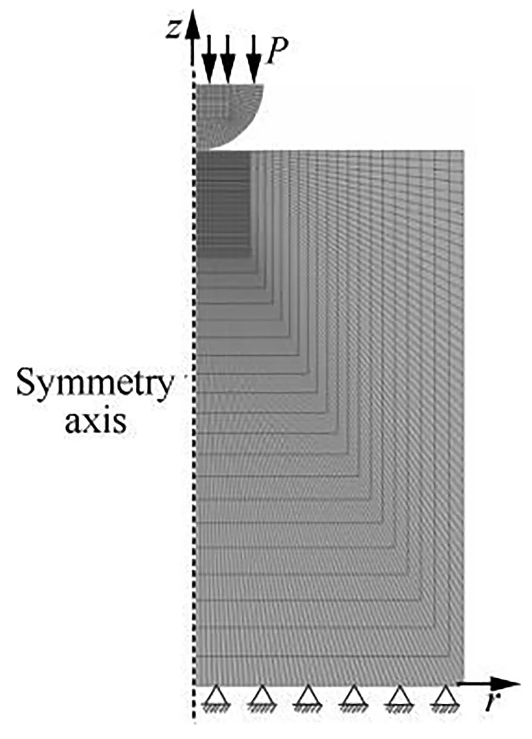
Fig.3 FEA model of ball indentation.
Ball indenters with diameters () of 1,1.5875,and 2.5 mm were selected for the simulation,andandwere set to constants of 600 GPa and 0.28,respectively (i.e.,tungsten carbide).The specimen material was set to steel with,,,andvalues of 200 GPa,0.33,500 MPa,and 10,respectively.The mesh model of the specimen was a cylinder with a diameter of 10 mm and height of 10 mm.The load-displacement dataset {,} was obtained through simulations with the FEA model of the indented specimen and was used to create dimensionless load-displacement FEA curves.Fig.4 shows the dimensionless load-displacement FEA curves of each indenter diameter.The curves are highly similar,which indicates that they are independent of the indenter diameter.Therefore,one ball indenter diameter (2.5 mm) was used in the subsequent numerical analyses and model validation.
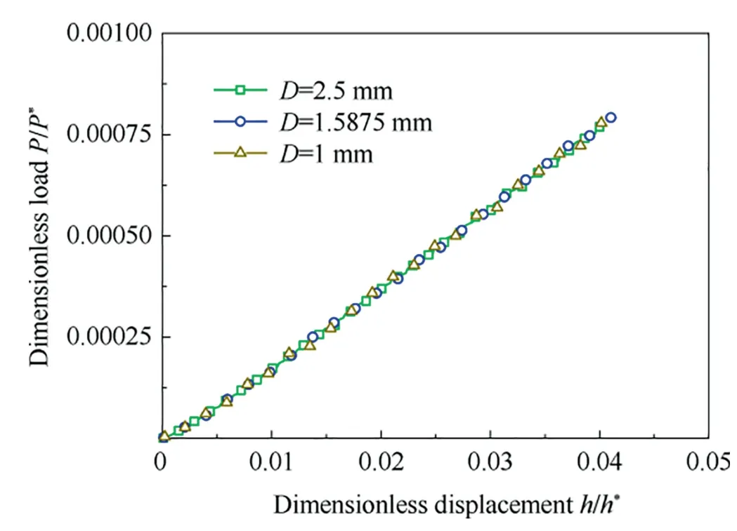
Fig.4 Dimensionless load-displacement curves with different ball indenter diameters.
3.2.Methods for parameter determination
This paper performed FEA simulations of ball indentation on five materials with a constant=500 MPa and variable(=2,3.33,5,7,and 10).The load-displacement dataset{,} was then obtained by FEA and converted into the dimensionless load-displacement curves,and the experimental data corresponding to these curves(/∈(0.015,0.035))were extracted,ξandwere then obtained for each material by fitting the dimensionless load-displacement curves to the experimental data according to the Eq.(24).
Rearranging Eq.(24) obtains

Five sets ofvalues can be obtained from the five sets of ξvalues.The first expression in Eq.(37)may be interpreted as an exponential function that relatesto 1+1/;we clarify this by showing a scatter plot ofversus(1+1/)in Fig.5.Therefore,andcan be obtained by fitting an exponential function to the plot ofversus (1+1/).The third expression in Eq.(37) may be interpreted as a linear function that relatesto 1/.Therefore,andmay be obtained from the gradient and intercept of the linear fit toversus 1/.The resultingparameters are listed in Table 1.
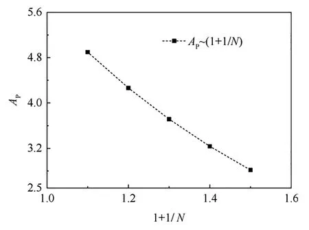
Fig.5 Ap versus (1+1/N) plot.
In addition toto,the PS-EPM also contains the unknown parametersto,which are obtained via FEA.For this FEA of ball indentation,was set to 70,100,150,and 200 GPa,andwas set to 300,500,800,and 1000 MPa;was set to 2.5,3.33,5,7,and 10.The load-displacement dataset {,} was then obtained by FEA and converted into the dimensionless load-displacement dataset {/*,/}.The PS-EPM (Eq.(33)) was then used to perform a regression analysis on the resulting dimensionless load-displacement curves and obtain the values ofto,as listed in Table 2.
4.Simulations with the FEA model for validation of the PSEPM
Hereinafter,the term ‘‘forward prediction” pertains to the numerical prediction of the load-displacement curve that corresponds to a known stress vs.strain relationships,and the term ‘‘reverse prediction” pertains to the numerical prediction of the stress-strain curve that corresponds to a known loaddisplacement relationships.
4.1.Forward prediction
Simulations of ball indentation were performed by using the R-O relationships as the conditional constitutive relation.The curves of/*-/were obtained from FEA,whereas the theoretically predicted curve for the dimensionless loaddisplacement relation was plotted by calculating the/value for each/* value with the PS-EPM (Eq.(33)).
The material constants were defined as follows:={70 GPa,200 GPa},={300 MPa,500 MPa,800 MPa,1000 MPa},and={2.5,3.33,5,7,10}.The theoretically predicted curves and FEA curves for/*-/are shown in Fig.6.The theoretically predicted curves and FEA curves agree well.Therefore,the PS-EPM is applicable to forward prediction of the ball indentation problem and has high accuracy.
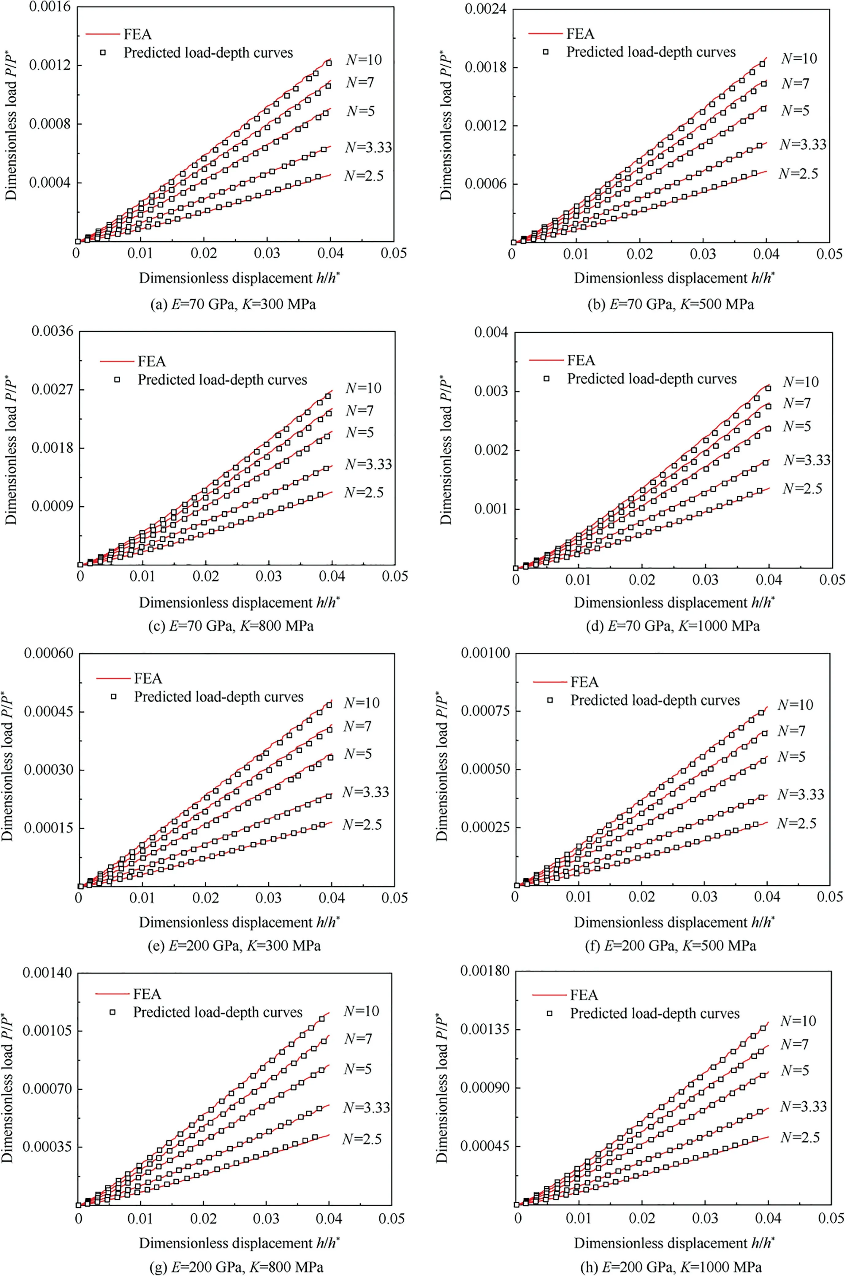
Fig.6 Comparison between the predicted load-displacement curves and FEA curves.
4.2.Reverse prediction
Simulations of ball indentation were performed by using the R-O relationships as the conditional constitutive relation.The material constants,,andwere predicted with the BI-EPS method by performing FEA to obtain the{,}dataset,then the predicted stress vs.strain curves of R-O relationships were obtained.
The material constants were defined as follows:={70 GPa,200 GPa},={300 MPa,500 MPa,800 MPa,1000 MPa},and={2.5,3.33,5,7,10}.The curves predicted with BI-EPS and derived from the FEA using the conditional R-O relationships are shown in Fig.7 and agreed well.Therefore,ball indentation based on PS-EPM is applicable to reverse prediction of the ball indentation problem and has high accuracy.
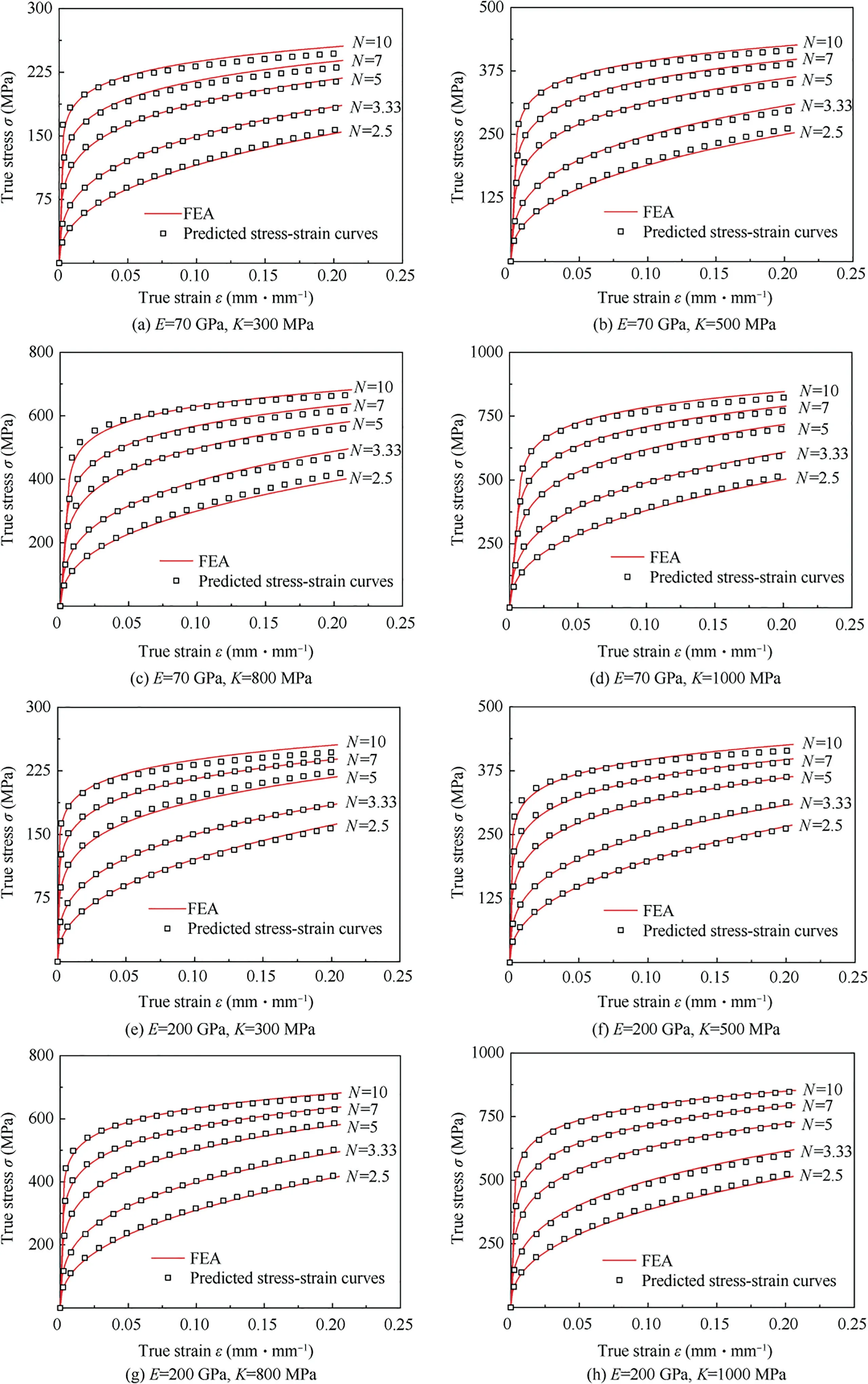
Fig.7 Comparison between the predicted stress-strain curves and FEA curves.
5.Application of the BI-EPS testing method
Five material parameters can be obtained with the BI-EPS testing method:the constants,,andfrom the R-O relationships and the constantsandfor the material strength.We validated the effectiveness of the BI-EPS method by comparing its results to the material constants obtained from uniaxial tensile tests.
5.1.Materials,testing devices,and experimental procedures
Ball indentation was performed on five types of aluminum alloy and six types of steel.Table 3 presents the general material designation,parameters of the R-O relationships (,,and),and material strength (and).Poisson’s ratios of the aluminum alloys and steels were 0.3 and 0.33,respectively.

Table 3 Mechanical properties and plasticity parameters from the R-O relationships.
An indentation instrument produced by Chengdu Miniature Mechanical Testing Science &Technology Co.Ltd.was used as the testing device;Fig.8 shows a photograph and schematic of this device.The load and displacement sensors of the instrument have maximum limits of 1200 N and 2 mm,respectively,with a precision of 0.5%.
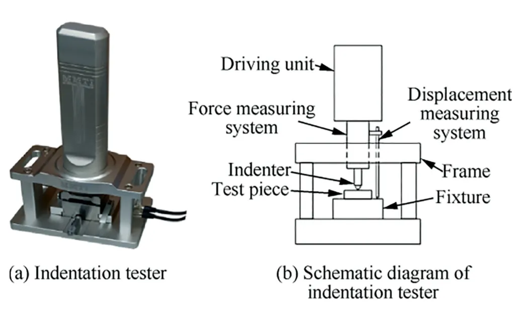
Fig.8 Testing devices.
The ball indenter was made of tungsten carbide,and it had a Young’s modulus of 600 GPa and Poisson’s ratio of 0.28.The surface roughness of the ball indenter was no more than 0.2 μm.A 1 mm indenter was used to test the P92,30Cr,and SA302B materials,and a 1.5875 mm indenter was used with the 5083-H116,5052-H24,16MnR,16Mn,A508-III,and 7075-T6511 materials.The 6061-T6511 and 6082-T6 materials were tested with a 2.5 mm indenter.The aluminum alloy specimens were cylinders with a height of 10 mm and diameter of 25 mm.The steel specimens were rectangular with a height of 10 mm and testing surface dimensions of 20 mm × 20 mm.The specimen ends had a parallelism of less than 0.02 mm/50 mm,and they were polished to a surface roughness of<0.8 μm.
During the indentation test,the loading and unloading were both controlled by the displacement alone.The loading rate was 3 μm/s,and the unloading rate was 1 μm/s.The load and displacement signals were sampled at a rate of 20 Hz.
Three indentation tests were performed on each indentation surface,and the indentation points had gaps of 2 mm.To avoid the errors associated with the first indentation,thecurves of the second and third indentation points were used to represent the effectivecurve.Most of thecurves had a maximum indentation depth () to indenter diameter () ratio greater than 0.04.
5.2.Comparison between experimental and theoretical results
As shown in Fig.9,22 effectivecurves were obtained from specimens corresponding to the 11 different types of materials.The BI-EPS method was used to obtain the parameters of the R-O relationships (,,and) from thesecurves and thus predict the σε curves.Fig.10 shows the predicted σε curves of the 11 materials and their counterparts from uniaxial tensile testing;the curves show good agreement.Table 4 presents the parameters of the R-O relationships that were predicted from indentation tests and the goodness-of-fit of each predicted σε curve.The relative error between the predicted and experimentalvalues was usually less than 2% and less than 5% in a few instances.All of the predicted σε curves had high goodness-of-fit scores,and all materials except one (95%)had scores higher than 96%.Therefore,the σε curves obtained by the BI-EPS method agreed well with those from uniaxial tensile testing.
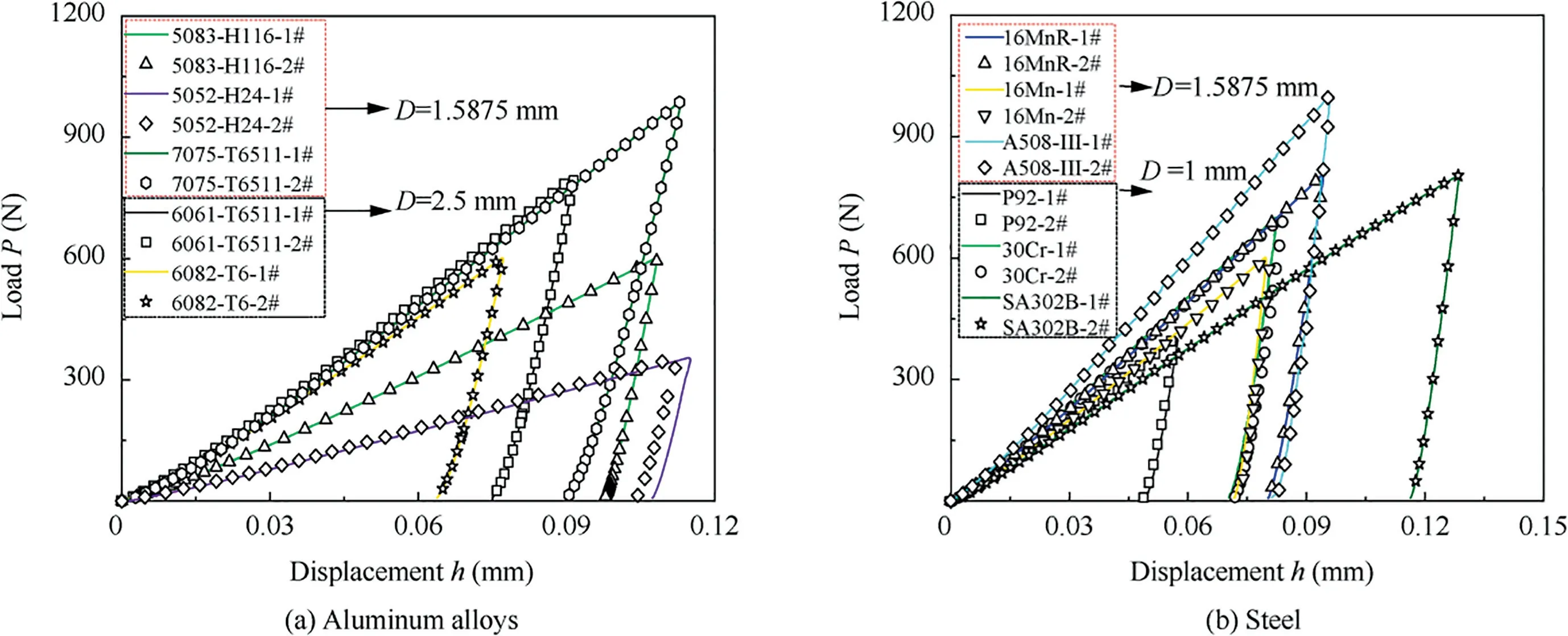
Fig.9 Load-displacement curves from ball indentation.
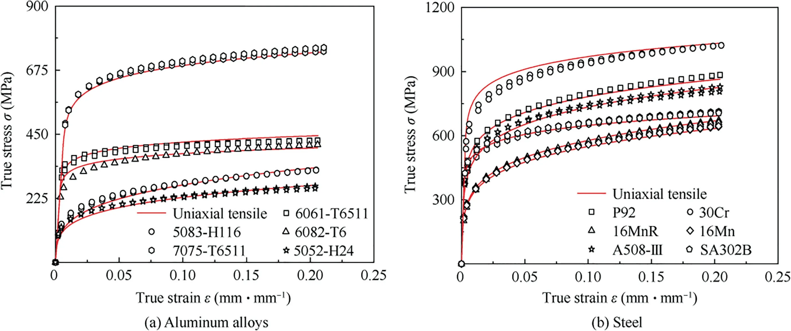
Fig.10 Comparison of curves predicted from the R-O relationships and curves from uniaxial tensile tests.
Table 5 compares the material strengths (and) that were obtained by the BI-EPS method and uniaxial tensile tests for the 11 materials.The relative errors between the predicted tensile strengths () and results of the uniaxial tensile tests were generally less than 4% for all materials.The relative errors between the predicted yield strengths()and results of the uniaxial tensile tests were generally less than 15%.

Table 4 Goodness-of-fit of the parameters from the R-O relationships and σ-ε curves.

Table 5 Comparison of the yield and tensile strengths obtained by the BI-EPS method and uniaxial tensile testing.
6.Conclusions
This paper makes the following contributions to the literature:
(1) Based on the equivalence of energy density principle,semi-analytical models were proposed for the displacement-load relations of purely linear elastic ball indentation (Eq.(17)) and purely plastic power-law ball indentation (Eq.(25)).
(2) The semi-analytical PS-EPM (Eq.(33)),which incorporates the proportionality factors λand λ,was proposed to model the proportional superposition of purely linear elastic energy and purely power-law plastic energy.The BI-EPS testing method based on the PS-EPM was proposed for obtaining the constitutive relations of powerlaw materials.
(3) The parameters of the PS-EPM may be obtained by performing a small number of FEAs.The theoreticalcurve from the PS-EPM closely agreed with the FEA results,and the theoretical stress vs.strain curve provided by the BI-EPS testing method also closely agreed with the FEA results.
(4) Ball indentation were performed on 11 metallic materials,and the stress vs.strain curves,Young’s modulus,and tensile strengths obtained with the BI-EPS testing method agreed well with the results of conventional uniaxial tensile tests.
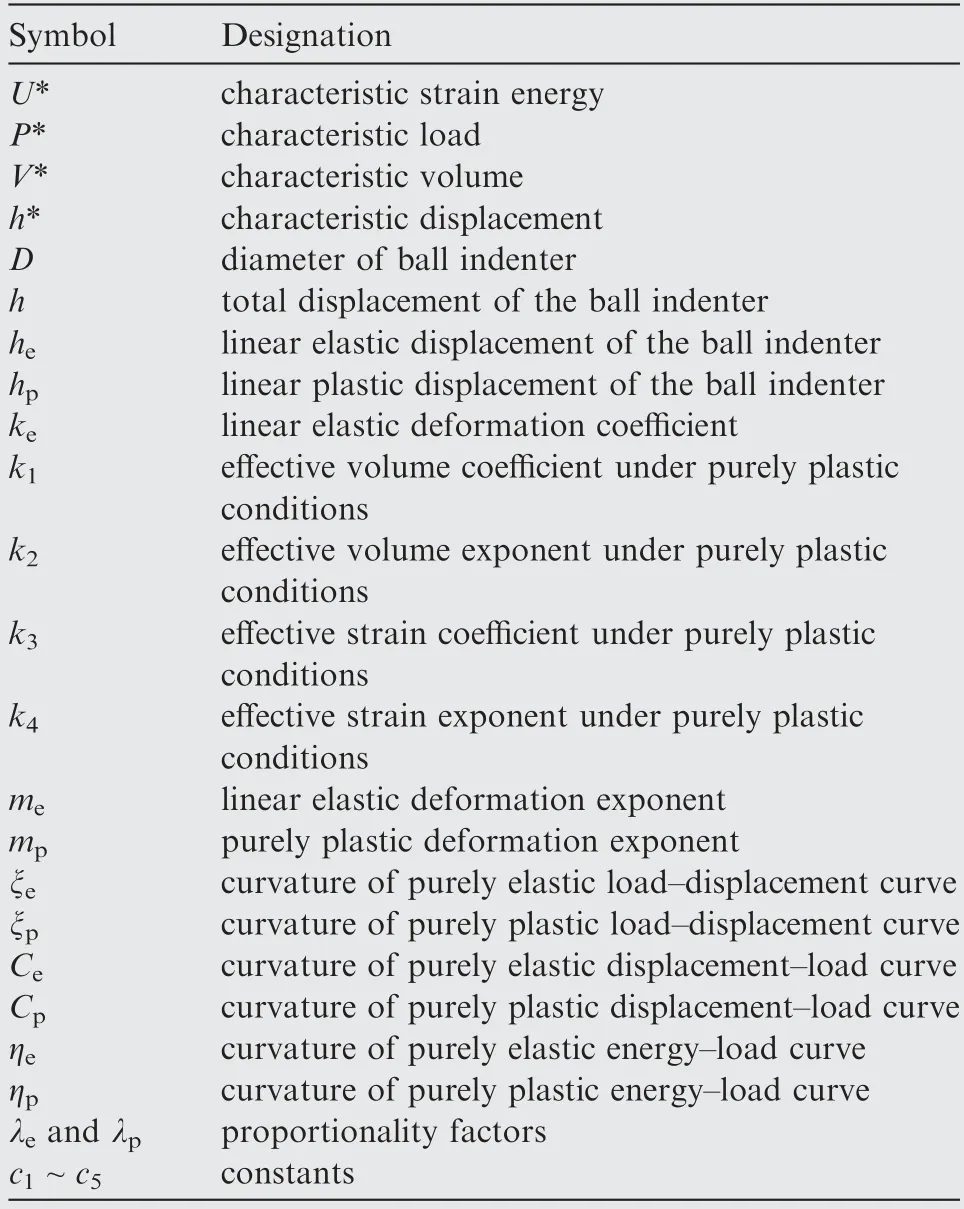
7.Symbol and designation
The authors declare that they have no known competing financial interests or personal relationships that could have appeared to influence the work reported in this paper.
This study was co-supported by the National Natural Science Foundation of China (Nos.11872320 and 12072294).
 Chinese Journal of Aeronautics2022年2期
- Chinese Journal of Aeronautics的其它文章
- Pressure-induced instability and its coupled aeroelasticity of inflated pillow
- Adjoint boundary sensitivity method to assess the effect of nonuniform boundary conditions
- Transit time difference and equal or non-equal transit time theory for airfoils with lift
- A boundary surrogate model for micro/nano grooved surface structure applied in turbulence flow control over airfoil
- Nonlinear uncertainty quantification of the impact of geometric variability on compressor performance using an adjoint method
- High precision and efficiency robotic milling of complex parts:Challenges,approaches and trends
