Passage shock wave/boundary layer interaction control for transonic compressors using bumps
Yongzhen LIU ,Wei ZHAO,c ,Qingjun ZHAO,c,* ,Qiang ZHOU ,Jianzhong XU,c
a Institute of Engineering Thermophysics,Chinese Academy of Sciences,Beijing 100190,China
b School of Aeronautics and Astronautics,University of Chinese Academy of Sciences,Beijing 100049,China
c Innovation Academy for Light-duty Gas Turbine,Chinese Academy of Sciences,Beijing 100190,China
KEYWORDS Flow separation;Passage shock;Shock Control Bump (SCB);Shock wave/boundary layer interaction;Transonic compressors
Abstract Flow separation due to shock wave/boundary layer interaction is dominated in blade passage with supersonic relative incoming flow,which always accompanies aerodynamic performance penalties.A loss reduction method for smearing the passage shock foot via Shock Control Bump(SCB)located on transonic compressor rotor blade suction side is implemented to shrink the region of boundary layer separation.The curved windward section of SCB with constant adverse pressure gradient is constructed ahead of passage shock-impingement point at design rotor speed of Rotor 37 to get the improved model.Numerical investigations on both two models have been conducted employing Reynolds-Averaged Navier-Stokes (RANS) method to reveal flow physics of SCB.Comparisons and analyses on simulation results have also been carried out,showing that passage shock foot of baseline is replaced with a family of compression waves and a weaker shock foot for moderate adverse pressure gradient as well as suppression of boundary layer separations and secondary flow of low-momentum fluid within boundary layer.It is found that adiabatic efficiency and total pressure ratio of improved blade exceeds those of baseline at 95%-100% design rotor speed,and then slightly worsens with decrease of rotatory speed till both equal below 60%rated speed.The investigated conclusion implies a potential promise for future practical applications of SCB in both transonic and supersonic compressors.
1.Introduction
The potential of more mechanical energy transferred efficiently from transonic compressors to air flows has being pursued for several decades via multiple approaches,and the work done per stage of the compressor relates with the fluid deflection and the tangential Mach number.One path for increase the stage compress ratio is to enhance the deflection angle of airflow,while the excessive flow turning in the blade rows is limited by boundary layer separation.An alternate approach marches with persistent promotion of revolving speed to increase the tangential Mach number.This is implying that a successive increase in the rotational speed of transonic compressors leads to a considerable rise in the inflow velocity relative to the compressor blades from subsonic or transonic to supersonic region.However,higher strength shock waves have being incurred in the blade passages with the raise of blade spinning speed,meaning more losses from shock waves and their interactions with boundary layers (Shock Wave/Boundary Layer Interaction,SWBLI) except blade buffets induced by shocks.The loss caused by shock waves is relatively small,and still increase with the rising of relative inlet Mach numbers.However,the loss of boundary layer separation induced by shock wave accounts for a large proportion of the total pressure loss,even amount to 30%.Thus,it is necessary to diminish the boundary layer separation loss induced by shock while using the stronger shock to rise stage pressure ratio in highly loaded transonic compressors.
Over the years,various flow separation suppression techniques of SWBLI hitherto developed include active control(boundary layer suction,jet ejection and magnetohydrodynamic control and so on),passive control (vortex generators,cavity et al.) and hybrid control.Among the shockinduced separation loss reduction techniques,Shock Control Bump (SCB) are a relatively new class of flow control device that can provide several potential gains at transonic or supersonic external flow conditions in which shock waves usually exist.In addition,the shock-induced boundary layer separation is mainly the interaction between shock foot and boundary layer.The SCB,global gains from local effects,have the benefit that relatively small modifications are introduced to the baseline geometry can achieve the desired effect.
The SCB were first emerged on transonic airfoils to mitigate problems caused by high-shock strength and maximize the drag-divergence Mach number during the late 1970s.According to the application and evolution of SCB,they can be regarded as three type of groups.The first group has been mainly focused on transonic and supercritical aerofoils of wings since the 1970 s,which can significantly decrease boundary layer separation loss and wave drag.The flow physics,which is considered as smearing effect of SCB on configuration of the near-normal shock wave on the wing surface,have being acknowledged comprehensively that an original single shock can be split into series of weaker(oblique)shocks or compression waves to decelerate flow velocity more gradually for lowering stagnation pressure loss and wave drag.Meanwhile,some optimization techniques and parameterization methods were employed to better define SCB profile for improving the efficiency of SCB.The second group has been concentrated on supersonic/hypersonic mixed intake since about 2005,within which the last single normal shock can be transitioned to a λ-shock structure with local flow deflection via three-dimension (3D) SCB structure for more benefits than 2D bump.Furthermore,a deformable 2D bump(active measure to some extent) has been also introduced to suppress the cowl shock-induced separation in hypersonic inlets for more adaptabilities to various Mach numbers,indicating that coupling of the precompression effect and the acceleration effect of the bump significantly shrink the shock-induced separation region.The last group aims at transonic compressor blade passages in turbomachinery since about 2015,through which its relative Mach number attained higher than 1.3 can incurs a family of passage shock waves as well as SWBLI,and the flow become more complicated due to the radial transportation of fluids in boundary layer under centrifugal force.The essence of flow loss reduction by SCB can be placed on the supersonic flow with lower Mach numbers ahead of the shock foot via precompression effect to delay the shock-induced separation.
The distinctions among the three groups of investigations lie in flow conditions,flow field structure with shock configurations and their interactions with boundary layer.Compared to the first group which is of classic external flow characteristics,the velocities occurred in the second and the third groups are much higher.Their flow fields usually consist of multiple oblique shock waves and a single last normal shock,and their flow through specific passages are of constrained and forced features.In addition,the third group of investigations confront more complex situations than the other two ones.The airflow through revolving blade passages is a kind of confined and forced periodic flow with low supersonic Mach number in a relative cylinder reference frame,appearing the complex three-dimensional flow characteristics of the SWBLI.Actually,fewer investigations on its application in turbomachinery have been publicly published till now and scarcely focuses on flow physics of SCB in transonic compressor.
In order to promote the aerodynamic performance of transonic compressors,a detailed design method of SCB profile with constant adverse pressure gradient on the windward section is introduced to suppress the boundary layer separation induced by passage shock foot with Rotor 37,and validated via numerical results from RANS method.In addition,the flow physics of SCB operating on blade suction surface have been investigated in detail by analyzing the aerodynamic performance and flow field characteristics between baseline and improved rotor at both on-design and off-design conditions.
2.Investigated compressor rotor
2.1.Baseline rotor model
NASA Rotor 37 is taken as baseline model for investigation of SCB on rotor blades.Its aerodynamic performances both from numerical simulations and experimental tests conducted by NASA Lewis Research Center in the late 1970shave been published in details in NASA technical reports and North Atlantic Treaty Organization Advisory Group for Aerospace and Development (NATO AGARD) literatures.The initial and boundary conditions of Rotor 37 are consistent with the experimental data for investigation of numerical simulations,and its experimental results have also been taken as validation data for numerical method.Main aerodynamic and structure parameters list as following in Table 1.

Table 1 Key design parameters of Rotor 37.

Table 2 Detailed parameters for ramp profile of SCB s at different spans.
The rotor design pressure ratio is 2.106 at a massflow of 20.19 kg/s.The rotor aspect ratio is 1.19 and the hub/tip radius ratio is 0.70.The rotor tip clearance at design speed is 0.356 mm,corresponding to 0.5% of inlet span and 0.7% of exit span.The inlet relative Mach number is 1.13 at the hub and 1.48 at the tip at the design tip speed of 454 m/s.Since the inlet relative velocity of the rotor from the hub to tip is supersonic,a three-dimensional shock wave surface structureis formed in the blade passage,and the passage shock impingement position on the blade suction surface is about 50%of the chord length of the blade.In addition,there is a strong shock boundary layer interaction on the blade suction surface above 50% spans,which results in the decrease of aerodynamic performance of the rotor.
2.2.Structure of SCB for modification
In order to eliminate aerodynamic loss stemmed from shock waves and SWBLI,a kind of SCB with plateau profile has been employed for improvement of global aerodynamic performances.It is found that initial position of SCB structure is crucial to suppress loss of stagnation pressure in blade passages.The structure of SCB,shown as Fig.1,is composed of ramp,crest plateau and tail sections,indicated with,andfor corresponding section length respectively.SCB is merged with baseline profile of suction side and its three sections connect smoothly as a curve with third-order continuity by means of forth-order spline fitting,which global length and height are labeled asandrespectively.Ramp profile of SCB designed is expected to deaccelerate supersonic inflow velocity with series of compression waves both for higher inflow recovery coefficient and less loss of SWBLI.In addition,the height of SCB is designed lower than the displacement thickness of local boundary layer with little drag penalty in blade passage.
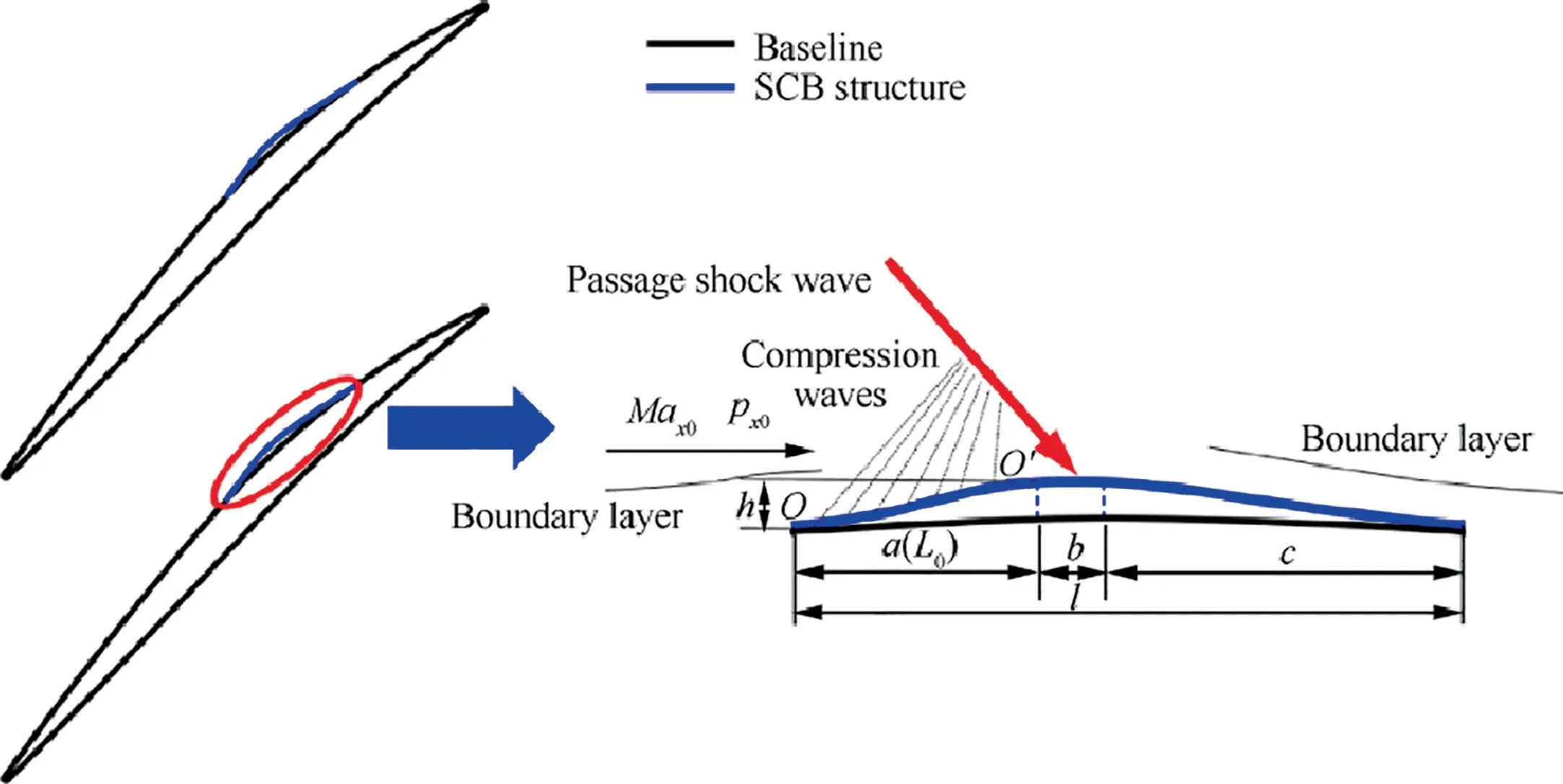
Fig.1 Geometry of SCB.
Since the momentum of low-energy fluid in boundary layer could not remain its form under adverse pressure gradientand there may exist stronger adverse pressure gradient in highloading supersonic blade passage,separations possibly occur due to high strength of shock waves and consequent SWBLI.Hence a moderate adverse pressure gradient and delaying of flow separation in boundary layer both are hoped in construction of SCB.The initial position of SCB is related to the upstream influence length(the distance separating the interaction onset from the shock foot in the inviscid-flow model)of SWBLI and location of shock impingement point.The upstream influence length scales with the incoming boundary layer thickness or its displacement thickness (related to the upstream Mach number).According to other researchers’experienceand numerical simulation results,shock-induced boundary layer separation was effectively suppressed when the shock wave was located at the crest plateau section of the SCB.Therefore,the initial position of SCB can be determined by the shock wave position and the upstream influence length.Furthermore,the geometric parameters of SCB are additionally correlated to Mach number Ma,static pressure p,wall turn angle θat initial pointand the position of terminal point.The effect of viscosity here is considered with an empirical equation correction finally..
The ramp profile of SCB with constant adverse pressure gradient is depicted in Fig.2,and the curve function can be determined by the governing equations as follows:
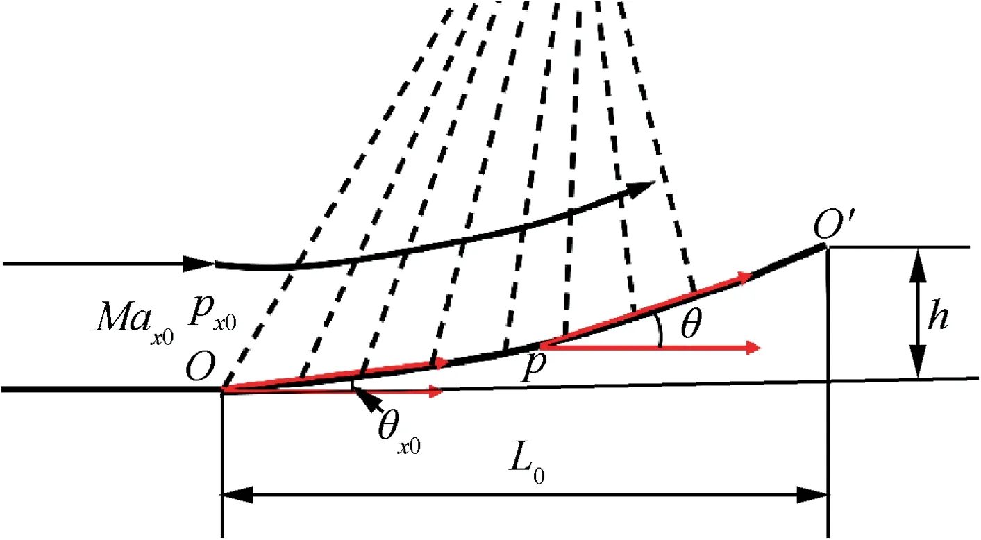
Fig.2 Concave curved compression surface with constant adverse pressure gradient.
Without considering viscous effect,assume that the static pressure distribution on the ramp of the SCB is Eq.(1).

where the parameteris the adverse pressure gradient;is streamwise coordinate;is streamwise position where the wall pressure begins to rise induced by shock.The pressurealong Mach lines at various wall position is given by Eq.(2),and the Mach number distributions on the ramp with constant adverse pressure gradient can be obtained by Eq.(3).
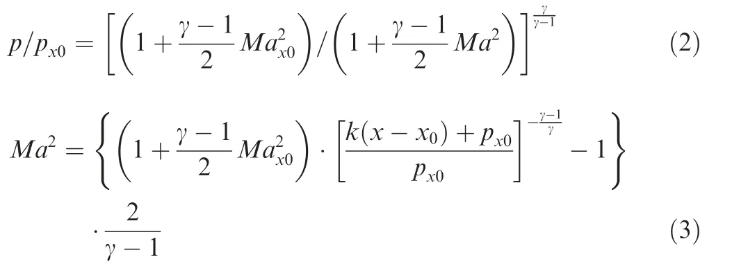
where γ is ratio of specific heats.
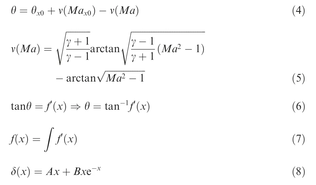
Relationship of Mach number with wall turn angle on ramp of SCB can be derived from simple wave theory and Prandtl-Meyer function,Eq.(4) and Eq.(5).Thus,combining slope of profile with turn angle,the ramp profile with negative curvature,expected to generate constant adverse pressure gradient,can be obtained from Eq.(6) and Eq.(7).Consequently,the acquired ramp profile is corrected by Eq.(8),with the order of half the boundary layer displacement thickness at point,which is reported applying in air intake and agreed well with the experimental results.The parametersandof Eq.(8) are boundary layer displacement thickness coefficients.In addition,since the flow velocity behind passage shock is subsonic,according to Ref.18,the crest plateau and tail sections of the SCB are designed linearly,and three sections of SCB are connected smoothly with fourth-order spline curves.
Iteration calculation process for ramp profile of SCB with constant adverse pressure gradient is illustrated in Fig.3,among which quantityis the objective to be computed iteratively and its initial value of quantityis set with 1.Finally,the profile equation for the ramp of SCB is derived through integration.Since the pointbelong to tail of ramp section,the quantityis calculated.Iterative calculation ceases till thedeviation betweenandis less than 10,and then quantityis output.10 control points have consequently been selected from pointto pointaccording to attained quantity.Then coordinates of the control points and ramp profile of SCB are acquired with Eqs.(1) to (8).
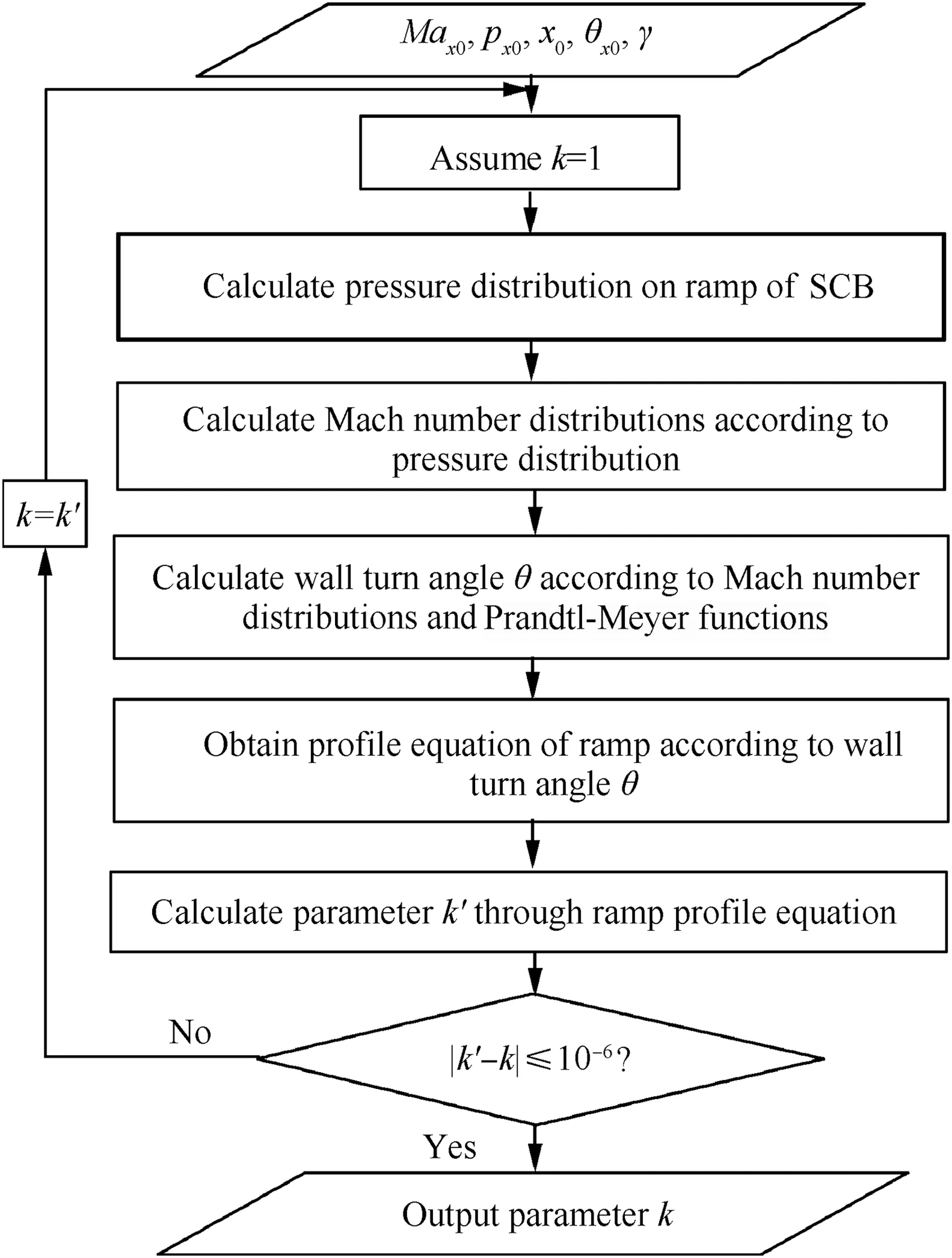
Fig.3 Calculation process of ramp curve.
For improved transonic compressor rotor,SCB structure herein locates impingement point of passage shock on blade suction side.In order to determine blade geometry with SCB,six blade profiles are chosen along blade spanwise,namely 0%,20%,40%,60%,80% and 100% spans.According to other researchers’experienceand numerical simulation results,the total length of SCB is 20% of section profile chord of each span herein.The length of ramp is upstream influence lengthwhile operating under design operating condition,and the upstream influence length of six spans are 3.1%,3.5%,6.1%,7.2%,7.9%and 6.2%of each corresponding chord respectively.The length of crest plateau zone is about 10% of SCB length,and the maximum height of SCB’s crest plateau zone is 0.35 of boundary layer thickness at initial point.From root to tip of the blade,detailed design parameters for the ramp profile of SCB with constant adverse pressure gradient are summarized in Table 2.Since SCB is located near the passage shock-impingement point on blade suction side,after completing six blade profiles with SCB,geometry of the improved blade is stacked smoothly along B-spline curves of each airfoil centroid.The distinctions in airfoil between baseline and improved profiles at 20%,60% and 100%of blade span are depicted as Fig.4,where parameteris the chord length of each blade span,and those in geometry between baseline and improved blade are also displayed as Fig.5.

Fig.4 Geometry of baseline and improved blade profiles at 20% span,60% span and 100% span.
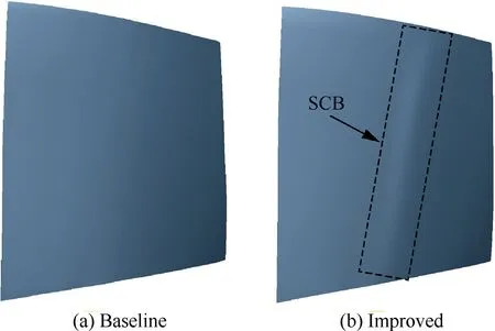
Fig.5 Geometry of two rotor blades.
3.Numerical simulation and validation
A commercial computational fluid dynamics software,ANSYS CFX 14.0,has been employed in this 3D viscous simulation investigations,which adopts the Reynolds-Averaged Navier-Stokes(RANS)method with finite volume integration,coupled implicit algorithm.The solver of CFX has been demonstrated capable to accurately predict the overall performance of the transonic compressor rotor,and it is well recognized that the deviation between numerical results and experimental data meets calculation accuracy of most cases involving compressors.Furthermore,the further evaluation of flow field using this code for transonic compressor rotor was performed by Refs..Flow fields predicted with CFX have been proved coinciding well with experimental data while involving shock-induced boundary layer separation and shock reflections within blade passage.
Meshes for 3D viscous computation are generated with a commercial software,Autogrid 5.In order to acquire higher quality of grids,the mesh of blade passage is split into several blocks,inlet block,blade-skin block,outlet block,inner block and butter-fly block with HOH meshes topology type.The topology and mesh of calculation domain are shown in Fig.6,and the matching periodic connected of mesh is adopted in the tip clearance by butterfly topology.Since mesh scale of boundary layer is crucial for numerical calculation accuracy and the predicted flow field,the distance of first layer mesh from blade surface is in the order of 1×10m to satisfy first cell<1.The Reynolds number in relative frame is in the level of 1×10with inlet relative velocity and chord length of medium blade,and hence fully turbulent state can be assumed in the boundary layer.The hub,shroud,and blade surface are set as no-slip and adiabatic wall boundary conditions.Besides that,rotational periodicity is used for the circumferential sides.The overall performance curve of the rotor is obtained by adjusting the outlet pressure.The distribution profiles of total temperature,total pressure and flow angle at inlet are taken from Rotor 37 experimental condtions.

Fig.6 Topology and mesh of calculation domain.
The validation of numerical simulation is key to evaluate reliability and feasibility of numerical method.Validation of grid independence has been conducted via variations of global grid node number in computational domain.Keeping height of the first layer mesh from blade surface 1 × 10m,validation results of global node quantities are depicted as Fig.7.It is found that both the adiabatic efficiency and total pressure ratio at peak efficiency point gradually increase with grid node number.When the number of grids in the calculation domain reaches 2.3 million,the numerical simulation results are basically unchanged with the increase of the number of grids.As for 2.3 and 2.6 million nodes,difference of adiabatic efficiency and total pressure ratio are 0.03% and 0.05% respectively,both less than 0.1%.It is concluded that 2.3 million grid nodes are adequate for prediction of global Rotor 37 performance.
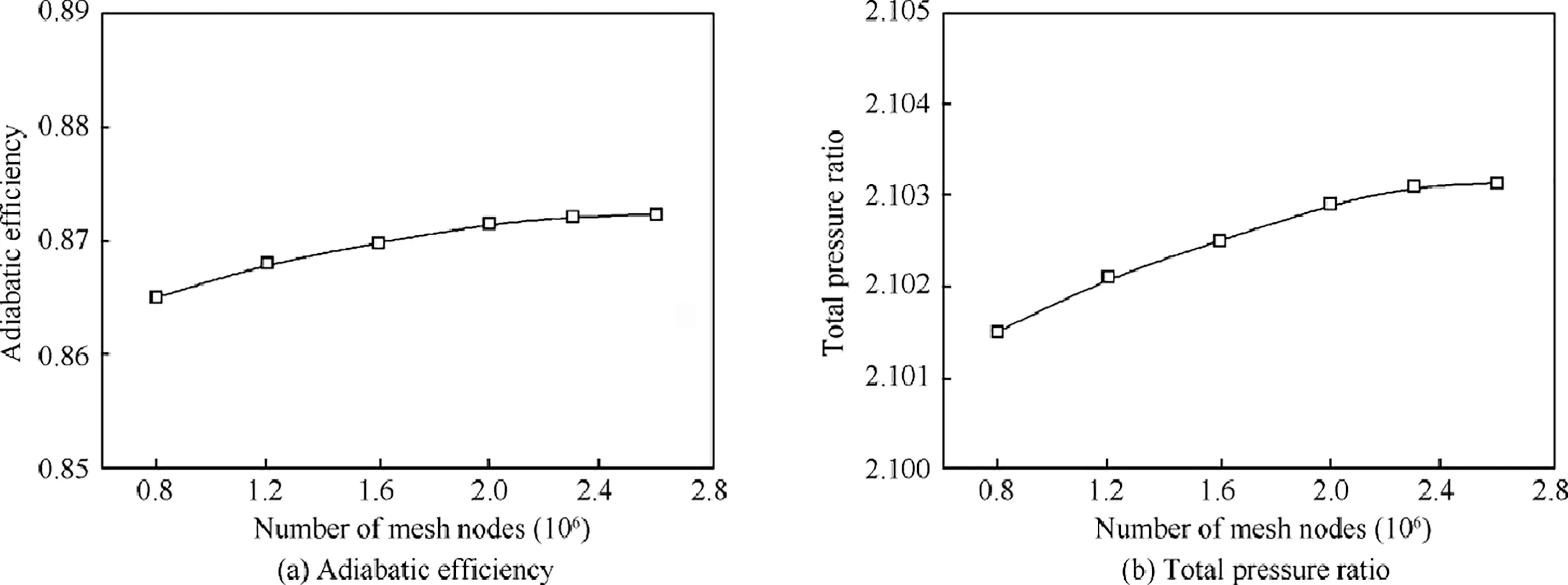
Fig.7 Variation of aerodynamic performance at peak efficiency point with different mesh nodes.
Certification of turbulent model has been carried out in a similar way with several candidates involving-ε,-ω and Shear Stress Transport(SST)-ω,which is composed of comparisons on overall performances and detailed flow field characteristics for Rotor 37.Comparison on adiabatic efficiencies and total pressure ratios at various mass flows is shown as Fig.8.It is found that result predicted with-ε model agrees best with experimental data among three models,and maximum deviations of total pressure ratio and adiabatic efficiency appear less than 2% and 3% respectively.Spanwise distributions of total pressure ratio and total temperature ratio by three turbulence models at peak efficiency point are depicted in Fig.9,which shows that distribution curve with-ε model matches well with experimental data,indicating most feasible in numerical investigations.Analyses on relative Mach number contours at 50%and 95%spans predicted with-ε model have been executed as shown by Fig.10.It should be noted that both the predicted Mach number distributions and experimental data match rather well each other,implying the potential capabilities in further numerical simulations.
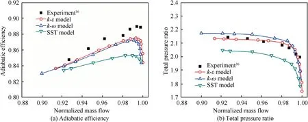
Fig.8 Comparison of numerical and experimental overall performance using different turbulence models.
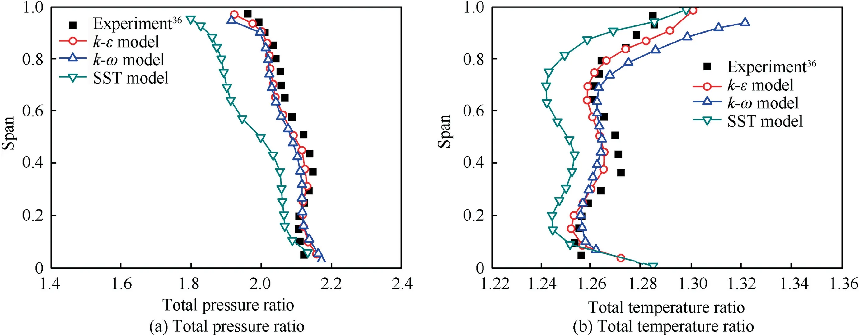
Fig.9 Comparison of key parameters using different turbulence models at design condition.
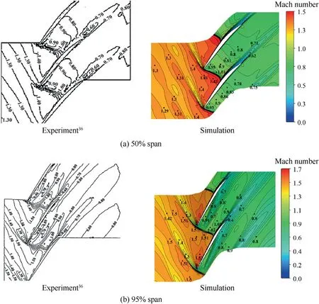
Fig.10 Comparison of relative Mach number contours at peak efficiency condition.
4.Results and discussion
4.1.Effects of SCB on overall performance
Analyses on overall performance of the baseline and improved model have been implemented based on comparison at design rotor speed,as schematically in Fig.11.Adiabatic efficiency and total pressure ratio of the improved model have been promoted 1.28%and 2.1%respectively compared with baseline at peak efficiency point.Both of them still have 0.67%and 1.02%increments near stall point.Contrast of aerodynamic parameters distributions in radial direction for both models have been applied as well.Spanwise distributions of overall performance for two models at outlets of rotor are graphically represented in Fig.12.It is found that adiabatic efficiency of improved model appears slightly lower than baseline blade at 40%spans below while modified blade exceeds the baseline at 40%-90%of blade spans with maximum value at about 60% span.It is also discovered that total pressure ratio of improved model surpasses baseline blade all over blade height,especially near at 60% blade span.Hence,it is clear that the structure of SCB displays capability for suppression of flow separation and promotion of stage loading.
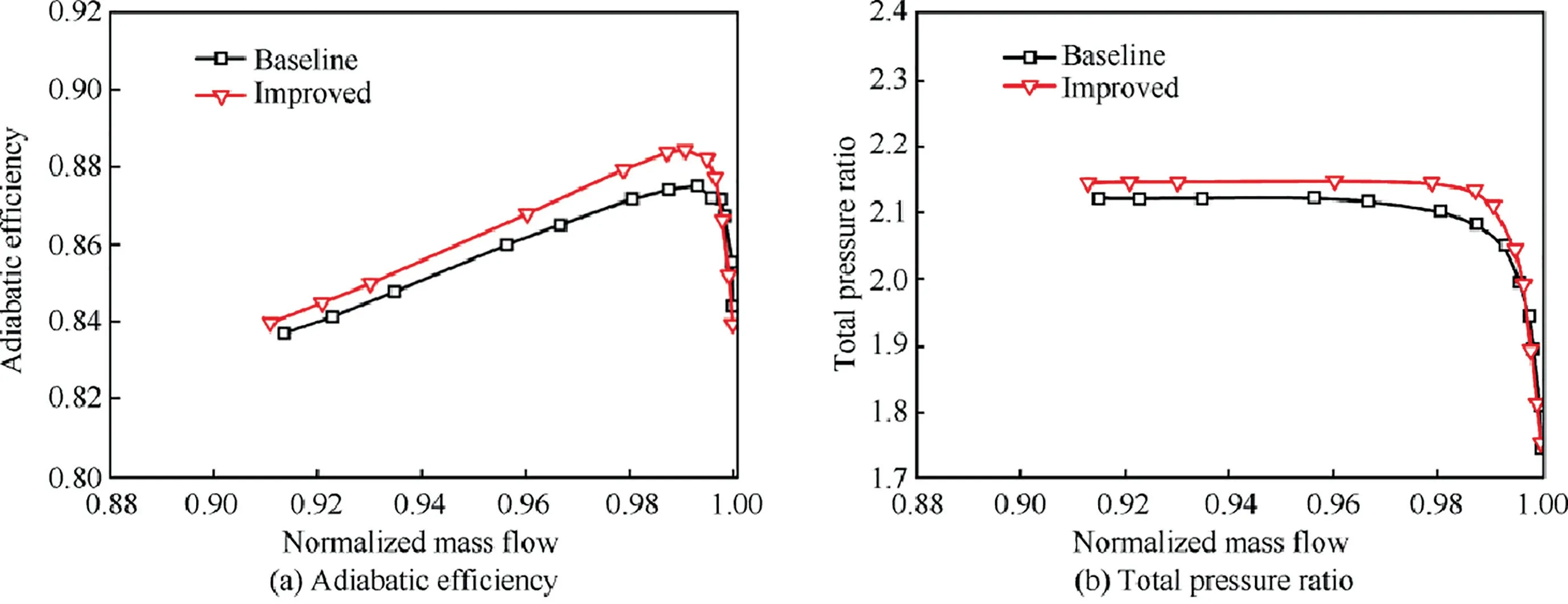
Fig.11 Overall performance comparison for two rotors at design rotor speed.
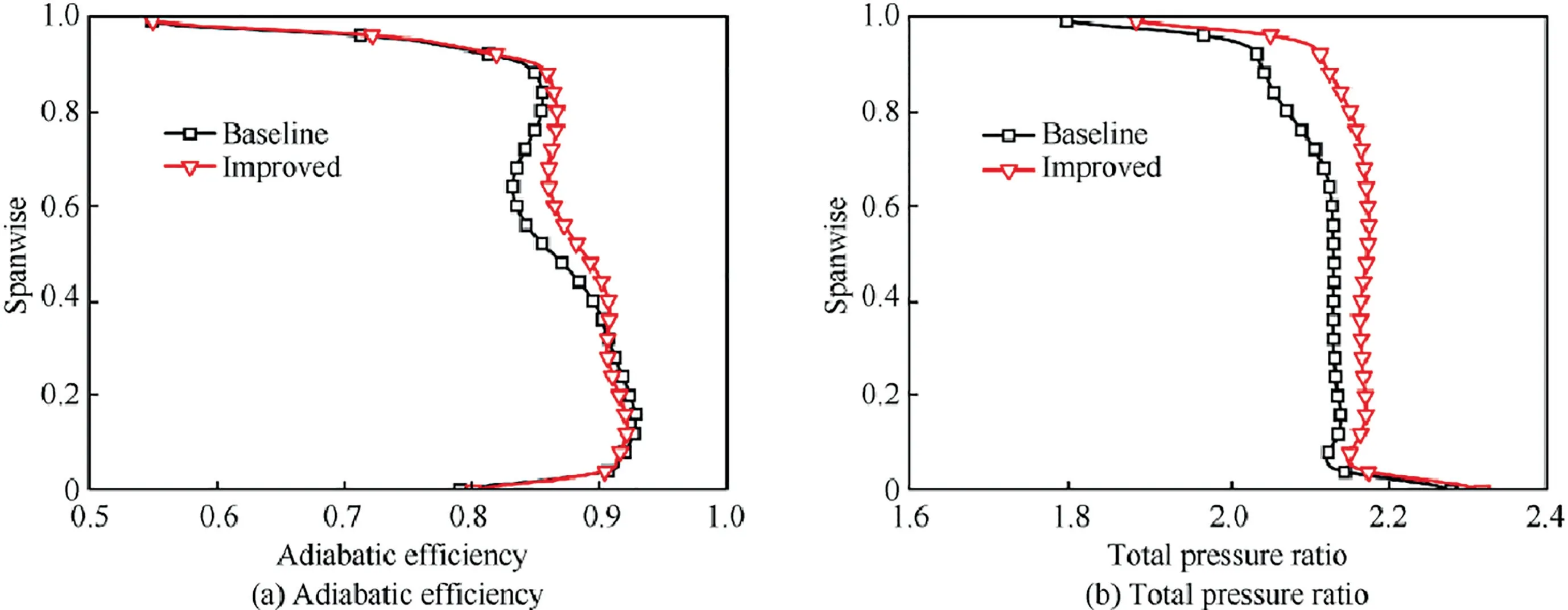
Fig.12 Spanwise distributions of adiabatic efficiency and total pressure ratio for two rotors at design point.
4.2.Flow physics of SCB at design rotor speed
Although RANS method is unable to provide some exact information within boundary layer in the flow fields of interest due to lack of prediction accuracy,results attained from RANS can display the trend of qualitative variation.Thus,comparisons and analyses based on RANS simulation results are feasible and reasonable for revealing and understanding the flow physics of SCB.It is obviously observed that spanwise distributions of aerodynamic performance parameters of improved model exceed those for baseline blade,as described in the previous section.Spanwise shock waves configuration along blade of both models are shown in Fig.13.Since geometries for two blades are distinct each other,modified profiles may improve local flow field for less aerodynamic loss.It is very clear in Fig.13 that each stronger shock wave foot at mid blade span and above is substituted for each family of compression waves and a weaker shock wave foot,and the shock-impingement point on blade suction surfaces move downstream about 3.23%,5.72%,3.0% and 2.68% of blade local chord at 40%,60%,80% and 90% blade spans respectively.The shock wave configuration is almost unchanged near the blade root.
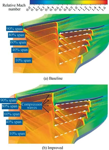
Fig.13 Spanwise shock wave configuration of both models.
In order to reveal more detailed information on distinct difference of flow field along the blade span for both rotor blades intuitively,relative Mach number contours at 10%,40%,60%and 90% of blade spans within blade passage are show in Fig.14.For the blade root,the pre-shock Mach number is low,and boundary layer separation at the trailing edge of blade is mainly due to the excessive airflow deflection.About mid blade span and above,it is easily seen that SCB structure just alters local flow field ahead of passage shock foot and exerts much limited effect on Mach number distribution further upstream and in main flow domain.It is the flow physics of SCB that ramp structure of SCB modified geometry of blade surfaces with negative curvature generating series of compression waves to reduce pre-shock Mach number with much less aerodynamic loss.It is found that pre-shock Mach number degraded 11.4%,10.5% and 11.7% at 40%,60% and 90%blade spans respectively.It can be clearly discovered that SCB structure pushed downstream the boundary layer separation initial position induced by shock wave and reduced shockinduced boundary layer separation region significantly,especially at 60% blade span.It is considered via analysis that SWBLI occurred in blade passage are attenuated due to weakening strength of shock wave foot and that both loss from shock wave and its interaction with boundary layer has been constrained for higher aerodynamic efficiency.
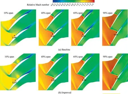
Fig.14 Relative Mach number contours at 10%,40%,60% and 90% blade spans at design point.
Analyses on the limited streamline at the whole blade suction surface and the section streamline (of blade root,mid span,and top span) have also been executed at design operating point.It can be found in Fig.15 that there exists a curved shock surface in the whole blade passage span and induced boundary layer separation line corresponds to the radical location of passage shock impingement.In addition,it is also distinguished from the slice streamline that boundary layer reattachment and re-separation may occur below 60% spans and that re-separation may appear at trailing edge above blade middle spans.This is attributed to large adverse pressure gradient induced by shock wave and great variation of curvature on suction side after passage shock.Compared to baseline blade,streamlines of improved model shows quite different.The region of boundary layer separation induced by shock occupies approximately above 20% spans on suction surface,and location of boundary layer separation line moves downstream along the streamline.The slice streamline shows that no boundary layer reattachment is formed on the blade suction surface of the improved model.The delay of boundary layer separation and the reduction of separation region indicate that the SCB structure can effectively weaken passage shock foot and promote aerodynamic performance of transonic compressors.

Fig.15 Limited streamline and section streamline distributions of two rotors at peak efficiency point.
Fig.15 also depicts transport trend of low-momentum fluid within boundary layer in the region of SWBLI.Driven by radial centrifugal force,low-momentum fluid in boundary layer drifts from hub to blade tip.Radial flow separation loss on blade surface can be shown as static entropy contours in Fig.16,where PS is the pressure surface and SS the suction surface.In sections ranging from 65%to 80%axial chord,separation zone induced by passage shock on blade suction surface for both two blades gradually increases along streamline group,and radial separation fluids of the improved rotor significantly lowers than baseline blade,implying that drastic curvature change of baseline rotor on suction surface after passage shock leads to intensification of radial separation along streamline and that SCB structure can also significantly suppress radial transport of low-momentum fluid within boundary layer.
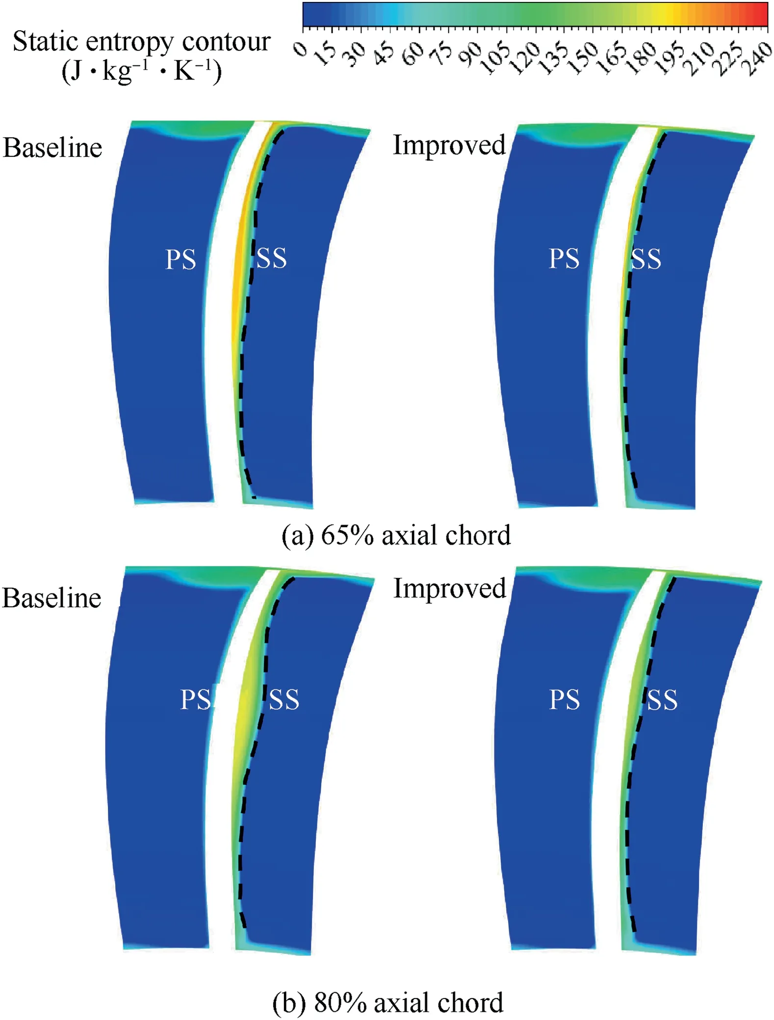
Fig.16 Static entropy contours at 65% and 80% axial chord section.
Additionally,the blade loading distributions at different blade spans for two rotors at design point are shown in Fig.17.It can be seen from the blade root to the tip that a large adverse pressure gradient induced by strong passage shock appears on the suction surface of baseline rotor.Nevertheless,this large adverse pressure gradient vanishes due to the SCB structure of improved model,and pressure rises near the passage shock foot on the blade surface consists of two parts,first of which is produced by the compression waves originated from ramp of the SCB,and second of which is caused by the weaker incident passage shock foot.For the 60% blade span with the significant improvement in aerodynamic performance along spanwise direction,the static pressure ratio induced by single passage shock is 1.85 for baseline blade,while both parts of static pressure ratio induced by compressor waves and weaker incident passage shock foot are 1.26 and 1.46 respectively for improved model,indicating that pressure rise of compression waves accounts for about 30%of total pressure ratio.In addition,static pressure distributions on concave surface of ramp is basically linear,and only a little deviation is represented at the initial position of the SCB between simulation results and expected values of constant adverse pressure gradient,indicating feasibility of design method.The main reason for this deviation lies in not taking into account the radial flow driven by centrifugal force in design method with constant adverse pressure gradient for each blade span.More researches efforts on profile design considering radial flow are anticipated in the near future.Variation of shock wave configuration near SCB helps to reduce the adverse pressure gradient due to single strong shock wave in compressor rotor blades.Moreover,the static pressure behind passage shock near suction surface of improved model is also higher than baseline blade,which is ascribed to smaller flow separation in this region.Thus,it can be concluded SCB structure helps to produce moderate adverse pressure gradient by dividing pressure rise induced by strong passage shock into two parts,and suppresses flow separation effectively in this transonic compressor.
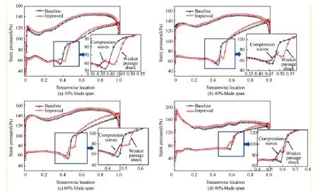
Fig.17 Streamwise blade loading distribution at different blade spans at design point.
Relative Mach number contours at 10%,40%,60% and 90% spans of two rotors near stall point are shown in Fig.18,indicating that passage shock moves away from leading edge of blade and forms a stronger detached shock near stall point.Since shock-impingement position of detached shock is located ahead of SCB,little effect could exert on flow field ahead of detached shock for improvement,and flow field characteristics at the front of detached shock for both rotor blades are almost the same.However,boundary layer separation induced by detached shock of the rotor with SCB is greatly diminished,and separation structure is significantly different from that of baseline rotor.About mid blade span and above,boundary layer separation of improved model is divided into two parts by plateau section of the SCB structure,first part of which is formed at ramp of the SCB structure(black elliptic line),and second part of which grows at the tail section of the SCB structure.Accumulation of low-momentum fluid in boundary layer is suppressed obviously by the crest plateau of the SCB structure.The reason for this is due to the crest plateau of SCB obstructs low-momentum fluid transported to the downstream in boundary layer,making the boundary layer separation reattachment in advance.Boundary layer re-separation of improved model is formed mainly due to excessive airflow deviation at the end of tail section of the SCB.
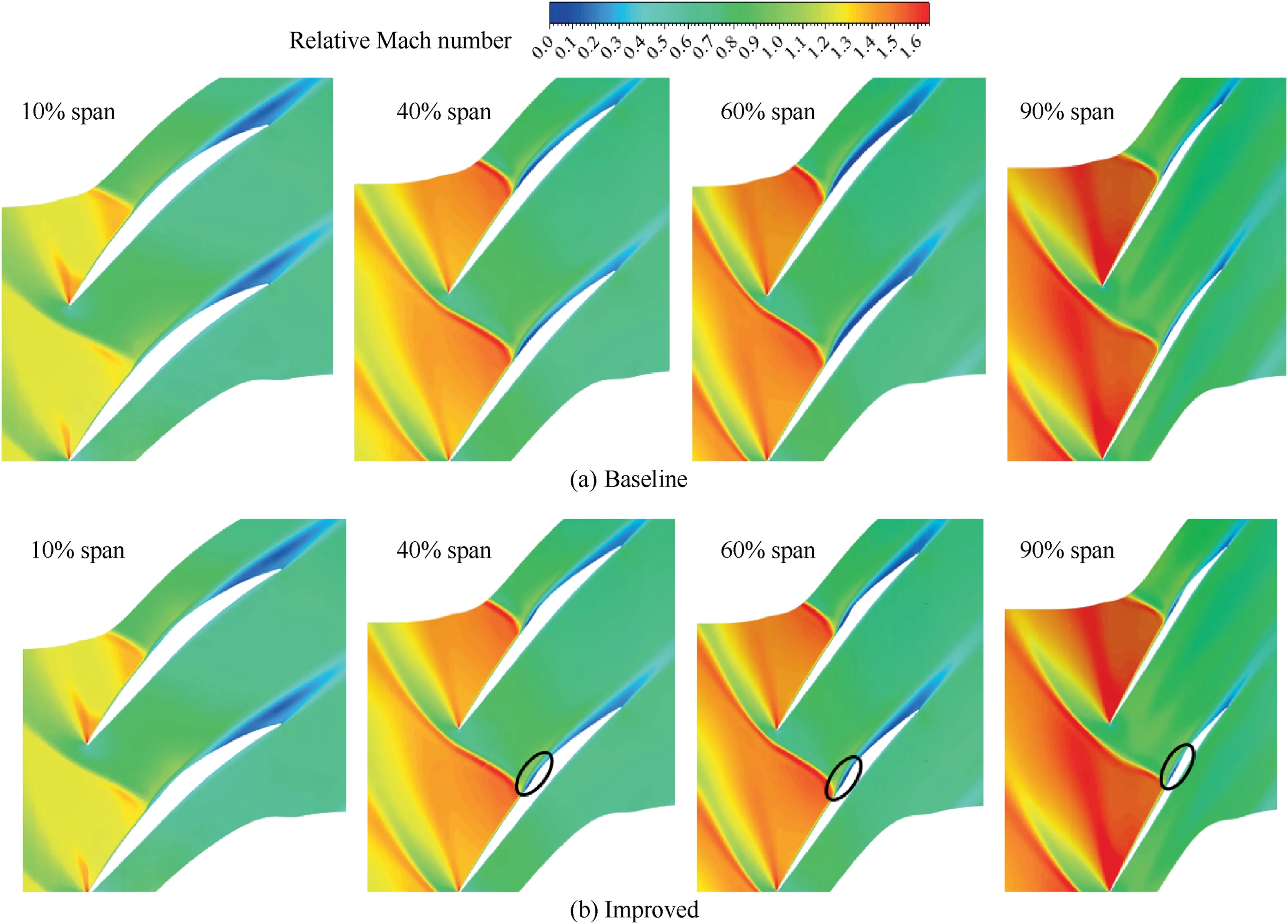
Fig.18 Relative Mach number contours at 10%,40%,60% and 90% blade spans near stall point.
Fig.19 shows the limited streamline and slice streamline(of blade root,mid span,and top span) distributions on suction surface near stall point of two rotors,which indicates that the chordwise and spanwise positions of the separation line induced by detached shock are same for both two rotor blades.The reason for this is mainly attribute to impingement position of detached shock located front of SCB,which is beyond action range of SCB structure near stall point.Nevertheless,the limited streamline and slice streamline indicate that the behaviors of boundary layer reattachment and re-separation behind detached shock are different obviously of two blades.Boundary layer reattachment near suction surface occurs downstream away from detached shock in less than 50%spans of baseline blade,and re-separation generates near the trailing edge of blade.The boundary layer re-separation may be due to great variation of curvature on suction side near the trailing edge of blade.By contrast,boundary layer reattachment in advance of improved model occurs in the crest plateau section of SCB along whole blade span,and re-separation arises at the position of tail section of SCB on suction surface.The results are basically consistent with the Mach number distributions in Fig.18.

Fig.19 Limited streamline and section streamline distributions of two rotors near stall point.
Fig.19 displays movement trend of low-momentum fluid in boundary layer on blade suction surface near stall point.Boundary layer separation fluid behind detached shock transport outward from hub to blade tip driven by centrifugal force for both two rotors.Compared with baseline blade,the first part separation fluid of improved model moves upward in group of blade tip along ramp section of SCB,which is mainly attributed to crest plateau of SCB hindering evolvement downstream of boundary layer low-momentum fluid.Static entropy contours in Fig.20 indicate that chordwise and spanwise separation fluid within boundary layer is greatly diminished for improved model with SCB,and that separation loss decreases obviously.
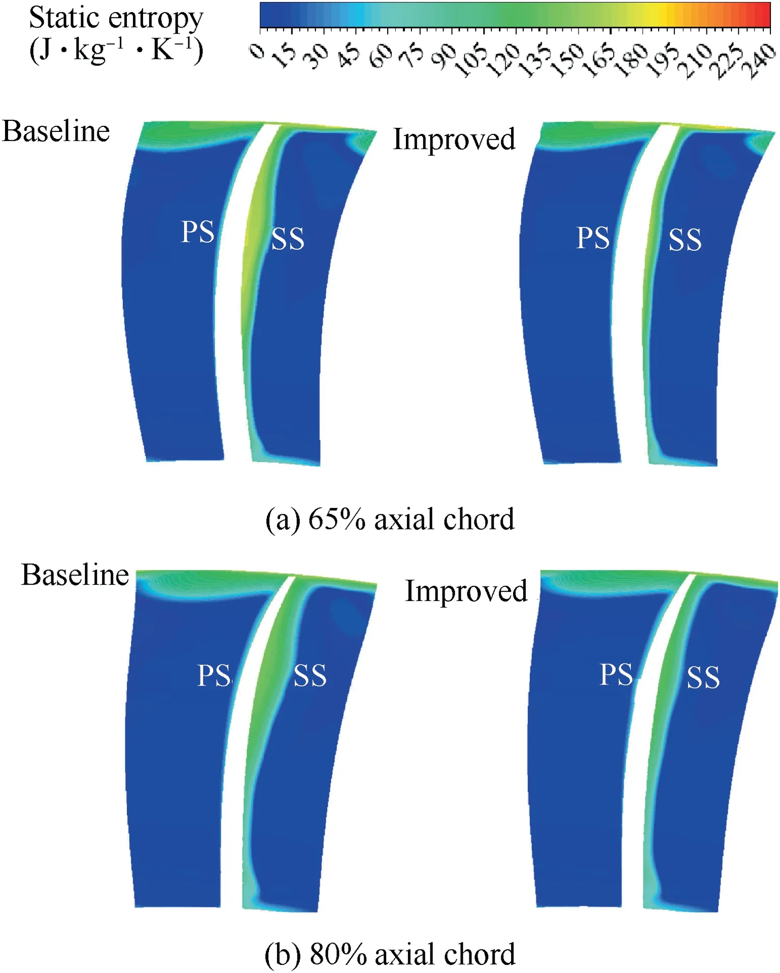
Fig.20 Static entropy contours at 65% and 80% axial chord section near stall point.
4.3.Compatibility of SCB at off-design rotor speed
The overall performances of both rotor blades at off-design conditions are shown in Fig.21,which indicates that slightly negative effect may occur with decrease of rotation speed.Overall performance of improved model surpasses baseline blade near peak efficiency point at 95%design rotation speed,and adiabatic efficiency and total pressure ratio are lifted by 0.41%and 0.83%respectively.However,aerodynamic performance of modified models lightly goes down at 90%,80%and 70% design rotation speed.The adiabatic efficiency of the improved rotor is reduced by 0.29%,0.32%and 0.15%respectively at peak efficiency point,and total pressure ratio at corresponding operating point is reduced 0.15%,0.11% and 0.09%as well.With further decrease of rotation speed,overall performance of two models almost remains consistent below 60% design rotor speed.
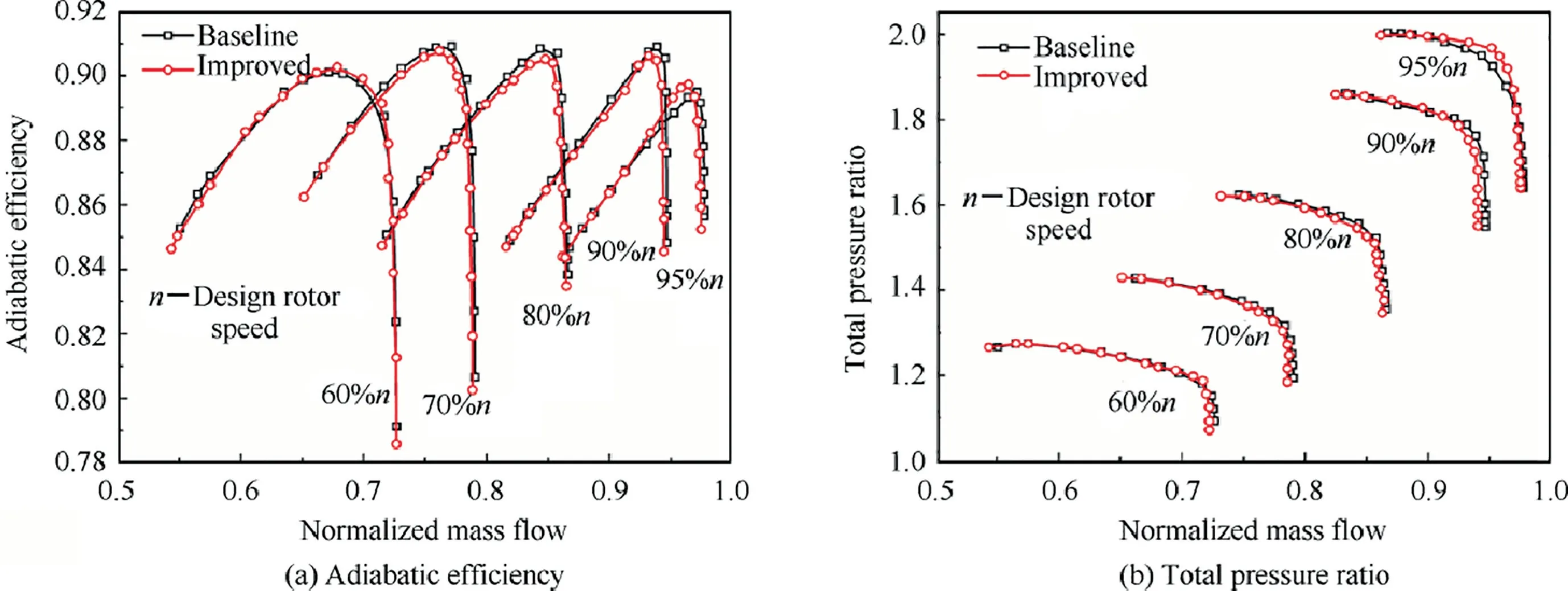
Fig.21 Overall performance of two rotors at off-design rotation speed.
Relative Mach number contours at 60%blade span at 95%design rotor speed for both models are shown in Fig.22,illustrating that passage shock of baseline rotor blade is remains strong,and boundary layer separation induced by shock appears near suction side.By contrast,both strength of passage shock and region of boundary layer separation have decrease for improved model.The reason for this is mainly due to compression waves reduce flow velocity before passage shock foot,and corresponding Mach number declines from 1.47 to 1.29.Its mechanism is the same as improved model at design rotor speed.
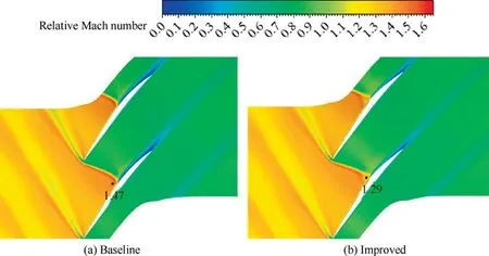
Fig.22 Contours of relative Mach number at 60% blade span at 95% design rotation speed.
In order to further seek source for slight drops of improved model aerodynamic performance at 70%-90% design rotor speed.Fig.23 shows spanwise distributions of adiabatic efficiency and total pressure ratio at 80% design rotor speed of both blades at peak efficiency point.Aerodynamic performance of two rotor blades are almost the same at 50% spans below,however,improved model is slightly lower than baseline blade at 50%-90% of blade span.Relative Mach number contours at 60% blade span of both models near peak efficiency point at 80% design rotor speed are shown in Fig.24.Detached shock is weaker for baseline blade and could not induce boundary layer separation.However,a local supersonic region appears on crest plateau of SCB on suction surface for improved model,and losses due to boundary layer lowmomentum fluid near blade trailing edge appear larger than baseline blade.With the further decrease of rotary speed,relative Mach number contours at 60% design rotor speed near peak efficiency point at 60% blade span are shown in Fig.25.The detached shock disappears,and flow in whole blade passage becomes subsonic.Relative Mach number contours of both two models are basically the same.Therefore,aerodynamic performances of both two rotor blades are almost the same under 60% design rotor speed.
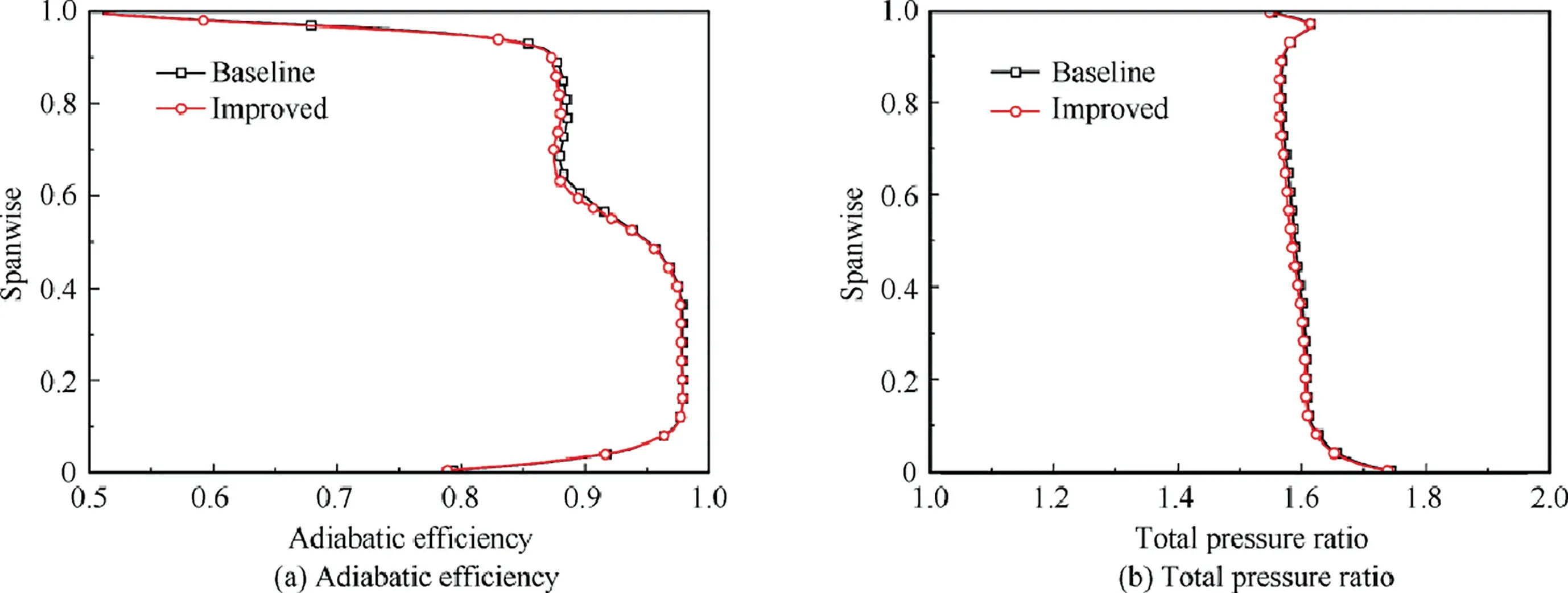
Fig.23 Spanwise distributions of adiabatic efficiency and total pressure ratio at 80% design rotor speed for two rotors.
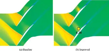
Fig.24 Relative Mach number contours near peak efficiency point at 80% design rotation speed for two rotors (60% span).
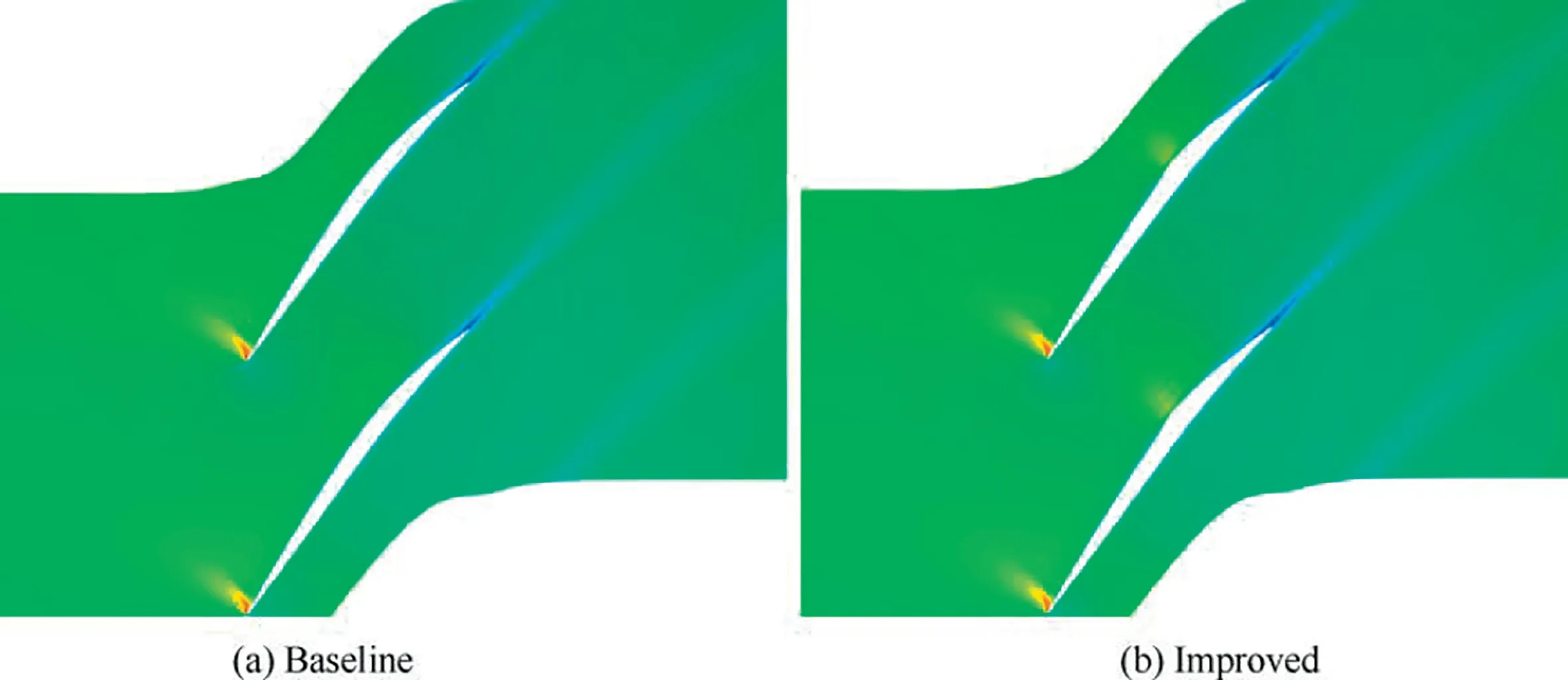
Fig.25 Relative Mach number contours near peak efficiency point at 60% design rotation speed for two rotors (60% span).
5.Conclusions
In order to diminish aerodynamic loss induced by shock waves and SWBLI inside transonic compressor blade passages,an aerodynamic performance promotion approach employing SCB technique has been executed on Rotor 37 blade suction surfaces for acknowledgment and comprehension on flow physics of SCB.The windward profile of SCB has been constructed following regulation of constant adverse pressure gradient along blade suction surface and is located ahead of passage shock foot at design rotor speed.Numerical investigations on flow fields of baseline (Rotor 37 blade profile) and improved models have been implemented by means of RANS method at various rotatory speeds,and the corresponding flow fields analyses have been dealt in detail for revealing flow physics of SCB as following:
(1) At peak efficiency point (95%-100% design rotation speed),the passage shock foot in baseline blade passage can be substituted for a family of compression waves and weaker shock foot,resulting in weaker flow separation loss due to decrease of shock strength.In addition,the strong adverse pressure gradient induced by passage shock is divided into two parts by the SCB,which benefits to create moderate adverse pressure gradient as well as suppression of radially outward flow of lowmomentum fluid within boundary layer.
(2) Below the design conditions (60%-95% design rotation speed),there exists a local supersonic region behind plateau of SCB on improved blade suction surface implying more loss of low-momentum fluid in the boundary layer near trailing edge than baseline model.
(3) At less rotational speeds (below 60% design rotation speed),the overall performance and flow fields of both rotors are almost same due to subsonic flow in both of blade passages.
It should be noted that the radially outward flow is not taken into account in design method of windward side of SCB.Furthermore,the windward profile of SCB may cover larger rotational speed range with penalty of less performance promotion at design rated speed.Therefore,the design method and optimum extent to balance as larger rotor speed range and better aerodynamic performances as possible will be investigated in consequent research.
The authors declare that they have no known competing financial interests or personal relationships that could have appeared to influence the work reported in this paper.
The authors sincerely thank for receipting the funding from the National Key Research and Development Program of China (No.2016YFB0901402) and the Key Project of National Natural Science Foundation of China(No.51790513).
 Chinese Journal of Aeronautics2022年2期
- Chinese Journal of Aeronautics的其它文章
- Pressure-induced instability and its coupled aeroelasticity of inflated pillow
- Adjoint boundary sensitivity method to assess the effect of nonuniform boundary conditions
- Transit time difference and equal or non-equal transit time theory for airfoils with lift
- A boundary surrogate model for micro/nano grooved surface structure applied in turbulence flow control over airfoil
- Nonlinear uncertainty quantification of the impact of geometric variability on compressor performance using an adjoint method
- High precision and efficiency robotic milling of complex parts:Challenges,approaches and trends
