Modified robust optimal adaptive control for flight environment simulation system with heat transfer uncertainty
Meiyin ZHU, Xi WANG, Xitong PEI, Song ZHANG, Zhihong DAN,Nannan GU, Shubo YANG, Keqiang MIAO, Huairong CHEN,Jiashuai LIU
a School of Energy and Power Engineering, Beihang University, Beijing 100083, China
b Collaborative Innovation Center for Advanced Aero-Engine, Beijing 100083, China
c Science and Technology on Altitude Simulation Laboratory, AECC (Aero Engine Corporation of China) Sichuan Gas Turbine Establishment, Mianyang 621000, China
KEYWORDS Altitude ground test facilities;Flight environment simulation system;Heat transfer;Model reference adaptive control;Optimal control modification;Uncertainty
Abstract To solve the rapid transient control problem of Flight Environment Simulation System(FESS)of Altitude Ground Test Facilities(AGTF)with large heat transfer uncertainty and disturbance, a new adaptive control structure of modified robust optimal adaptive control is presented.The mathematic modeling of FESS is given and the influence of heat transfer is analyzed through energy view.To consider the influence of heat transfer in controller design,we introduce a matched uncertainty that represents heat transfer influence in the linearized system of FESS. Based on this linear system, we deduce the design of modified robust optimal adaptive control law in a general way.Meanwhile,the robust stability of the modified robust optimal adaptive control law is proved through using Lyapunov stability theory. Then, a typical aero-engine test condition with Mach Dash and Zoom-Climb is used to verify the effectiveness of the devised adaptive controller. The simulation results show that the designed controller has servo tracking and disturbance rejection performance under heat transfer uncertainty and disturbance;the relative steady-state and dynamic errors of pressure and temperature are both smaller than 1% and 0.2%respectively. Furthermore,the influence of the modification parameter γ is analyzed through simulation. Finally, comparing with the standard ideal model reference adaptive controller, the modified robust optimal adaptive
Nomenclature
D thickness of long tube, m
H height, km
L length of long tube, m
Ma Mach number
Q heat, J
˙Q heat transfer rate between FESS and surroundings, J/s
R gas constant, J/(kg∙K)
T temperature of FESS, K
Tintemperature of the inlet, K
Tgtemperature of gas in the long tube, K
Tjtemperature of the tube j, K
Twtemperature of FESS wall, K
V cubage of FESS, m3
cinaverage flow velocity of the inlet, m/s
coutaverage flow velocity of the outlet, m/s
cPspecific heat at constant pressure, J/(kg∙K)
ctspecific heat of the long tube, J/(kg∙K)
h enthalpy of air in FESS, J/kg
hfconvection heat transfer coefficient, W/(m2∙K)
hinenthalpy of air in the inlet, J/kg
k conductivity of the long tube, W/(m∙K)
˙minmass flow rate of the inlet, kg/s
˙moutmass flow rate of the outlet, kg/s
p pressure of FESS, Pa
pinpressure of the inlet, Pa
r0inner radius of the long tube, m
rjradius of the tube j
ρ density of the long tube, kg/m3
α thermal diffusivity of the long tube
1. Introduction
Altitude Ground Test Facility (AGTF) is a ground test platform that can simulate the intake and exhaust conditions of aero-engine without the influence of weather and time.1AGTF is responsible for most of the tests of aero-engines,and plays a vital role in the research and development of these engines.1,2With the study and developing of high performance aeroengines like Turbine-Based Combined Cycle (TBCC) engine,more and more high requirement tests (e.g. mode transition test of TBCC engines, rapid acceleration and deceleration tests)need to be conducted in AGTF. These test requirements needs AGTF having the corresponding test ability.3The goal of AGTF is to test the aero-engines as close to the flight conditions(Mach number and altitude)which will be encountered during flight as possible.4,5The inlet conditions(total pressure and temperature) are simulated by the Flight Environment Simulation System (FESS) where the air has the same total temperature and pressure with the required inlet conditions.5Whereas, in practice, the huge pipe network system of FESS will influence the pressure and temperature control of FESS especially in rapid transient engine test through the heat transfer between FESS and the pipe. The influence of heat transfer by the pipe network system is a large uncertainty for FESS.However,the current control methods(PI gain scheduling control,6,7linear parameter varying μ synthesis control,5and μ method with extended Kalman filter8) for the AGTF control system do not consider the influence of heat transfer uncertainty in control design.To deal with this uncertainty in FESS,adaptive control is used.
Adaptive control is a non-linear control method that can effectively deal with uncertainty of the system. Adaptive control has gained much attention from researchers recently.Adaptive theory has been applied in many engineering areas such as aerospace,9,10aircraft,11–13UAVs,14,15fluid systems,16etc. Adaptive control has the capability to process uncertainties and to improve fault tolerance of a control system.17However, adaptive control still encounters difficulties in providing robustness when system with large uncertainties.18During the last few years, many adaptive control methods have been researched. For example, various adaptive fuzzy controllers are designed for nonlinear systems.19,20Furthermore, many adaptive neural control methods are proposed to solve uncertainty in nonlinear systems.21–23Also,many Model Reference Adaptive Control(MRAC)techniques have been developed to provide robustness under large uncertainties.12,24,25In the traditional MRAC scheme, the tracking performance is usually inversely proportional to the adaptive gain.Nontheless,a high adaptive gain can cause high-frequency oscillations which can arouse unmodeled dynamics that could have a negative impact on the stability of the MRAC law.26To improve robustness of MRAC, many modifications were developed through adding damping to the adaptive law to decrease high-frequency oscillations. The σ modification27and ε modification28are two renowned robust modification techniques. Other methods like the projection and the dead-zone method are also adopted to increase robustness of adaptive law. In addition, a large number of new advanced robust adaptive methods are developed,e.g. the adaptive loop recovery,29composite MRAC,30L1adaptive control,31and Optimal Control Modification(OCM).32In 2008, Nguyen et al. first proposed the OCM method and this method has been rigorously validated in flight simulation experiments and NASA F/A-18A aircraft flight tests.32–35This method combines high performance with robustness for system with large uncertainty. However, this method has not used in FESS control system. Therefore, in order to consider the influence of heat transfer in controller design to improve control precision of pressure and temperature of FESS, we propose a new Modified Robust Optimal Adaptive Control (MROAC) structure with heat transfer uncertainty and disturbance. The main contributions of this paper can be summarized as
(1) It represents the first time that the heat transfer influence of FESS is considered in controller design by using a matched uncertainty with MROAC.
(2) The proposed MROAC law provides a solution to improve control precision of system with heat transfer uncertainty and disturbance.
2. Flight environment simulation system modeling
Fig. 1 depicts the structure schematic drawing of FESS. The FESS mainly comprises control valve 1,control valve 2,mixer,flow straightener subsystem,and other connecting pipes,which together provides the desired inlet conditions (total pressure and temperature)to the test aero-engine.FESS has two inlets:Inlet 1 is hot flow,and its mass flow rate is regulated by control valve 1; Inlet 2 is cold flow, whose mass flow rate is regulated by control valve 2.The main function of the mixer is to mix the hot and cold flow uniformly. The flow straightener subsystem makes the mixed flow more evenly, smoothly, and steady.
In order to describe the physical process of the air in FESS by mathematical model, the structure schematic diagram of FESS in Fig.1 is equivalent to a volume model with two inlets and one outlet by using a specific equivalence principle. The equivalence principle ensures the equivalent volume model has the same physical cubage, metal mass, and heat transfer surface area as the actual FESS. The schematic drawing of the equivalent volume model is illustrated in Fig.2.36We suppose that the mean properties within the FESS are equal to the properties (pressure, temperature, density) at the outlet.5
We can find the derivation of the nonlinear system of FESS in Refs. 2,5, and the results are as follows:
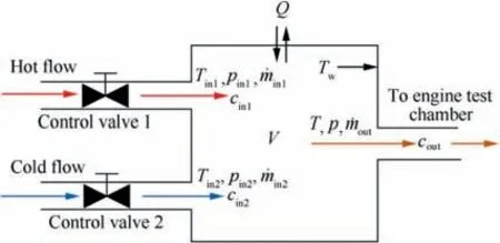
Fig. 2 Equivalent volume model schematic diagram of FESS.36
As we can see in Fig. 1, FESS has a large amount of metal mass, which will influence the pressure and temperature control of FESS especially in fast transient engine test through the heat transfer between FESS and metal mass.Thus,we need to establish the heat transfer model of FESS and consider it into controller design to improve the control precision and response speed of pressure and temperature of FESS. Because the structure of FESS is a ring cavity and FESS is wrapped with insulation,the heat transfer between FESS and the metal mass can be equivalent to a heat transfer model of a long tube with insulation boundary condition. Then, a long tube with inner radius of r0,thickness of D,length of L,density of ρ,conductivity of k,and specific heat of ct.The direction of the conduction is along the radial direction is considered.36The long tube is divided into N+1 thin tube by using nodes 0, 1, ...,j–1, j, j+1, ..., N–1, N, which is depicted in Fig. 3.
We can find the derivation of the heat transfer of the long tube in Refs. 2,5. The resulting temperature differential equations of the N+1 thin tube are:
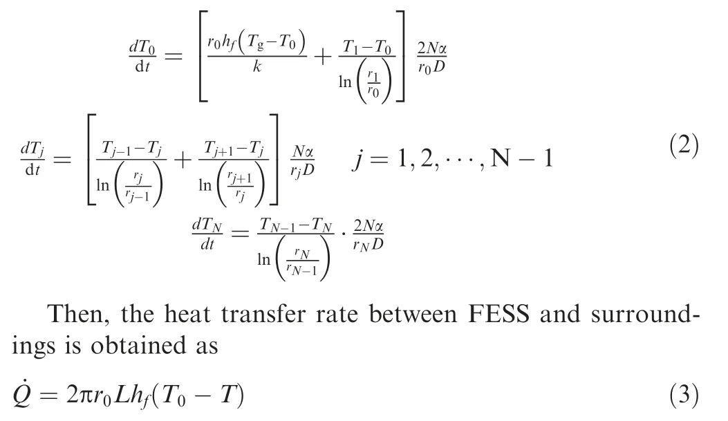


Fig. 1 Structure schematic diagram of FESS.
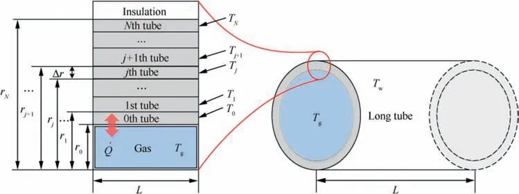
Fig. 3 Heat transfer model schematic diagram of long tube.
Before entering the stage of controller design, we need to linearize the nonlinear differential Eq.(1).We define the state,control input, and disturbance of the FESS as
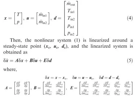
Because at the equilibrium state, the temperature of FESS is equal to temperature of pipe, which means the heat transfer rate between FESS and surroundings at the equilibrium state is zero.Therefore,the linearized system(5)does not contain any information about the heat transfer.However,in any transient process of FESS, when certain amount of control flows (hot flow and cold flow) enter FESS, because of the existence of heat transfer, FESS would lose or obtain extra energy from surroundings. Hence, from the viewpoint of energy analysis,the actual energy enter FESS is not equal to the energy provided by control flows(the actual energy when no heat transfer exists),which means the heat transfer energy should be considered as extra control inputs for FESS. According to Eqs. (1)and(3),the influence of heat transfer on temperature and pressure of FESS can be described as follows:

where, fT(T, p) and fp(T, p) denote the influence functions of heat transfer on temperature and pressure of FESS respectively.
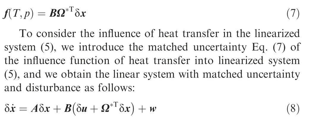
where w=Eδd ∈R2denotes the bounded exogenous disturbance.Then,we will deduce the design of modified robust optimal control adaptive control law based on the structure of linear system (8) in a general way.
3. Modified robust optimal adaptive law
Consider a linear system with a matched uncertainty and disturbance as
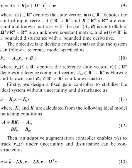
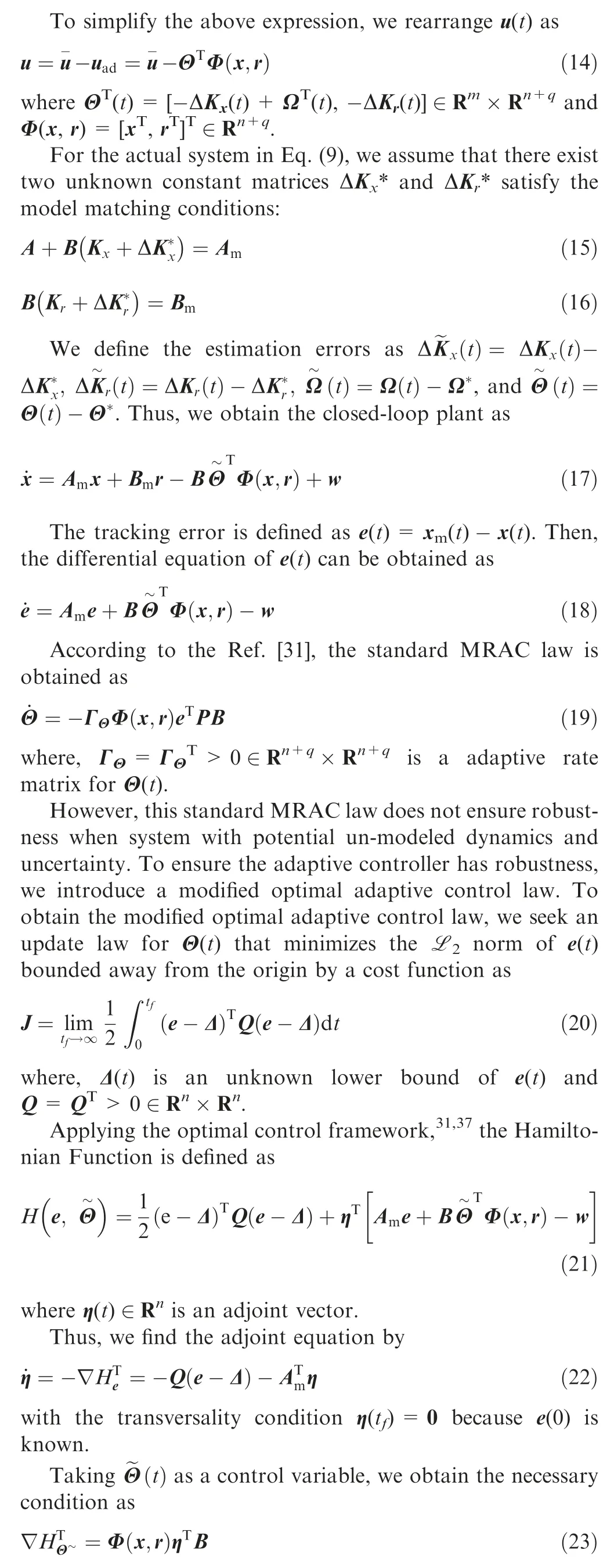
Then,we obtain the modified optimal adaptive control law from the gradient update law as
Fig.4 illustrates the constructive and schematic diagram of the modified optimal control adaptive control system. In Fig. 4, we can see that this adaptive system includes five subsystems,which are uncertain plant,reference model,fixed controller, adaptive controller, and modified optimal adaptive control law.The modified optimal adaptive control law combines with the adaptive and fixed controller together ensure the system have robustness with matched uncertainty and disturbance. Now, we need to demonstrate the designed modified optimal adaptive control law is stable and achieve uniformly bounded tracking error.
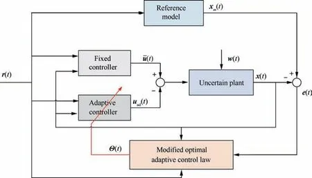
Fig. 4 Constructive and schematic diagram of modified optimal control adaptive control system.
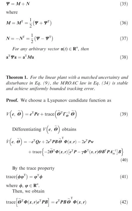
Lemma 1.38For any square real matrix Ψ ∈Rn×Rn,it can be decomposed into a symmetric matrix M and anti-symmetric matrix N

4. Flight environment simulation system example
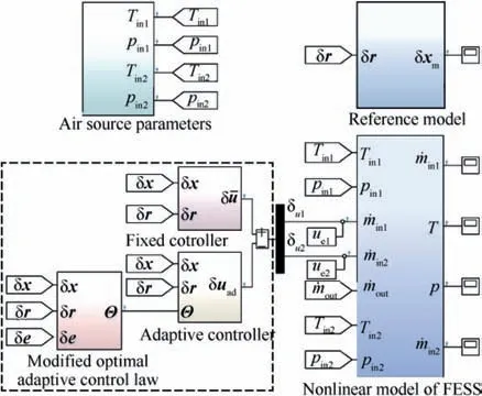
Fig. 5 Simulation platform of FESS.
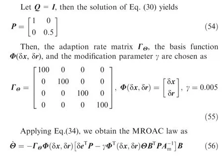
We apply the proposed MROAC law to a flight environment simulation system. Firstly, we take a typical equilibrium point of FESS as an example to design the modified robust optimal adaptive controller.Secondly,to verify the effectiveness of the devised adaptive controller,the simulation platform of FESS is established by using the MathWorks Simulink simulation tool,39which is illustrated in Fig. 5. Then, the servo tracking and disturbance attenuation performance of the devised adaptive controller is verified by a typical aero-engine test.Furthermore,the influence of the modification parameter γ is analyzed through simulation. Finally, we compare the simulation result of the ideal model reference adaptive controller with the simulation result of the proposed modified robust optimal adaptive controller in this paper.
4.1. Modified robust optimal adaptive controller design
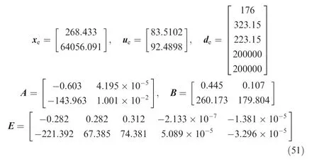
The necessary modeling parameters of the FESS are illustrated in Table 1.We take the typical steady-state point(flight condition: H=5 km, Ma=0.5) of FESS as an example to devise the modified robust optimal adaptive controller.The nonlinear differential Eq.(1) is linearized around this steady-state point,and the steady-state values and linearized matrix are obtained as follows
Then, according to the performance requirements of pressure and temperature of FESS, we hope the closed-loop control of pressure and temperature should have the characteristics of first order functions with time constant equal to 2 s and 1 s respectively. Thus, the reference model is specified as
When all was ready, Prince Almas set out for home, taking with him Jamila, and Dil-aram and Gul, daughter of Taram-taq, and the wicked Mihr-afruz, and all the belongings of the four, packed on horses and camels, and in carts without number
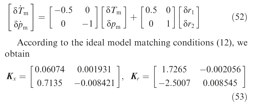

Table 1 Necessary modeling parameters of FESS.
4.2. Simulation results
To verify the effectiveness and superiority of the modified robust optimal adaptive controller,a series of simulation analysis is conducted in the simulation platform depicted in Fig.5.Firstly, we suppose a representative aero-engine test process with Mach Dash and Zoom-Climb to verify servo tracking and disturbance attenuation performance of the devised adaptive controller.The test process:it is supposed that the airplane accelerates from Mach 0.5 to 1.0 with the same height 5 km within 60 s (Mach Dash), and then climbs from 5 km to 10 km with Mach 1.0 within 60 s(Zoom-Climb).Fig.6 depicts the setting conditions of the test aero-engine.
4.2.1. Typical engine test condition performance verification
Using the simulation platform of FESS in Fig. 5 and the test condition in Fig. 6, we verify the servo tracking and disturbance attenuation performance of the devised adaptive controller through simulation analysis.
Fig.7(a)shows the histories of temperature simulation,and the black line denote reference temperature (TReference), the blue dotted line denote the response temperature of the reference model(Tm),the red dash dot line denote the temperature of FESS (TFESS), and the magenta dotted line represent the wall temperature of FESS (Tw). In Fig. 7(a), the temperature of FESS can follow the reference temperature even though the large temperature difference between TFESSand Tw,which means the heat transfer rate between FESS and surroundings is very large; from the partial amplified graph, the relative steady state error is smaller than 0.15% and the relative dynamic error is smaller than 0.65%,which means the devised modified robust optimal adaptive controller has good robust performance on temperature.
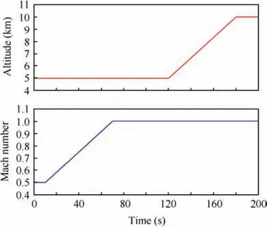
Fig. 6 Setting conditions of test aero-engine.
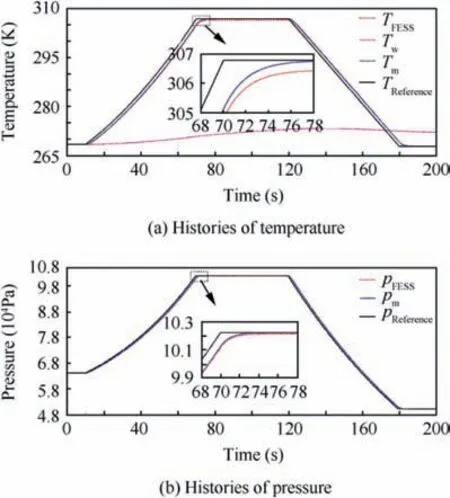
Fig. 7 Histories of temperature and pressure simulation.
Fig.7(b)illustrates the histories of pressure simulation,and the black line denote reference pressure (pReference), the blue dotted line denote the response pressure of the reference model(pm), and the red dash dot line denote the pressure of FESS(pFESS). In Fig. 7(b), the pressure of FESS also can follow the reference pressure; from the partial amplified graph, the relative steady state error is smaller than 0.1%and the relative dynamic error is smaller than 0.95%,which means the devised modified robust optimal adaptive controller has good robust performance on pressure.
Fig. 8 depicts histories of the heat transfer rate in FESS during the engine test.From Figs.7 and 8,we can see that with the temperature of FESS rapidly increase from around 268 K to 307 K within one minute,the wall temperature of FESS also gradually increase but very slow and the heat transfer rate between FESS and metal mass continually rise;when the temperature of FESS rapidly drops to 267.8 K, the wall temperature Twis larger than TFESSand the heat transfer from metal mass to FESS. It means the heat transfer in FESS has great influence on temperature control of FESS especially in fast temperature change. Thus, it is necessary to take into account this heat transfer influence in controller design.
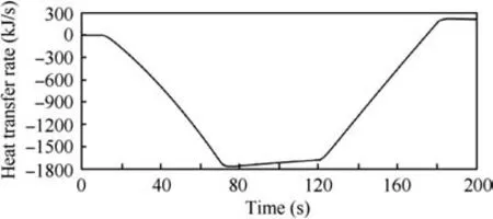
Fig. 8 Histories of heat transfer rate in FESS.
The control outputs of the devised adaptive controller during the engine test is shown in Fig.9.In Fig.9,when the temperature of FESS rapidly increase, the adaptive controller output δuad1rapidly decrease to compensate the influence of heat transfer between FESS and surroundings by raising the hot mass flow rate to track the reference temperature, and the adaptive controller output δuad2gradually decrease the cold mass flow rate which further compensate the influence of heat transfer. The simulation results show that the devised adaptive controller can compensate the heat transfer uncertainty and disturbance as we expected.
Fig. 10 shows the histories ˙min1, ˙min2, and ˙moutof FESS during the engine test. In Fig. 10, it can be seen that ˙min1and ˙min2always vary with the change of ˙moutto keep the pressure and temperature of FESS following the reference pressure and temperature in the whole engine simulation test. At the same time, ˙moutchanges a lot during the engine test and it means the disturbance is very large in this engine test, which further indicates that the designed modified robust optimal adaptive controller has good robust performance.
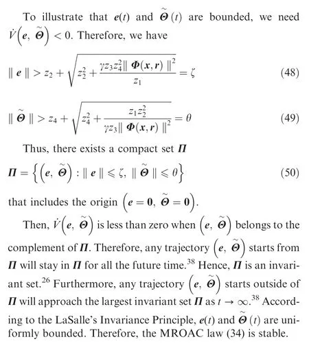
Fig.11 illustrates the histories of||e||2and||Θ||2during the engine test. In Fig. 11, e is the normalized tracking error; we can see that both e and Θ are bounded during the whole engine test, which verifies the validity of Eq. (48) and Eq. (49) in simulation.
4.2.2. Simulation analysis of modification parameter γ
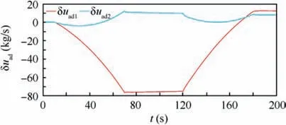
Fig. 9 Control outputs of designed adaptive controller during engine test.
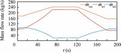
Fig. 10 Histories of ˙min1, ˙min2, and ˙mout during engine test.
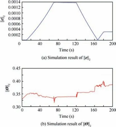
Fig. 11 ||e||2 and ||Θ||2 during engine test.
To analysis the influence of the modification parameter γ to the modified robust optimal adaptive controller, we use the same engine test process and simulation platform but different modification parameter γ to do the simulation. The simulation result of temperature of FESS with different γ is shown in Fig. 12(a). In Fig. 12(a), with the modification parameter γ increasing, the tracking performance of the modified robust optimal adaptive controller decrease but robustness increase,that why the temperature of FESS becomes oscillate around 10 s with γ=0.001 when the heat transfer rate and outlet mass flow rate change a lot. Fig. 12(b) is the simulation result of pressure of FESS with different γ.In Fig.12(b),similar conclusion about the modification parameter γ can be seen as in Fig. 12(a) and the pressure of FESS also becomes oscillate around 10 s with γ=0.001.Thus,the simulation results show that the modification parameter γ is proportional to the robustness and inversely proportional to the tracking error,which is consist with the influence analysis of the modification parameter γ in chapter 3.
Fig.13 depicts the histories of||e||2and||Θ||2with different γ.In Fig.13,it can be seen that both e and Θ are bounded with different γ, which further verifies the validity of Eq. (48) and Eq. (49) in simulation.
4.2.3. Comparison verification
To verify the superiority of the designed modified robust optimal adaptive controller, comparing with the standard ideal model reference adaptive controller, we use the same engine test condition and simulation platform but ideal model reference adaptive controller to do the simulation and compare the results with those of the modified robust optimal adaptive controller.
The comparison result of temperature of FESS is illustrated in Fig. 14(a), and the black line denote reference temperature(TReference), the blue dotted line denote the response temperature of the reference model (Tm), the red dash dot line denote the temperature of FESS controlled by the controller designed in this paper, and the green line denote the temperature of FESS controlled by the ideal model reference adaptive controller. In Fig. 14(a), we can see that the designed modified robust optimal adaptive controller obviously provides better control performance than the ideal model reference adaptive controller does.
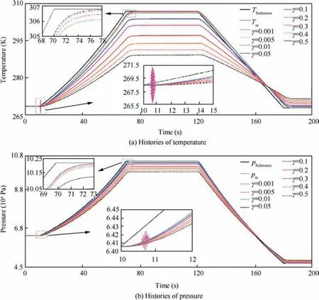
Fig. 12 Histories of temperature and pressure simulation with different γ.
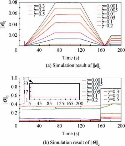
Fig. 13 ||e||2 and ||Θ||2 with different γ.
Fig.14(b)is the comparison result of pressure of FESS,and the black line denote reference pressure (pReference), the blue dotted line denote the response pressure of the reference model(pm), the red dash dot line denote the pressure of FESS controlled by the modified robust optimal adaptive controller,and the green line denote the pressure of FESS controlled by the ideal model reference adaptive controller. In Fig. 14(b),the controller designed in this paper obviously has better control performance than the ideal model reference adaptive controller dose.
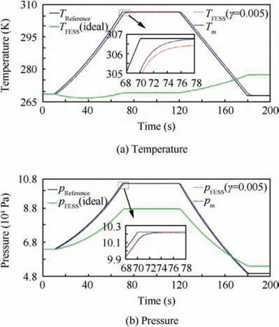
Fig. 14 Comparison results of temperature and pressure of FESS.
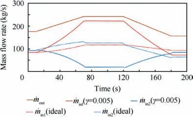
Fig. 15 Comparison result of inlet and outlet mass flow rate of FESS.
Fig. 15 shows the comparison result of mass flow rate of FESS. In Fig. 15, we can see that the ideal model reference adaptive controller cannot regulate ˙min1and ˙min2changing with ˙moutto keep the pressure and temperature of FESS tracking the reference pressure and temperature in the presence of heat transfer uncertainty and outlet mass flow rate disturbance.
Based on the above analysis, with properly choosing the modification parameter γ, the designed modified robust optimal adaptive controller can achieve good robust performance of FESS with heat transfer uncertainty and outlet mass flow rate disturbance and provide better performance than the ideal model reference adaptive controller dose.
5. Conclusions
This paper proposes a new adaptive control scheme of modified robust optimal adaptive control with matched uncertainty and disturbance to achieve robust performance of FESS with heat transfer uncertainty and disturbance.
A typical aero-engine test process with Mach Dash and Zoom-Climb is used to verify the effectiveness of the designed modified robust optimal adaptive controller, the simulation results show that the designed controller has servo tracking and disturbance rejection performance under heat transfer uncertainty and outlet mass flow rate disturbance, the relative steady-state and dynamic errors of pressure and temperature of FESS are both smaller than 0.2%and 1%respectively.Furthermore, the influence of the modification parameter γ to the modified robust optimal adaptive controller is analyzed through simulation, the simulation analysis results show that with γ increasing, robustness of the modified robust optimal adaptive controller increase but the tracking performance decrease. Finally, through comparing with the standard ideal model reference adaptive controller, the designed modified robust optimal adaptive controller obviously has better control performance than the ideal model reference adaptive controller does. The modified robust optimal adaptive control scheme proposed in this paper gives a solution to improve the pressure and temperature control precision of FESS with heat transfer uncertainty and disturbance.
Declaration of Competing Interest
The authors declare that they have no known competing financial interests or personal relationships that could have appeared to influence the work reported in this paper.
Acknowledgements
This research is funded by China Scholarship Council (CSC)and National Science and Technology Major Project, China(No. 2017-V-0015-0067).
 CHINESE JOURNAL OF AERONAUTICS2021年2期
- CHINESE JOURNAL OF AERONAUTICS的其它文章
- Recent active thermal management technologies for the development of energy-optimized aerospace vehicles in China
- Electrochemical machining of complex components of aero-engines: Developments, trends, and technological advances
- Recent progress of residual stress measurement methods: A review
- Micromanufacturing technologies of compact heat exchangers for hypersonic precooled airbreathing propulsion: A review
- Towards intelligent design optimization: Progress and challenge of design optimization theories and technologies for plastic forming
- A combined technique of Kalman filter, artificial neural network and fuzzy logic for gas turbines and signal fault isolation
