Micromanufacturing technologies of compact heat exchangers for hypersonic precooled airbreathing propulsion: A review
Bo MENG , Min WAN , Rui ZHAO ,*, Zhengping ZOU , Huoxing LIU
a School of Mechanical Engineering and Automation, Beihang University, Beijing 100191, China b School of Energy and Power Engineering, Beihang University, Beijing 100191, China
KEYWORDS Compact heat exchangers;Hypersonic precooled engine;Microchannels;Micromanufacturing;Microtube
Abstract The Hypersonic Precooled Combined Cycle Engine (HPCCE), which introduces precooler into traditional hypersonic engine, is regarded as the most promising propulsion system for realizing a single-stage-to-orbit vehicle.The unique demands lead to the application of the compact heat exchangers, which can realize high thrust-to-weight ratio, sufficient specific impulse and high compression ratio. However, it is challenging to accurately manufacture the compact heat exchanger due to its extremely high heat dissipation capacity, remarkable compactness, superior adaptability and harsh operating condition. This review summarizes the precooling schemes of combined cycle propulsions and describes the demands and key issues in the fabrication of a compact heat exchanger for HPCCE.The investigation focuses on the application of various micromanufacturing methods of heat exchangers constructed from tubes of less than 1 mm in diameter and microchannels of less than 200 micrometers.Various micromanufacturing processes,which include microforming,micromachining,stereolithography,chemical etching,3D printing,joining and other advanced microfabricating processes,were reviewed.In addition,the technologies are compared in terms of dimensional tolerance,material compatibility,and process applicability.Furthermore,the boundaries of the micromanufacturing constraints are specified as references for the design of compact heat exchangers. Ultimately, the technological difficulties and development trends are discussed for the fabrication of compact heat exchangers for HPCCE.
1. Introduction
Hypersonic civil transportation and reusable routine access to space have attracted substantial interest recently due to the increasing focus on carbon dioxide released into the atmosphere and climate change,which have stimulated the advancement of hypersonic precooled airbreathing propulsions.1Compared with Rocket-Based Combined Cycle (RBCC) and Turbine-Based Combined Cycle (TBCC) engines, HPCCE is regarded as the most promising candidate for the next generation of high-speed clean civil aviation propulsions. The promising technology mainly provides a higher specific impulse throughout a wider Mach number range, and has some obvious advantages, such as reduced fuel consumption,low CO2emission level and high compressor ratio.2Several ongoing studies are focusing on effectively cooling the incoming flow of an engine to realize hypersonic speed because exploiting new materials that can endure temperatures that exceed 1600°C without any structural degradation is not easy.Therefore, precooling technology is being investigated, rather than the exploitation of new materials. According to the research of Taguchi et al.,3a precooled turbojet can propel a hypersonic transport up to the speed of Mach 5.Fig.1 presents the working mechanism and performance of a precooled airbreathing propulsion system designed for the cruise flight of Mach 5, which originates from the spaceplane engine (known as the Synergistic Airbreathing Rocket Engine, SABRE) of Reaction Engines ltd. (REL).4,5Compared with the conventional combined cycle engine, SABRE incorporates three heat exchangers, namely, a precooler, a regenerator, and a preburner heat exchanger, to manipulate multiple systems and uses helium as the third working fluid to absorb heat in the precooler from air.The precooler consists of tens of thousands of 0.9-mm-diameter thin-walled tubes (<50 μm), which limit the compressor inlet temperature to 635 K and ensure that the engine is operated at Mach 5.Fig.1(b)compares the specific impulse and the available thrust among various propelling systems as a function of the Mach number. SABRE can provide thrust with a higher specific impulse throughout a wide Mach number range, which renders it extremely effective for accelerating a spacecraft for a long time.
The compact heat exchanger is one of the core components of airbreathing propulsion systems that can effectively cool the incoming airflow. As abovementioned, the development of heat exchangers with microscale flow passages for hypersonic aeroengines is urgently required due to their outstanding heat dissipation potential. However, it is difficult to apply the heat exchangers to hypersonic aeroengines thanks to a series of special requirements, such as extremely high heat dissipation,ultrahigh compactness, high pressure recovery with low mass/volume, and adaptability to large-scale variations in operating conditions.Consequently,the design and fabrication of compact heat exchangers are confronting rising challenges.In recent years, many studies have focused on the design of compact heat exchangers. Numerous theories, techniques,instruments and equipment have been developed gradually for the design and testing of heat exchangers for HPCCEs.Moreover, reviews of the recent advancements in heat exchangers used for HPCCEs have been conducted.7–9Recently, Wang et al.10summarized the core technologies of combined cycle engine precooling systems and surveyed the applications of microchannel-structured heat transfer. Dong et al.2presented an overall performance design method of a parallel heat release and compression system for hypersonic precooled combined cycle engines. Sziroczak and Smith11reviewed the current difficulties and challenges in the design of hypersonic vehicles. Webber8investigated the design technology for three categories of heat exchangers that are used in combined cycle engines.Sato et al.12described the advancement of precooled cycle hypersonic turbojet engine and explored the temperature distribution of the precooler,namely, a shell-and-tube-type heat exchanger. Min et al.13reviewed valuable technical information regarding matrix design, materials and manufacturing technology for hightemperature heat exchangers. Yu et al.14developed a design procedure for precooler configurations to elaborate the connections between precooler design objectives and engine performance. Pan et al.15analyzed the effects of key parameters on the heat transfer and pressure drop of the hydrogen/helium heat exchanger via the artificial fish swarm algorithm. Zhang et al.16developed a model for evaluating SABRE performance in the airbreathing mode and proposed methods for cycle optimization.
Compact heat exchangers have attracted growing attention in the sector of hypersonic aeroengines, which, in turn, stimulate the progress in the micromanufacturing field. However,difficulties and challenges regarding the behavior of material at the microscale have a substantial impact on the fabrication quality. Although several reviews have been published about micromanufacturing technologies,17–19review on the micromanufacturing processes customized for compact heat exchangers used in HPCCE is rarely discussed. The technologies have distinctive features due to the unique demands in terms of matrix structure, material selection, size constraints,weight requirements, reliability and integrity, pressure and temperature resistance and fabrication tolerances.
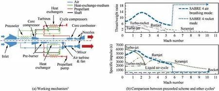
Fig. 1 Working mechanism and characteristics of precooled airbreathing propulsion.
The objective of this review is to provide a systematic overall review of the latest technology for the potential micromanufacturing processes that are applicable in the manufacturing process of compact high-temperature heat exchangers.In addition, the boundaries of micromanufacturing constraints are highlighted and can be used as a reference for the design of compact heat exchangers. Finally, the technical difficulties and future trends are discussed for the fabrication of compact heat exchangers for the hypersonic precooled combined cycle engine.
2. Categories of compact heat exchangers used in HPCCE
Synergetic cycle propulsion optimizes performance by transforming between the airbreathing mode(mainly including turbojet, turbofan, and ramjet) and the rocket mode during the flight period. For airbreathing, the imported airstream must be effectively cooled to enhance the thrust and the specific impulse to increase the flight scope and engine performance.Based on the cycle mechanisms, the typical hypersonic precooled cycle engines can be classified into single cycle engine,such as turbojet and turbofan, and combined cycle species,such as turbine-based combine cycle (TBCC) and HPCCE.Japan Aerospace Exploration Agency (JAXA) initiated the expander cycle air turbo ramjet (ATREX) project in 1986.ATREX can operate from take-off to Mach 6 at the altitude of 26 km continuously without mode transition.The precooler used in ATREX is a shell-and-tube heat exchanger composed of 1296 stainless steel tubes of 320 mm in length,2 mm in outer diameter, and 0.15 mm in wall thickness.12The design objective of the ATREX precooler was to realize 160 K air temperature and 0.95 pressure recovery.20To further and more effectively cool the air, the air collection and enrichment system(ACES)was proposed by adding an air separator that separates nitrogen and oxygen to obtain liquid oxygen for later use in rocket mode. The air-hydrogen precooler in ACES is characterized by a pressure resistance of 1.6 MPa on the cold side and a temperature resistance that ranges from 208 K to 480 K. The recommended precooler is a shell-and-tube aluminum heat exchanger that uses ferruled connections between the tubes and the endplates,and the microtubes feature an outside diameter of 3 mm and a wall thickness of 0.25 mm.21However, the air precooling permits a substantially higher compression ratio than that utilized in the ATREX cycle,especially if the overall cycle is fuel rich.Such a cycle was examined in Russia for a deeply cooled air turborocket engine(ATRDC).22ATRDC utilizes the precooler to add the fuel liquid hydrogen to realize deep cooling of the flow to reduce the temperature to the liquefaction point.23The key components include an inlet heat exchanger, a turbocompressor and a hydrogen heater,while the air precooler consists of several sections that are displaced along the axis for front area reduction.The air temperature upstream of the compressor is between 98 and 112 K. However, the air precooler is the bulkiest component of the ATRDC cycle,which accounts for 40%of the total engine weight(without the air inlet).24The main feature of the previously discussed cycles is precooling of the incoming air using the heat sink capability.However,the mass-injected precompression cooling (MIPCC) propulsion system features a conventional turbojet or a turbofan engine as the core propulsion unit with a specially designed fluid injection system that sprays water and/or liquid oxidizer into the engine inlet,which was proposed by the United States.To realize a range of Mach numbers, an MIPCC system was added to the conventional turbine engine to form the precooled TBCC system, which is also known as the MIPCC-TBCC engine.25
Compared with the above schemes, the precooling combined cycle engine termed SABRE proposed by REL in the United Kingdom represents a substantial technical innovation by introducing helium as the third fluid into the thermal cycle between the incoming airstream and the liquid hydrogen.SABRE has attracted widespread attention and a series of studies have been conducted.4,7,8,26–28Advanced compact heat exchangers play an important role in SABRE mainly as a precooler between the air and the medium, as a heat exchanger between the high-temperature gas and the heat-exchange medium,and as a hydrogen/helium heat exchanger.The most complicated heat exchanger is the precooler,which has a shell-andtube configuration. REL investigated the precooled engines,SABRE,and conducted a series of experiments about counterflow heat exchangers with small-bore thin tubes.29The precooler was applied to cool 172 kg/s of air at a recovered temperature of 1250 K to 665 K while incurring an airside pressure drop of 0.4 bar at Mach 5 cruise. This element represents a breakthrough for REL by exploiting heat exchangers that are 100 times lighter than existing exchangers, which can cool airstreams from over 1000°C to -150°C in no more than 0.01 s. In addition, Kim et al.30elaborated the manufacturing process of a precooler developed in Korea for installation into a real civil aircraft engine. In March 2019, it was reported that REL had successfully completed the hightemperature assessment of a full-size precooler prototype engine under Mach 3.3 condition. The high-temperature heat exchanger is placed downstream of the preburner to maintain the helium at a temperature of 1250 K by using the preburner exit flow during the engine operation.The temperatures of the preburner exit flow and the inlet helium stream are 1506 K and 669 K,respectively. To tolerate the ultrahigh temperature and realize satisfactory performance, REL developed a silicon carbide heat exchanger with a complex involute matrix spiral structure, in which the spiral length of the plates along the radial direction is 374 mm.7The heat exchanger is used to cool the helium to the desired temperature, which operates inside the closed Brayton cycle for SABRE. The temperature of the medium of the hydrogen/helium heat exchanger is between 30 K to 800 K.8The huge temperature difference requires high performance and restricted weight and size of heat transfer.REL intended to use the Print Circuit Heat Exchanger(PCHE)as a hydrogen/helium heat exchanger,which is highly anticipated and valued in the energy and aero-propulsion field.The PCHE includes diffusion-bonded plates with microchannels that were formed via the manufacturing processes of chemical etching, micromachining and microforming and can be applied with high effectiveness to a wide temperature–pressure range. The thermal soaking period during the diffusion bonding process realizes an interface-free join between the plates, which guarantees containment of the base-material strength and high pressure. The characteristics of the diverse compact heat exchangers that are used for HPCCE are outlined in Table 1.
Furthermore, an ideal material for compact heat exchangers in HPCCE should exhibit high mechanical strength and high temperature resistance and be of light weight. The lightweight alloys, which include titanium alloys, aluminum alloys and high-temperature-resistant materials,such as Inconel, silicon carbide,and refractory metal alloys,are chosen according to the operational conditions. However, the poor manufacturability of high-strength and high-temperature-resistant materials leads to increasing difficulty and cost of the manufacturing processes. For the heat exchangers used in HPCCE,the various manufacturing options, which include microforming, micromachining, power sintering, chemical etching,lithography, and additive manufacturing, are convenient to use. This paper highlights the manufacturing issues and the recent efforts in the development of microfabrication technologies for compact heat exchangers.
3. Manufacturing requirements of compact heat exchangers
As discussed,the unique demands of HPCCEs require the continuous promotion and development of fabrication techniques for compact heat exchangers. In the design of a heat exchanger, the manufacturing constraints of various processes must be considered. The requirements for the micromanufacturing of compact heat exchangers can be divided into two levels,namely, the passage level and the product level, and the cooling passage has the microfeatures, such as microchannels and microtubes. Compared with the manufacturing of macroscaled products, the technologies for the fabrication of compact heat exchangers may differ. Micromanufacturing technologies overcome the problems at microscale by scaling down or modifying the traditional methods. Furthermore,the manufacturing chains often differ substantially from the traditional ones, which is due to the unique characteristics at microscale such as material properties, structural strength and stiffness, clamping/releasing, size effect, residual stress and surface integrity.32For example, during the fabrication of PFHEs and PCHEs, distortions often occur, which are in the form of nonuniform fin spacing, recurved fin shape or an open fin. These nonuniformities are likely to reduce the pressure drop and the heat sink performance, which is unacceptable for the gas turbine and related applications. Therefore,the stability of the dimensional accuracy of compact heat exchangers used in HPCCEs must be strictly maintained. In addition, the microstructural properties and the mechanical integration of each passage in a compact heat exchanger should be simultaneously ensured due to the high pressure and temperature cycle.In addition,frost formation on the cold surface of the heat exchanger is an undesirable phenomenon,which heavily impacts the heat transfer performance. Therefore, many frost-formation countermeasures have been pro-posed. Since the defrost processes are prone to being influenced by the surface wetting characteristics, functional surfaces or coatings that have the superhydrophobic property have been designed for defrosting.33In this scenario, it is necessary to consider the fabrication of functional microstructures prior to manufacturing the microchannels or microtubes to realize the integrated structure. Moreover, coolant channels and plates must be assembled and joined to satisfy important requirements,such as sufficient hermeticity,high strength,free circulation throughout the entire passage, and resistance to corrosion by the high temperature.Meanwhile,the fabrication process is capable of batch production for improving the manufacturing efficiency and reducing the cost. Many traditional and innovative techniques have been used to fabricate compact heat exchangers. Typical micromanufacturing processes, such as microforming,micromachining,sintering,chemical etching,LIGA, additive manufacturing, and microjoining, are described in detail in the next section. The manufacturing requirements of compact heat exchangers that are specified above are presented in Fig. 2.
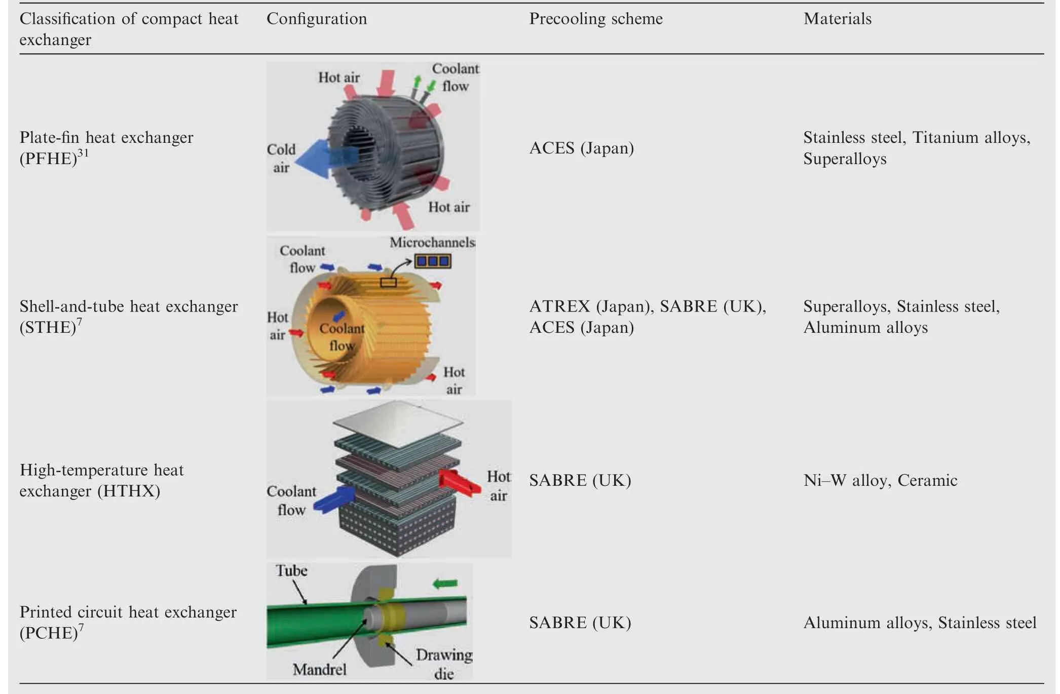
Table 1 Summary of forms of compact heat exchangers used in HPCCE.
4. Potential micromanufacturing technologies of compact heat exchangers
The materials of heat exchangers for HPCCEs are subjected to high temperatures and, therefore, encounter many problems and challenges, such as creep, strength reduction, oxidation,corrosion, and thermal shock. Most conventional heat exchangers designed for low-temperature applications are no longer economical or practical at high operating temperatures.Materials that are used at lower temperatures, which include steel, copper, and aluminum, often lose their thermomechanical properties at high temperatures. Therefore, they are inapplicable in the hypersonic aeroengine. Hence, alloys that can maintain their strength even at high temperatures are the ideal materials. However, the thermal conductivity and manufacturability are always unsatisfactory.31According to the characteristics of the compact heat exchanger that is used in HPCCEs, the potential micromanufacturing processes can be classified into forming, subtractive, additive, hybrid and joining,17as listed in Fig. 3.
4.1. Microforming processes
Microproducts can be fabricated via forming methods,namely, microforming technologies, which offer attractive characteristics, such as higher productivity, higher material integrity, less waste, and lower manufacturing costs.34However,considering the increasing difficulty of fabricating microtools with high accuracy, scaling down the conventional process to the microscale is not simple. In addition, due to the size effect with miniaturization, the increase in frictional resistance between the tooling and the workpiece will cause a decrease in the forming limit. Microforming is suitable for manufacturing the microtubes in STHE and the microchannels in PFHE and PCHE.A variety of methods,such as microtube drawing, microstamping, microembossing, microhydroforming, microextrusion and microrolling, which are suitable for prototyping, low-volume production, or high-volume production of compact heat sinks are reviewed.
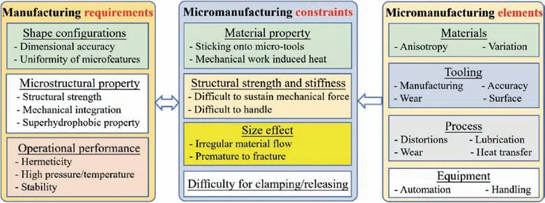
Fig. 2 Key issues in fabrication of compact heat exchangers for HPCCEs.

Fig. 3 Classification of potential micromanufacturing technologies for compact heat exchangers in HPCCE.
4.1.1. Microtube drawing
In the above brief review,the promising potential of STHEs in HPCCEs is discussed. However, their large-scale applications are closely associated with the development of a feasible,viable and reliable manufacturing process and tooling. The development of application-oriented fabrication technology of hightemperature-alloy microtubular components is limited. In addition, the materials used in STHEs for HPCCE include Inconel and titanium alloys, which exhibit poor formability at room temperature. It is highly difficult to fabricate such alloys into microfine tubes via cold forming processes.
Currently, only a few institutions, including REL in the UK, Beihang University in China and Korea Maritime and Ocean University,have conducted R&D trials on the manufacturing process development of Inconel microtubes. REL used tube drawing technology to produce 1-mm-diameter tubes with a wall thickness of down to 30 μm in Inconel 718.7Beihang University also investigated the manufacturing of microtube heat exchangers for HPCCE.35,36Inconel 718 microtubes with an outer diameter of 0.9 mm and a wall thickness of 55 μm and Nb-W-Mo-alloy tubes with an outer diameter of 2.0 mm and a wall thickness of 100 μm were fabricated, as shown in Fig. 4. The Inconel 718 tubes can withstand a pressure of 100 bar at 875 K, while the niobium-alloy tubes can bear 400 bar before rupturing at 1675 K.Kim et al.30in South Korea explored the manufacturing process of fine tubes and formed tubes with Inconel 625 strip of 0.15-mm thickness via tungsten inert gas (TIG) welding followed by multipass drawing processes. Five annealing processes were necessary to obtain tubes with a 1.5 mm outer diameter and 0.12 mm thickness.
All the reported efforts on manufacturing Inconel fine microtubes are based on the conventional forming technologies,namely, multistep tube milling with multipass cold drawing, as illustrated in Fig. 5. The process route consists of (1)hot working a cast feedstock to obtain a solid billet, (2) deep drilling a hole in the billet to obtain a tube, (3) multipass cold drawing with a fixed or moving mandrel to reduce the diameter and the wall thickness,and(4)multistage sink drawing to further reduce the outer dimension to the target diameter. To regain the plastic property of the Inconel alloy, an annealing process was conducted after every-two or three drawing steps.To reduce the number of drawing steps the hot working process is usually performed via extrusion with a mandrel and a tubular billet,whereas the tube drawing is conducted at an elevated temperature. Multipass hot extrusion is applied to produce a hollow billet, while multistage tube drawing with intermediate annealing is subsequently applied to stretch the hollow billet. However, scaling down the first process for the smaller-sized tube is not easy due to the difficulty of accurately fabricating the microtool and inserting a plug or a mandrel into a microtube.
To overcome these issues, the second processing route is proposed,namely,dieless hot drawing technology,for the fabrication of microtubes without tools, such as a die, plug or mandrel.37–40In contrast with die drawing, dieless drawing uses no tool or die, yields a larger reduction in area, and is a more flexible process. This deformation process realizes the economy of materials in a single pass via the local heating and cooling. However, there remain substantial problems in the dieless drawing process of microtubes. In this process,the surface smoothing mechanism that results from sliding between the tube and tooling is unpredictable, and the roughening phenomenon on the free surface is unavoidable.Furthermore, the heat transfer behavior is closely related to the deformation behavior in dieless drawing. Time is required to increase the temperature of the tube,and it is difficult to draw the tube at high speed. In addition, the current materials used in dieless drawing are zinc alloys,stainless steel and aluminum alloys,and the processing of high-temperature alloys has yet to be extensively explored. Table 2 summarizes the advantages and disadvantages of the two processing technologies for fabrication of microtubes.
According to the above discussion,the dimension accuracy,microstructural evaluation, surface finish, mechanical performance, and the yield of the fabricated microtubes can be controlled by current microtube drawing process for Inconel alloy.However, it is tedious and inefficient to fabricate a microtube with diameter of less than 1 mm because the decreased forming limit at microscale. Furthermore, these processes may lead to uncontrollable wall thickness distribution, complications in the facility, and the imperfect microstructure if an inappropriate route is applied.Therefore,a hybrid process that combines the various energy fields is urgently needed to improve the forming quality and reduce the manufacturing difficulties.
4.1.2. Microstamping

Fig. 4 Microtubes produced by authors.
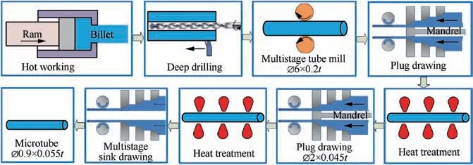
Fig. 5 Microforming process for manufacturing Inconel seamless microtubes.
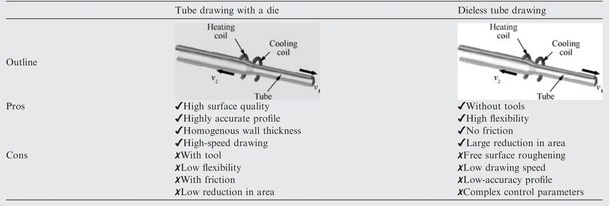
Table 2 Advantages and disadvantages of two processing technologies.
Considering the requirements of microchannel arrays in PFHE in terms of accuracy,productivity and reliability,microstamping is considered to be a satisfactory option. Precise dies with micromachined channels are used to deform thin sheets via stamping, as illustrated in Fig. 6. A substantial amount of research has been conducted on increasing the forming quality of microchannel cells for the applications of fuel cell metallic bipolar plates and microturbine primary surface recuperators.Jin et al.41formed channels in a 0.1-mm-thick SS304 plate via a microstamping process in which the upper die was lowered to press the blank between the upper and lower dies.Peng et al.42surveyed the recent progress on microstamping processes for stainless steel bipolar plates. Treece et al.43reported the microstamping process of a fin fold stock, which is used for recuperated microturbines. Kesseli et al.44developed a highvolume progressive stamping process for efficiently fabricating microchannels on sheet metal,which can produce hundreds of finished products per hour. However, current investigations focus on low-strength or high-ductility materials, such as aluminum alloys and stainless steel, and the feasibility of microstamping for processing titanium and Inconel alloys remains to be investigated in both theory and practice.It is seen from Fig.6 that hundreds of microchannels can be formed on the metal foil simultaneously. Therefore, the primary characteristic of microstamping process is high efficiency. The production cost is relatively low, which is mainly concentrated on the manufacturing process of precise dies.However, the microchannel dies are difficult and expensive to manufacture, and the requirement for positioning is strict.In addition, the surface quality of the stamped specimens is able to remain the original sheet due to the restrictions of two-sided patterns.
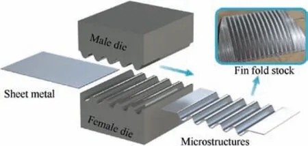
Fig. 6 Microstamping process and fabricated fin fold stock.43
4.1.3. Microembossing
The microembossing process is a forming method commonly used to fabricate micro- and nanostructures on sheet metal.Unlike the microstamping method,the microembossing is conducted by one die with micro-channels. The materials are squeezed into the micro-channels to form the target shape via the localized plastic deformation. Therefore, the surface quality of embossed micropart is inferior compared with that produced by microstamping method. According to Namoco et al.,45the mechanical properties can be improved via the embossing process, and the tensile strength, bending strength,elongation, and rigidity of aluminum alloy sheets were increased in their research.Gu¨ler et al.46embossed bulges with various heights onto Al 1050 plain sheets of thicknesses of 0.4,0.5 and 0.8 mm,thereby leading to increases in the yield,bending and buckling strength but a decrease in the tensile load.
The embossing process can produce raised or sunken structures with various designs. Sang et al.47formed high-fidelity nanosized protrusion patterns on aluminum plates successfully via a direct embossing process and demonstrated that the forming quality could be further improved by increasing the pressure or softening the material. Zahner et al.48fabricated cuboid geometries with a width of 50 μm and a height over 30 μm,and the dimensions were smaller compared to the structure on the punch due to the springback phenomenon. Su et al.49created microchannel arrays on LZ91 Mg-Li alloys via the microembossing process, as shown in Fig. 7. Microarray channels with widths that ranged from 50 to 200 μm were formed under a load of 2 kN and a temperature of 423 K,and the embossing quality was substantially affected by the grain size as the ultrafine-grained material showed better geometrical transferability and fewer defects than the coarse-grained material.
For manufacturing microchannels on stainless steel plate,hot embossing and laser shock embossing were proposed. Fu et al.50explored the manufacturing process of a micro-scaled cylindrical array with a height of 200 μm and an aspect ratio of 2 on 316L stainless steel via the hot embossing method,where the microcavity on the mold was more completely filled with increasing pressure and temperature. Liu et al.51conducted laser shock embossing tests on metallic foil and proposed a simulation model, which was validated by the successful compression of the microchannel pattern by a single pulse. It is found that the microembossing process is suitable for the fabrication of low-strength materials and shallow microchannels due to the large deformation load.
4.1.4. Microhydroforming
Hydroforming is a deformation-based manufacturing technology that uses pressurized liquid as the medium to produce ideal part shapes from tubular stocks or sheet metals.As illustrated in Fig.8(a),the sheets are placed between two dies and form an enclosed cavity. Then, the high-pressure medium is filled into the cavity to produce the final configurations based on various fluid pressures. It is necessary to optimize the microhydroforming process to obtain high-quality products and to enhance the reliability of the process. The microhydroforming process has been widely applied to produce the bipolar plates for proton-exchange membrane fuel cells,42however, the production of compact heat exchangers via microhydroforming is seldom reported. Piper et al.52optimized the parameters of a complex wavy channel that was created via a microhydroforming process to produce a pillow-plate heat exchanger (PPHE),as shown in Fig. 8(b). Mahabunphachai and Koc¸53developed a hydroforming apparatus for conducting microchannel hydroforming experiments on thin SS304 sheets with 51 μm thickness and various grain sizes from 9.3 to 17.0 μm,and they discovered that the small variations of the in-plate and between-plate channel dimensions are below 5 and 20 μm,respectively.
The advantages of microhydroforming include good flexibility, ability to form complicated shape, and high efficiency,42,54which is similar to macro hydroforming process.In addition, microhydroforming has its unique applications due to its superior characteristic of high precision and less springback.However,the microhydroforming process is heavily depended on the complicated and specialized equipment.
4.1.5. Microextrusion
Microextrusion is a forming method for processing microparts with a designated cross-section shape via the plastic deformation of materials,as illustrated in Fig.9.The extrusion method is mostly used to create straight-channel heat sinks,structured tubes and micropins.55However, the precision of the die and tools strongly affects the quality of the extruded workpiece,and further research and development are necessary for the mass application of microextrusion.
The forming quality of the microextrusion process is mainly affected by the material category of the billet,the dimensional accuracy of the die,the processing parameters,and the lubrication conditions. Kamitani et al.56formed microgroove arrays on the surface of aluminum plane plates using cold extrusion experiments, where they found that the surface roughness was strongly influenced by the deformation zone and the lubricant.Tang et al.57obtained a novel device composed of microgrooves, primary fins, and compound fins via a plowingextrusion process and investigated the plastic deformation and fracture characteristics of the metal.Jian et al.58fabricated microgrooved channels with a reentrant cavity array for heat transfer enhancement via a similar method. Wang et al.59,60introduced the microextrusion technology into the pipe drawing process, where a type of pipe with leading and secondary microgrooves was formed and the heat transfer performance was improved. In addition, the deformation behavior of the material is gradually dominated by the size effect as the characteristic dimension of the workpiece decreases to microscale.Parasiz et al.61demonstrated that micropins with an extruded diameter of 0.57 mm exhibit a curving tendency as the grain size is increased to 211 μm, and this phenomenon was not observed when the grain was finer.
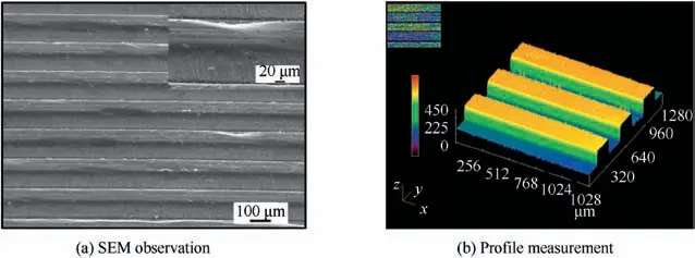
Fig. 7 Examination of the surface morphology of the microchannels.49
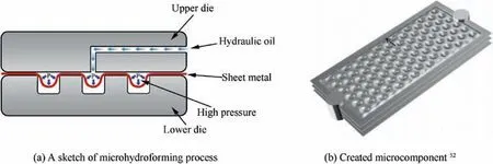
Fig. 8 Microhydroforming process and its fabricated microchannels.
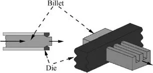
Fig. 9 Schematic diagram of microextrusion process.55
Microextrusion has an advantage of forming dense structure. The inner grains are refined through the process. However, the lubrication conditions of microextrusion is more difficult to control comparing to macro extrusion process, as well as the processing parameters.
4.1.6. Microrolling
To realize lower material thinning and higher aspect ratio of microparts, the microrolling process was established, in which a flat metal sheet is formed into desired shapes progressively and continuously by passing through the rollers.62Hirt et al.63manufactured large-area riblet structures on Al99.5 sheets with initial thicknesses of 1, 1.5 and 2 mm. The rolls used in their study were winded by steel wires with various diameters, and the tiny sharp-ribbed structures could be produced during microrolling, as illustrated in Fig. 10. Furthermore, Huang et al.64used involute gears as rollers to fabricate microchannels with an aspect ratio of up to 1.0 and a thickness reduction of less than 18.7%on the 0.1 mm thick SS316L sheets.Xu et al.65produced microchannel arrays on AA5052-H32 sheets via single- or double-pass microrolling strategies, with depths and widths of approximately 20 and 30 μm, respectively. Shimoyama et al.66discussed the deformation characteristic and microstructural evolution of the AZ31 magnesium alloy during the application of a novel microrolling method, namely, periodical straining rolling. The strong texture of the material is weakened, and the defects on the grooved surface are eliminated.
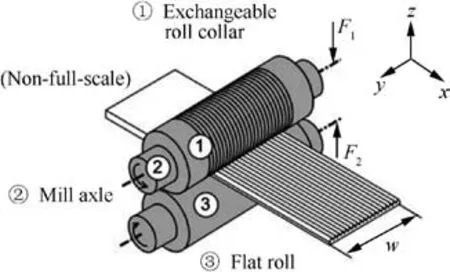
Fig. 10 Microrolling setup with surface microstructures.63
The theoretical model and numerical simulation of the microrolling process for structured sheet metals have also been widely investigated. Hu et al.67investigated the roll-to-roll forming method for obtaining microgrooves on a 6061 aluminum alloy sheet. A constitutive model was developed and the influences of process parameters were analyzed experimentally and via the finite element (FE) method. Clocke et al.68conducted a feasibility study on fabricating small riblet structures with a size of a few hundred microns. The experimental and FE simulation results demonstrated the advantages of this process including direct structuring, increased hardness, positive grain flow, and compressive residual stresses. Bui et al.69described a quasi-static model of the microrolling process,and the deformation behavior of the material was successfully predicted.
The forming quality of microrolling is also influenced by the grain size. According to Gao et al.,70the rolling force is decreased with increasing grain size in the roll-to-plate imprinting process, while the surface roughness and profile irregularity are aggravated by increases in the grain size, the groove width, and the rolling depth. Kim et al.71proposed a numerical scheme for simulating the intergranular microstrip rolling process via the FE method, in which the influences of the grain size and the grain boundary were considered. Therefore, microrolling has the advantages of low cost, desirable microstructural property and high production rate, and it is thus suitable for the fabrication of low-strength microchannels for PCHEs.
4.2. Microscaled subtractive processes
Although the microforming process is usually used to achieve fine microtubes and sheets with microstructures, it is not suitable for the fabrication of the holes or ditches with super large ratio of depth to width,difficult-to-deform billets and the complicated microchannels. Therefore, microscaled subtractive processes including micromechanical cutting, laser-beam micromachining, and micro-electrical discharge machining(EDM) are widely adopted.
4.2.1. Micromechanical cutting
Micromachining is a removal process of ultraprecision material, which can realize micro-shapes with an accuracy of a few nanometers.Although there are many similarities to traditional machining, micromachining remains a huge challenge due to the size effects.72Recently, complicated and troublesome challenges in precision machining for micromachining in terms of predictability, productivity and producibility were gradually resolved. Many studies have focused on microscale surface patterning and machining of difficult-to-cut materials,which mainly include metal matrix composites,silicon carbide,and the Inconel alloy.
1) Micromilling
Pan et al.73,74proposed a new multicutter milling technology for machining multiple parallel microchannels simultaneously using a composite cutting tool that is integrated with several slotting cutters. The thicknesses of slotting cutters range from 50 μm to 500 μm, which provides possibilities for machining high-aspect-ratio microchannels in PCHEs, as exhibited in Fig. 11(a). One plate is immobilized by four fixed bolts on the mounted plate, which is immobilized by a vise.Based on the x-and y-directions of the worktable,by combining the rotation and the movement along the z-direction of the slotting cutters,the machining process produces microchannels in three directions. The composite cutting tool provides the possibility of machining a substantial number of microchannels. Fig. 11(b) depicts the milling tool that is integrated with five slotting cutters, along with a handle, a locking gasket, a pinch nut, and four gaskets. The slotting cutters and gaskets are stacked alternately together and fixed by a lock gasket and a locknut, which facilitates dismantling and replacement.The multicutter milling substantially shortens the processing time and the workpiece removal rate is eight and fifty times larger than those of EDM milling and reactive ion etching,respectively. High-quality microchannels with a width of 240 μm and a depth of 1000 μm were produced on a red copper plate via the multicutter milling method, as shown in Fig. 11(c). Recently, Zhou et al.75exploited a combination tool with stacked blades and manufactured microchannel plates with high efficiency.
In addition to multislot milling,microend milling is used to create microchannels for compact heat sinks and is a feasible option for prototyping and small-scale production. Jasperson et al.55,76investigated the possibility of using micro pin–fin heat sinks as an alternative to microchannel heat sinks and summarized the manufacturing approaches of the two heat exchangers. Furthermore, they manufactured micro-PFHE on copper using microend milling, in which the dimension of the cutting tools was between 5 and 1000 μm in diameter, to produce microscale features on micro, meso-, and macroscale parts, as illustrated in Fig. 12(a). The produced pin width and gap are consistent, namely, with a distance of 200 μm between the heat sinks, as shown in Fig. 12(b). However, the cost of microend milling a micro pin–fin heat sink is approximately-three times larger than that for a microchannel heat exchanger. Therefore, the microend-milling method is ideal for prototyping. Va´zquez et al.77explored the characterization of the micromilling process for manufacturing microchannels on aluminum and copper with hardnesses of 21 and 72 HRB, respectively. They created microchannels of 200 μm in width and 50 or 100 μm in depth and found that the machining quality of microchannels in aluminum is superior to that in copper. In addition, they investigated the effect of optimal selection of the micromilling parameters on the microchannel feature precision and surface roughness via particle swarm optimization.The materials that were measured in their research were an aluminum alloy (AL-7075) and a titanium (Ti6Al4V) alloy with hardness values of 21 HRB and 107 HRB, respectively.78Monroy-Va´zquez et al.79evaluated the dimensions and geometries of burrs and the surface roughness of aluminum,steel AISI 316L,and Ti6Al4V in the micromilling process.They discovered that the coolant influences the quality of superficial features and effectively eliminates the overheating and edge stacking. In addition, Friedrich and Kang80manufactured a heat exchanger with channels that were 100 μm wide by 80 μm deep on 127 μm-thick copper foil.Their device exhibited a volumetric heat transfer coefficient of nearly 45 MW/m3·K under very conservative design and operating conditions. Park et al.81explored the impacts of various cooling/lubricating approaches on the processing of the Ti6Al4V alloy and concluded that it is beneficial for the tool life to integrate a minimal amount of lubrication with internal cryogenic cooling, which can prolong the tool life by 32%.
2) Microturning
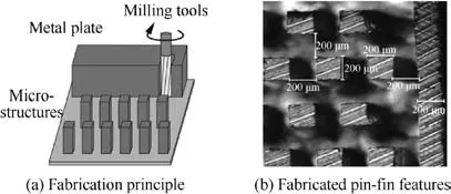
Fig. 12 Microend-milling process.55

Fig. 11 Multicutter milling process.74
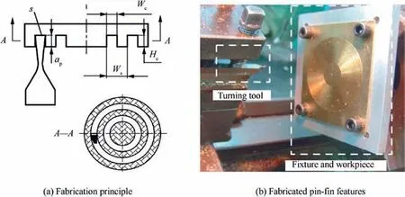
Fig. 13 Microturning process.82
Tand et al.82fabricated ring-shaped microchannels via the microturning process, as illustrated in Fig. 13(a) and demonstrated that the microchannel depth is equivalent to the cutting depth and that the width depends on the length of the major cutting edge of the tool. Superhard high-speed steel W9Mo3Cr4V3N and brass CuZn37 were selected as the tool and workpiece materials, respectively. The width and depth of the ring-shaped microchannel are both 0.8 mm.
The main materials used in micromechanical cutting are copper, aluminum, and steel, which have been gradually replaced by new types of materials, such as titanium alloys and nickel alloys, whose properties can be maintained even under extreme operating conditions. However, it is not easy to mill these alloys for multiple reasons. Therefore, the machining processes can only be conducted at very small rates.Lo´pez de lacalle et al.83performed multiple machining experiments on the Ti6Al4V alloy and the nickel-based 718 alloy,which are commonly used in the aeronautical industry. They found that both types of alloys exhibit crucial problems in terms of the machinability of the material; these issues are induced by the low thermal conductivity and the reactivity with the hard metal of the titanium alloy.For the nickel alloy,the problems are due to the small thermal conductivity and volume specific heat. To address these issues, the influences of various tool materials on the machinability have been investigated,such as aluminum oxide base cermet,a special coating of carbide and whisker-reinforced ceramic84. Courbon et al.85assessed the application of high-pressure jet assistance(HPJA)in the rough turning of Inconel 718 with coated carbide tools,and the tests were performed via a longitudinal turning process on a conventional lathe, which was fitted with a high-pressure plunger pump with a pressure of 150 MPa.HPJA outperforms traditional lubrication,especially in terms of chip breakability,decrease of the cutting force and the thermal loads that are imposed on the tool.
4.2.2. Laser-beam micromachining
In the past ten years, laser technology has been increasingly applied in the manufacturing of microproducts in material processing. The characteristics and parameters of the laser occupy a crucial position in micromachining,such as the wavelength,average power,intensity,fluence,pulse duration,pulse repetition rates, and peak power. In a laser-beam machining process, an intensely focused and coherent stream of light vaporizes or chemically ablates materials at high peak power within a short interaction time and generates a small heataffected zone and a recast layer on the surface. With the advantages of high lateral resolution, high flexibility, and low heat input, laser technology is recognized as a microtechnology that can fabricate various non-silicon materials with high efficiency. For laser-beam-assisted micromachining for compact heat exchangers, Zhou et al.86introduced the laser micromilling technique into the fabrication process of microchannels in pure copper material. One-hundrednanosecond pulses with a wavelength of 1064 nm at a repetition rate of 20 kHz were applied, and adjustable laser output power enabled the manufacture of microchannels of various dimensions, as illustrated in Fig. 14(a). The finished microchannels are presented in Fig. 14(b), and the minimum width is 100 μm. They demonstrated that the error compensation design should be applied in the laser micromilling process for various microchannels to reduce the error of the machined width. Moreover, Deng et al.87produced micropin fins for PFHE via multiple-pass laser reciprocating scanning. In the laser micromilling process of pure red copper plates,a focused,high-energy–density spot area is created,and the heated material is removed after melting, evaporation, and ionization.88
In laser-beam micromachining, the effects of the laser parameters on the machining performance have been explored.Ahmed et al.89investigated microchannel fabrication in Inconel 718 via Nd:YAG laser-beam machining. They identified a suitable combination of parameters that can yield superior results for a channel size of 100 μm×100 μm: a laser intensity of 92.7%,a repetition rate of 30 kHz,and a scanning speed of 300 mm/s.However,when the channel size is reduced to 50 μm×50 μm, the bottom width is completely absent and the top width and depth deviate from the designed values.Furthermore, they compared the laser-beam machining of IN 718 channel profiles under dry and wet mediums.90They found that laser-beam micromachining under distilled water is more productive than that under an air environment because the water conditions can generate two microchannels, while the dry conditions can generate only one.
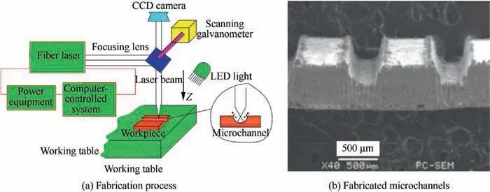
Fig. 14 Laser micromilling technique.86
Various factors influence the processing properties and the quality of microfeatures. Alahmari et al.91optimized the laser parameters of Nd in a titanium alloy(Ti6Al4V),an aluminum alloy (AA 2024), and a nickel-based superalloy (Inconel 718)via a response surface methodology (RSM)-based full factor experiment. For the Ti6Al4V alloy, the ideal parameters of Nd are 83.57% lamp current intensity, 30-kHz pulse frequency, and 400 mm/s scanning speed for generating microchannels of size 100 μm.For the AA 2024 alloy,the optimal values of these three parameters are 83%, 30 kHz, and 300 mm/s, while the optimal values for the Inconel 718 alloy are 82%, 37 kHz, and 300 mm/s, respectively. In addition,Teixidor et al.92explored how the parameters of laser milling process affect the final geometry and surface quality of microchannel features that are fabricated on AISI H13 steel.They argued that the multicriteria ranking and parameter selection method is a feasible approach for identifying the optimal combination under the specified quality scope.
According to the above literatures,the microscaled subtractive processes have the advantages of ultra-high product precision and ultra-high surface quality. However, the tool life is still a key issue in micromachining process, and the material utilization and fabricating cost are also obstacles with regard to technology development.
4.2.3. Micro EDM
Over the past decades, miniaturization has been a trend in the development of machined components and has resulted in increasing requirements for microfeatures. Micro EDM has a similar physical mechanism to spark erosion, however, it is not an improvement to the micron level.There are remarkable differences in many aspects, such as the tool size, the fabrication method, the gap control and the machining technique.Several examples of heat sinks have been created via micro EDM technology. Coursey et al.93produced heat sinks with a channel width of 0.36 mm, a fin width of 0.50 mm, and lengths of 0.25 mm, 0.50 mm, 1.0 mm, 3.0 mm, and 5.0 mm via EDM. Lu et al.94created microchannel arrays with an active area of 41 mm×25 mm via micro EDM on the surface of a copper alloy sheet. The minimum channel width and height are 183 and 609 μm, respectively. Clijsters et al.95proposed a die-sinking EDM technique for manufacturing components in commercially available Silicon-infiltrated Silicon Carbide (SiSiC), which has been widely applied in heat exchangers. They explored the influences of electrical parameters, such as the discharge current, on the machining performance and fabricate microchannels with a width of 1.0 mm and a depth of 2.5 mm, as depicted in Fig. 15.
Micro EDM is regarded as an indispensable method due to its noncontact machining capability. Despite its suitability,micro EDM has several shortcomings.For example,it exhibits a necking phenomenon at the end of the drilling operation and produces defects in the tungsten rods due to residual stresses.In addition, it is time consuming in large-scale production,which limits its application in the fabrication of compact heat exchangers.
4.2.4. Photochemical machining
Photochemical machining (PCM) removes material by controlling the dissolution process under the action of strong chemical etchants.96This corrosive oxidation of the material has no effect on the internal structure and characteristics.The process of fabricating microchannels via PCM is illustrated in Fig. 16, which consists of eight main steps. First,all specimens were cleaned to wipe off specks of dirt thoroughly prior to the application of the photoresist coating and were treated with dry air. Subsequently, the specimens were coated with liquid-film photoresist at various spinning speeds.Since the soft baking increases the photoresist adhesion to the substrate surface, it was conducted to eliminate residuary solvent from the photoresist membrane and to increase its adhesion. After that, ultrasonic vibration (UV) exposure was performed and the postexposure baking was utilized to eliminate the standing-wave effect. The photoresist films were developed in sodium hydroxide solution, and discs with patterned photoresist films were immersed and etched by hand stirring the mixture solution. Finally, the residual photoresist films and the reaction products in the textures were removed and cleaned with acetone.97
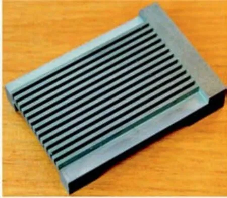
Fig. 15 Machined microchannels via EDM.95
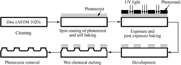
Fig. 16 Process of microchannel fabrication via PCM.97
Numerous studies have been conducted in this field.Nageswara Rao et al.98explored the influence of various acids in FeCl3solution on the etching speed of stainless steel under various temperatures. They identified the optimal conditions under a channel depth of 180 μm and an etch factor of 1.36 after 160 min of etching. Mylavarapu et al.99,100investigated the photochemical etching performance of Alloy 617 plates,and plate patterns with approximately semicircular shape and a channel width of 2 mm were created,as shown in Fig.17.In addition,Chu et al.101produced a plate of PCHE with straight ribs via the photochemical process.The thickness of the plate,the width of the rib,and the overall length and width were 2.2,1.2, 150 mm and 100 mm, respectively. Patil et al.102,103explored the effects of the rolling direction, exposure time,temperature, and concentration on the forming quality of microchannels on Monel 400, and microchannels with undercuts of 250, 200, 150, 100, and 60 μm in width were created.
Due to the characteristic of high precision, PCM is an efficient way to convert metal into complex microchannels. However, the operation is tedious because the corresponding equipment and operation specifications are complicated.
4.3. Microscaled additive manufacturing processes
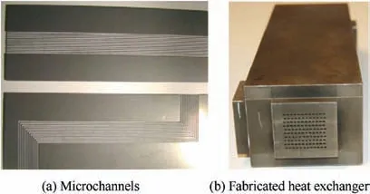
Fig. 17 Photochemically machined microchannels and a heat reactor.99
Although microforming and microscaled subtractive processes are typical approaches for fabricating structured surfaces,fabricating microchannels directly in bulk metals tends to be more profitable from a practical perspective, which is mainly applicable for ultrahigh temperature materials. Therefore, the microscaled additive manufacturing processes, including sintering, microinjection molding and microcasting, threedimensional printing, were applied to integrated manufacturing of hollow microparts.
4.3.1. Sintering
Due to the ultrahigh temperature during hypersonic flight,the ceramic microstructured heat exchanger was adopted, for which polymer or metal components are not suitable. However,the ceramic exchanger suffers from high fabrication cost.Only a few attempts have been made to manufacture monolithic heat sink from ceramics and silicon carbide. Lin et al.104fabricated microchanneled hydroxyapatite components via free pressureless spark plasma sintering (SPS), as illustrated in Fig. 18(a). The maximum sintering temperature was 1300°C. Alm et al.105sintered a green body into microchannels with Al2O3, which contained channels that were 250 mm wide, 500 mm tall, and 12.25 mm in length. After sintering,the microchannels exhibited a density of 98%and a linear sintering shrinkage of 11%-12%. Singh et al.106experimentally explored the use of sintered porous heat sink for the cooling of high-powered compact microprocessors. Meng et al.107created an alumina microchannel part via pressureless SPS, and each microchannel had a width of 200 μm, a depth of 135 μm,and a length of 4 mm,as illustrated in Fig.18(b).Furthermore, Ohmi et al.108presented a free-form microchanneling method for fabricating metallic microchannel components according to the microscopic infiltration mechanism. During the process, the body metal represents the structural material while the sacrificial core corresponds to the material that shapes the microchannel. The sacrificial core was composed of a mixture of an organic binder and a powder metal with a lower melting temperature than the body metal.Then, the body-metal powder compact with a shaped sacrificial core was sintered at a temperature that was between the melting points of the body metal and the sacrificial-core metal.They found that the addition of copper to the sacrificial-core metal alters the composition, structure and smoothness of the microchannel lining. In addition, Schulte-Fischedick et al.109described a sintered silicon carbide offset strip fin heat exchanger that was coated with a 100 μm cordierite environmental barrier coating. The construction includes 127 flue gas plates and 128 process plates that are sintered together to produce a counterflow heat exchanger block of dimensions 2 m×2 m×0.5 m with a fin spacing of 11 mm.
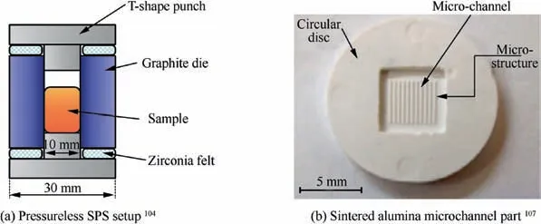
Fig. 18 Sintering process for microchannels.
In addition, Webber et al.8produced a silicon carbide,pure-alpha-phase and fine-grained silicon carbide product with almost no porosity. The manufactured tubes have an outer diameter of 2.0 mm and a wall thickness of as low as 0.35 mm, which can withstand a pressure of 700 bar without failure, as shown in Fig. 19.
4.3.2. Microinjection molding and microcasting
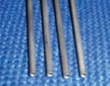
Fig. 19 Sintered silicon carbide tubes.8
Casting, throwing,injection molding,and dry pressing are the typical methods for the manufacture of ceramic heat transfer surfaces.The micropowder injection molding technique,which is suitable for the mass production of microparts,has received extensive attention and has undergone substantial development. The technique enables the reproduction of tiny features that are on the same order of magnitude as the powder size.Among several applications, the micro-heat exchanger is considered vital for microinjection molding. Federzoni et al.110developed an innovative processing route for manufacturing a plate-and-frame heat exchanger out of alumina with a channel size of 0.5 mm×0.5 mm that is based on the injection molding process,as illustrated in Fig.20.The main shortcoming of microinjection molding is that the original powder must be homogeneous with a diameter that is approximately-one order of magnitude smaller than the smallest targeted feature,which will increase the material cost. The process of casting is often used to create compact heat exchangers,to conclude the pouring of molten metal, and for solidification, to remove the workpiece in three steps. Kawahara et al.111produced an aluminum alloy fin stock for automobile heat exchangers via the twin-roll continuous casting method. The control of the tiny separation among micro-pins is the most difficult aspect of microcasting, which requires additional time and cost.112Therefore, the microinjection molding and microcasting processes are seldom adopted in the HPCCE sector due to the limitations on the microstructural performance and on the hightemperature strength of produced structures.
4.3.3. Three-dimensional printing

Fig. 20 Flow chart of the fabrication of heat exchanger.110
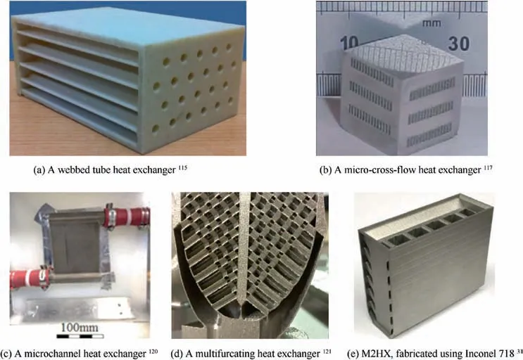
Fig. 21 Heat exchangers fabricated via 3D printing.
The weight reduction requirements of aerospace parts motivate the development of three-dimensional printing technology and accelerate the application of additive manufacturing in aerospace heat exchangers. Three-dimensional (3D) printing technology includes three main metal-based techniques: selective laser melting (SLM), direct metal laser sintering (DMLS),and electron beam melting(EBM).The SLM approach utilizes a special heat transfer mode and enables the production of the complicated structures and components of a heat exchanger.The high demands on the heat transfer rates, pressure drops and compact systems increase the design complexity of exchangers; however, 3D printing is highly conducive to the manufacture of heat exchangers.Previous studies have yielded results on the application of 3D printing techniques to the manufacture of complicated structures in heat exchangers.Romei et al.113analyzed the manufacturing process of a novel high-temperature spacecraft resistojet heat exchanger via SLM. They demonstrated that the fabrication of tiny feature sizes below 200 μm in 316L stainless steel via SLM is feasible.In a study by Thompson et al.,114the compact flat-plate oscillating heat pipe (FP-OHP) with dimensions of 5.08 cm×3.81 cm×1.58 cm was fabricated via SLM technology, which includes a Ti6Al4V casing and a circular minichannel of 1.53 mm in diameter that consists of four interconnected layers. In a study by Cevallos, a webbed tube heat exchanger was manufactured with polycarbonate via fused deposition modeling, as shown in Fig. 21(a). The inner and outer diameters of the tube are 5.0 mm and 9.0 mm, respectively, and the length is 120 mm.115Another work by Wong et al. succeeded in fabricating a complicated aluminum 6061 heat sink via SLM.116In addition, Tsopanos et al.117fabricated a micro-cross-flow heat exchanger via SLM. The minimum channel width is 300 μm, the height is 400 μm, and the fin width is 150 μm,as shown in Fig.21(b).Moreover,DMLS has realized the fabrication of metallic fins with a thickness of 150 μm. By using manifold-microchannel design and DMLS,Arie et al.118successfully fabricated a high-performance titanium alloy (Ti64) air–water heat exchanger and evaluated its performance experimentally.In addition,to realize the optimal performance and to maximize the heat transfer coefficient, a multiobjective optimization method is used. The results demonstrated that the additive manufacturing was able to enhance the performance based on complicated structures of the fins and manifolds.119Bacellar et al.120demonstrated that the optimal design can realize over 50% decreases in the size,materials, and pressure drop compared with the baseline microchannel. They also verified the optimization approach using a metal 3D-printed prototype of the heat exchanger, as displayed in Fig. 21(c). Gerstler and Erno121successfully produced a multifurcating heat exchanger via SLM for fuel-cooled oil cooler applications, as depicted in Fig. 21(d). The heat exchanger was fabricated using four materials:aluminum,titanium alloy(Ti64),cobalt chrome,and Inconel 718.The experimental results demonstrated that the additive heat exchanger weights 66% less when built with the same material and is of 50% lower volume than the conventional heat exchanger. In addition,Ross et al.122designed and built a prototype compact high-temperature ceramic heat exchanger via the laminated object manufacturing method. In recent years, a manifoldmicrochannel high-temperature precooler heat exchanger was exploited and tested by Zhang et al.31A precooler core with a size of 7.5 cm×7.5 cm×2.5 cm was produced via DMLS using Inconel 718, as presented in Fig. 21(e). The flow inlet and outlet manifolds were fabricated via 3D printing and welded to the precooler core, and the tests were conducted at 600°C and at an inlet pressure of 448 kPa.
As mentioned above, the microscale additive manufacturing process has a relatively high ability to do with ultrahigh temperature materials and complex hollow microstructures.However, the fabricating cost is relatively higher comparing to other technologies. Furthermore, the pressure-resistant properties of produced microchannels are inferior, which restrict its application in the extreme operating condition.
4.4. Microscaled hybrid processes
Due to the limitations of the individual micromanufacturing technology,the microscale hybrid fabricating processes including the LIGA and energy field assisted micromanufacturing were proposed to realize the coordination control of the dimensional accuracy and microstructural property of microcomponents.
4.4.1. Liga
LIGA is a German acronym for lithography, electroforming,and molding. The LIGA technique can be used to fabricate features with aspect ratios of up to 60:1 with microtolerances.As a traditional manufacture method for microchannels, it yields satisfactory surface and topographic quality.The LIGA technique originates from deep X-ray lithography and utilizes synchrotron irradiation to cure an X-ray-sensitive resist by passing it through a mask that is partly covered by an absorbing material. This enables the accurate manufacture of highaspect-ratio features and is suitable for various materials.The deep lithography process can be conducted using sources other than X-ray. Thus, the LIGA process can be realized via LIGA-like techniques. LIGA via deep X-ray lithography consists of three main steps: resist layer deposition, exposure to high-energy X-rays, and developing and filling the mold and dissolving the resist mold,as illustrated in Fig.22.Yao et al.123presented a novel approach for fabricating microchannels and microcavities using only photolithography. The fabrication process begins by spin-coating a layer of negative-tone resist on a substrate, and the expected spin thickness depends on the sum of the channel height and the sealing thickness. After a soft baking step, the resist is exposed twice by masks that contain sidewall and sealing layer patterns, respectively.Finally, the microchannel is formed by removing the unexposed resist using an appropriate developer. The created microchannels can reach 1.2 mm in length with micron-size cross-sections, and multilevel channels with unique 3D structures can be created. LIGA-like manufacturing has been applied to heat exchangers. However, the complicated procedures and costly equipment are the main obstacles to its extensive application and development.
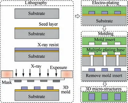
Fig. 22 Schematic illustration of LIGA process.
Marques and Kelly124fabricated nickel micro pin fin heat exchangers onto planar or nonplanar metal surfaces using a derivative of the LIGA micromachining process. During the process, a layer of X-ray resist is casted onto a stainless-steel plate. Then, SU-8 is exposed to X-rays. After the exposure and development, the nickel microstructures merge. Finally,the crosslinked SU-8 is removed via pyrolysis at 500°C, as illustrated in Fig. 23(a). The manufactured fin heat exchanger is presented in Fig.23(b),which is connected by fields of cylindrical fins with height-to-diameter ratios in the range of 1 to 4.Furthermore, Harris et al.125fabricated a cross-flow microheat exchanger with coolant channels of length 300 μm using LIGA, which was developed for the blades of gas turbine engines. Becker et al.126reported the manufacture of various microstructures with high aspect ratios and large structural heights via X-ray radiation lithography, electroplating, and plastic molding processes. They demonstrated that LIGA is the superior choice, especially for manufacturing microstructures with high aspect ratios. Marques et al.127confirmed that it is feasible to modify standard LIGA for the fabrication of high-aspect-ratio microstructures.An improved LIGA method is being developed for the fabrication of surfaces covered with high-aspect-ratio microstructures. First, a polymer is pressed,clamped, or wrapped onto a metal target surface without bonding to serve as a template for electroforming microstructures onto the target surface.The perforated sheet is produced either directly via lithography or via molding. A shroud was built via the modified LIGA, which is supported by an array with micro pin fins that are 500 μm high and 500 μm in diameter.128Harris et al.129described a process for producing a nickel micro cross-flow heat exchanger by embossing a sacrificial polymer mandrel using a LIGA-fabricated mold insert,which can be dissolved via the following process. The created heat exchanger consists of hexagon arrays; the length of each side of the hexagon is 250 μm; and the gap between parallel sides of adjacent hexagonal posts is 150 μm.Furthermore,they summarized approaches for producing a series of heat exchangers for diverse applications using derivatives of the LIGA micromachining processes.130
4.4.2. Energy-field-assisted micromanufacturing
With the increasing demands on the mechanical properties,heat resistance and fatigue performance of microparts in various domains, the use of high-strength materials is becoming increasingly common. However, via conventional fabricating processes, it is difficult to produce designed microstructures on difficult-to-deform materials due to their high deformation resistance. Therefore, energy-field-assisted micromanufacturing methods are introduced and investigated for realizing superior forming quality, reduced processing cost and increased operational efficiency. The special field-assisted methods include electrically assisted (EA) manufacturing,131UVassisted manufacturing132and electromagnetic forming(EMF).133Most of these methods can lower the flow stress or improve the material microstructures, which is beneficial to the performance enhancement of the final micropart.
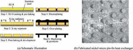
Fig. 23 A modified version of LIGA manufacturing process.124
The EA forming method has a variety of effects, such as softening the material,increasing the ductility,and eliminating the residual stress, which are mainly attributed to the electroplastic effect.134Fig. 24 illustrates the electronically aided microrolling process for creating microchannels on hard materials, in which a pulsed current is applied during the conventional rolling process. Due to the thermal and electroplastic effects, the deformation force is efficiently reduced, thereby enabling the production of hard materials, such as titanium alloys.Lei et al.135summarized the mechanisms of electroplasticity,which include the heating effect,the electron wind effect,the acceleration of vacancies, and the electropulsing effect.Meanwhile,the deformation characteristics of materials during the EA drawing, rolling and punching process were identified.Oh et al.136introduced the EA indentation method for surface texturing and tested the hardness in the electrically assisted area of SUS304 and titanium sheets. The temperature was low,which could prevent unnecessary heating in the manufacturing process. Ng et al.137produced microfeatures on Ti6Al4V and AA3003-H14 ultrathin sheets via the EA microrolling process, where improvement in the production of microtextures was successfully realized.Mai et al.138proposed the EA embossing process and demonstrated the feasibility and advantages of the method for fabricating microchannels on less formable materials, such as 316L stainless steel.
The ultrasonic field is another commonly used assistance technology. The UV can reduce the flow stress of metals due to the stress superposition effect and the acoustic softening effect. The mechanical properties, microstructures and surface qualities of the material can also change under the effect of UV. Meng et al.139applied a UV field to ultrathin superalloy sheets to realize improved formability, and they observed that the stress softening phenomenon that is induced by UV is weaker for Inconel 718 compared with soft materials, such as copper and aluminum alloys. Bunget et al.140designed a UV-assisted microextrusion setup,in which a substantial drop in the forming load was observed when the UV was activated and the surface quality of the microformed parts was substantially improved. Yang et al.141applied longitudinal and torsional vibration to the wire drawing process of titanium, and the surface quality of the processed wires was improved due to the change in the contact conditions between the workpiece and the die.Regarding the microtexturing process,Luo et al.142imprinted a cross-section microchannel on thin copper sheets via UV-assisted flexible punching, as illustrated in Fig. 25.The imprinting effect of the structure depended on the duration of the UV, and the optimal duration was demonstrated to be 0.5 s. Moreover, Liu et al.143developed a novel forming process that combined electrical and ultrasonic vibrationassisting fields for surface modification of the Ti6Al4V alloy.This hybrid method can lead to fewer dislocations, a deeper plastic deformation layer and a higher surface strength, while the inner grain size is increased substantially due to the thermal effect of the current.
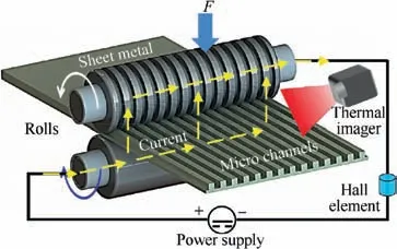
Fig. 24 Schematic diagram of EA microrolling process.
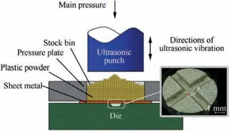
Fig. 25 UV-assisted imprinting process and a fabricated microchannel.142
4.5. Microscaled joining processes
The individual component for HPCCEs is manufactured directly by technologies mentioned above, and the fabrication of a complicated heat exchanger involves a substantial amount of microscale joining processes including brazing,welding,and diffusion bonding. Exchangers operate in extreme environments of high pressure,high temperature and strong vibration.Hence,the quality of the joints is crucial.Moreover,pipes and plates with tiny diameters and thicknesses in compact structures further increase the difficulty of the joining processes.13
4.5.1. Vacuum brazing
The brazing technique,which forms a bond by melting binder,is extensively applied in the traditional heat exchanger. The basic approach for fabricating PFHEs is to assemble the parting sheets, fins, sidebars, and top plates together in a fixture and to braze the assembly to form the heat exchanger core.Then, the fins are brazed to the separating plate via the dip brazing or vacuum brazing technique. The assembly is heated using radiation to the brazing temperature in a vacuum environment, which guarantees low oxygen partial pressure and promotes the chemical decomposition of oxides.The temperature route is affected by the dimension of the exchanger.144Gong et al.145investigated the influence factors of the brazing residual stress, which include the brazing temperature, the material properties, the pressure loading, the brazing gap,the dimension of the fin,and the plate thickness.Jiang et al.146presented another cooling approach for brazing 304 stainless steel plate-fin structures with nickel-based BNi2 filler metal.This new slow cooling approach substantially enhances the brazing performance via self-cooling to 620°C and quick cooling with dry nitrogen and wind cooling. In addition, Han et al.147,148used a new Inconel 718 as the stuffing to produce an Ni-based superalloy ultrathin-walled structure by vacuum brazing. They explored the effects of the brazing temperature and the particulate content on the wettability,the solidification behavior, the typical microstructural evolution and the mechanical properties of the brazed ultrathin-walled structure.The outer diameter of the used microtube is 0.9 mm, and the wall thickness is 0.05 mm. The brazing process was conducted at a temperature of 1423 K for 3 min.Then,the post bond heat treatment (PBHT) was performed, as illustrated in Fig. 26.They argued that the tensile strength with PBHT at 1013 K for 120 min is improved to 1488 MPa from 1191 MPa without PBHT.
Brazing is an efficient joining process under high vacuum degree and uniform heating,which is easy to realize.Although the preparation of fixer is tedious, many joints can be completed simultaneously by vacuum brazing.Besides,the surface quality of the brazed microparts is high comparing to other joining processes.
4.5.2. Diffusion bounding
The diffusion bonding process realizes a permanent connection between materials via the formation of bonds between atoms.A load is exerted by multiple flowing surfaces at temperatures of (0.5–0.8)Tm, where Tmis the melting temperature of the material. By imposing heat and pressure on the material instead of melting, a perfectly bonded part can be produced.The diffusion process is illustrated in Fig. 27. When the material is heated and pressurized, the microasperities come into contact and the oxide films are broken due to the plastic deformation.Once the temperature and pressure stabilize,the voids have shrunk and the oxide film is broken and decomposes due to the creep deformation and diffusion of atoms. Ultimately,the clean metal surface is increased and the atomic configuration approximates the grain boundary. In the end, the grains grow across the bonding surface,and the pores are eliminated.
The diffusion bonding method can efficiently improve the performance of a compact heat exchanger compared with the brazing. Chordia et al.149proved that a brazed PFHE can withstand a maximum pressure of 9 MPa, while the diffusion-bonded PFHE can withstand pressures of up to 20 MPa. Shiferaw and Broad150reported the development of the diffusion-bonded heat exchangers for a fuel gas heating system,which are flexible and can match the thermal duty with the available pressure drop by adjusting the cocurrent or the cross- or countercurrent flow, as shown in Fig. 28(a). In addition, He et al.151created and tested several monolithic and bonded stainless steel and nickel foam-tube heat exchanger modules, as presented in Fig. 28(b). The fuel–air heat exchanger was created successfully by combining the bonding procedure with the final sintering.Chen et al.152reported a heat sink plate that provides thermal protection for the vehicle and its subsystems at high speed. The heat exchanger is composed of titanium alloy or higher temperature titanium with a maximum temperature capability of 950 K. The 0.08-inch-thick regeneratively cooled heat sink plate consisted of two thin titanium plates that were etched deeply and diffusion-bonded via the hot isostatic pressing process. Meit et al.153fabricated an All-Cu micro-heat exchanger prototype by integrating direct molding replication and solid-state bonding.The active surface of this insert includes 26 parallel rectangular micro-protrusions with 178 μm average width, 750 μm center distance and 400 μm height of the straight-line portion, as presented in Fig. 28(c). The REL company7has successfully fabricated a silicon carbide/graphite body via a reaction bonding process,in which the green material can be formed via multiple methods, such as extrusion, isostatic compaction and warm molding. The ultimate structure has a fine and homogeneous grain size, and grains of alpha silicon carbide are combined by beta silicon carbide with remaining free silicon, as shown in Fig. 28(d).
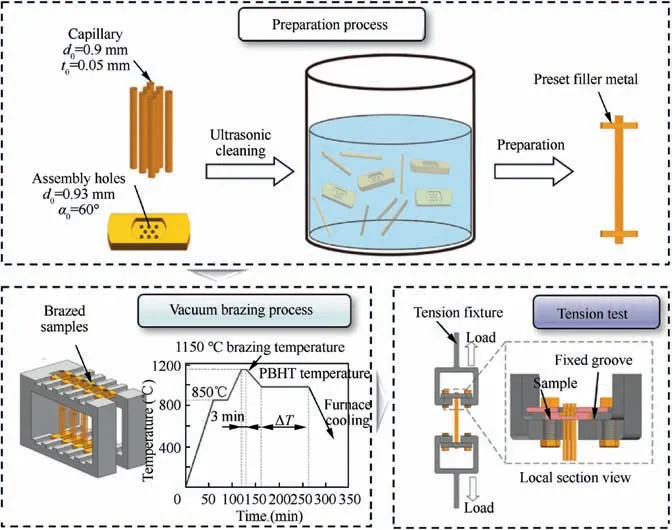
Fig. 26 Vacuum brazing and testing of ultrathin-walled structure samples.148

Fig. 27 Schematic illustration of diffusion bonding process.
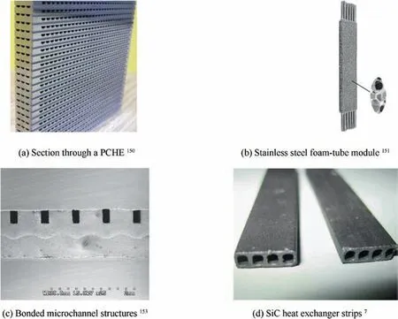
Fig. 28 Bonded heat exchangers.
Diffusion bounding has the similar advantages with brazing,such as high efficiency and desirable surface quality.However,the structural requirement is stricter than brazing because the pressure is needed to apply on the specimens.Thus,the diffusion bounding is mainly used for the joining of plate structures. Furthermore, the materials usually stay at high temperature for long time to ensure the grain growth and coalescence in diffusion bounding process, which is not appropriate to control the microstructural properties.
4.6. Comparison of different micromanufacturing modes
Table 3 summarizes recent achievements in micromanufacturing processes for compact heat exchangers.The multipass tube drawing process has become the leading method for fabricating microtubes for STHEs due to its advantages of higher efficiency and lower cost. However, the uniform control of the wall thickness and the microstructural performance of the tubular parts must be improved. In addition, cold tube drawing does not perform sufficiently well in the fabrication of difficult-to-deform materials, such as superalloys and refractory alloys; assistant fields, such as pulsed current, UV, and high temperature, must be introduced.Nevertheless, the interactions among the size effects, multiple fields, and the process configuration render difficult the manipulation of the quality of the microtubes.Microstamping produces microcomponents with ideal geometry mainly via plastic deformation.For fabrication, it has already been investigated as a potential method for volume production of micropins in PFHEs due to its high productivity and low cost and the outstanding mechanical properties of the microformed components. However, it remains to be improved in the aspects of thinning rate and smoothness. In contrast to microstamping, microembossing is a bulk-forming process for thicker plates. Since a large deformation force is required for inducing the material to fill in microchannels, the process can be applied only to softer materials such as copper and aluminum. Furthermore, the consistency of the microchannel dimensions is difficult to control in this process. Due to the apparent advantages of the micromilling and microturning processes in mass production,their suitability for various feature shapes and the larger variety of materials to which they can be applied compared with lithography and EDM,they are applied to the large-scale production of micropins for PCHE. However, the drawbacks of micromilling include poor surface finish of microparts, excessive material waste, uncontrollable tool run-out, and premature tool life. In contrast, photochemical machining is a relatively mature technology for manufacturing microchannels on sheet metals, which maintains the dimensional tolerance and does not create burrs or sharp edges. PCM is applicable to the available metals or alloys of any hardness within the thickness range of 0.013 to 2.032 mm.Compared with the subtractive micromanufacturing techniques, sintering and injection molding are often used to fabricate ceramic heat exchangers and are followed by the bonding process. Other techniques of micromanufacturing, such as LIGA, require molds and dies for implementing microinjection molding andsintering processes. Moreover, the ductility and mechanical properties of the fabricated microchannels are poor, which substantially affects the subsequent assembly and joining and the performance under extreme conditions. Although 3D printing processes can create various feature shapes with feature sizes of less than 0.5 mm,superalloys and refractory alloys cannot be handled due to the limitations of laser power.As an electroforming approach,LIGA can produce components with various materials that contain metals, plastics, and ceramics.Thus, it is frequently used to produce nickel and nickel alloy parts due to its ability to fabricate high-aspect-ratio parts with extreme precision. LIGA can fabricate features at the micron level. The main limitations of the LIGA technique are as follows: inability to produce curved surfaces, irregular arcing due to fragments becoming stuck in electrodes,and the underlying menace to adjacent electrodes of shockwaves.154
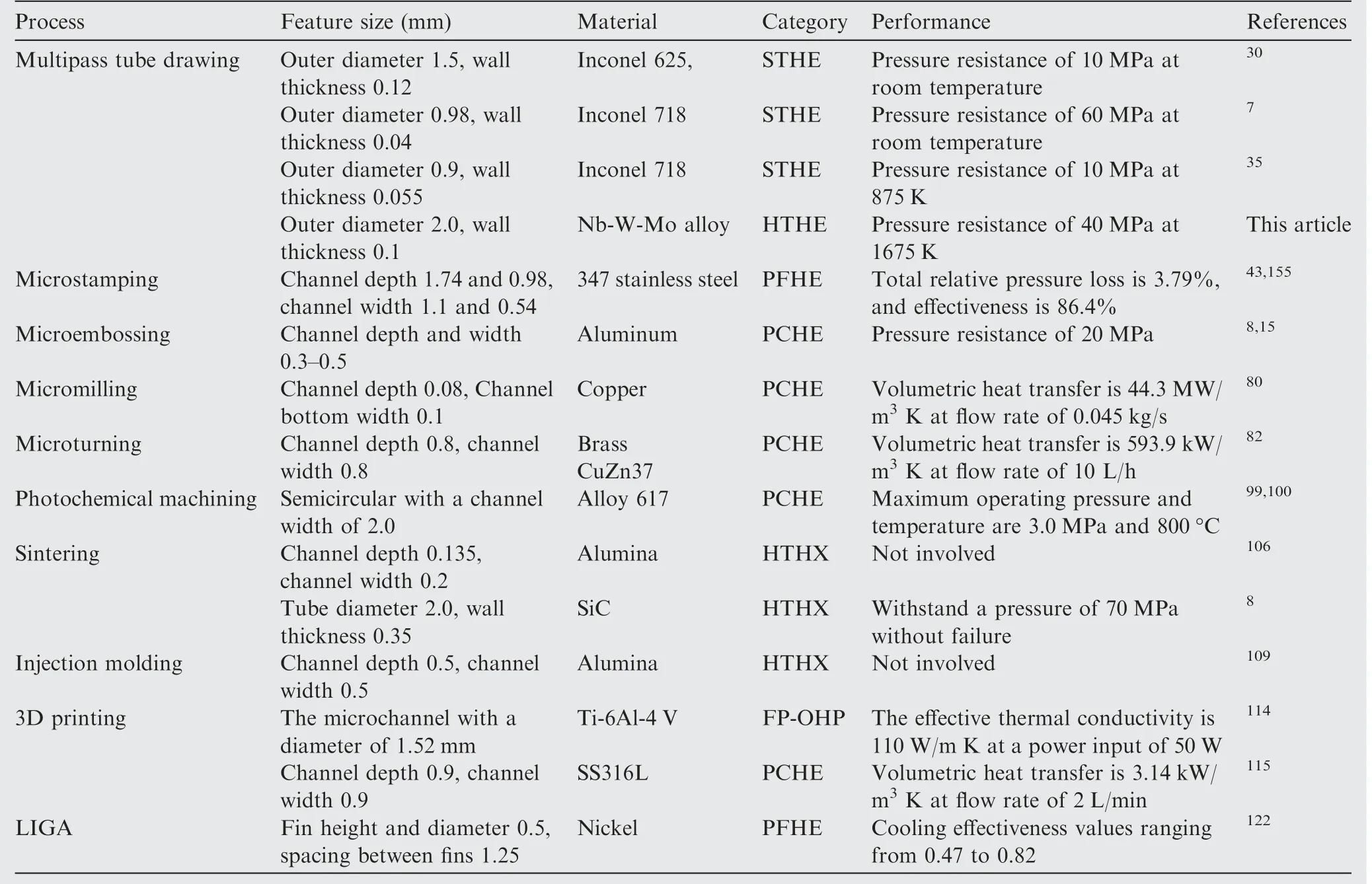
Table 3 Summary of recent achievements in micromanufacturing processes for compact heat exchangers.
The heat exchangers used in HPCCEs have a typic design process. First, the heat exchanger type is decided based on the working condition,which includes the serving temperature,working pressure, heat exchange area and structural design.Sequentially, a proper manufacturing method is selected by considering manufacturing and joining processes. The characteristic parameters of each technology are listed in Table 3 in detail, which provide a good reference for the design of compact heat exchangers based on different material categories.Last but not least,the integration or improvement of the manufacturing technologies may facilitate the improvement of designs.
5. Future research priorities
Nowadays, the micromanufacturing processes are rapidly developed and widely used in aviation, communication, and other industrial clusters.However,there are still some valuable and potential research priorities as below:
1)Interdisciplinary design based on material microstructure and property
The design of HPCCEs is currently based on the working conditions, which is a forward design process. The material microstructure and properties should be considered interdepartmentally in the future. Especially, the material selection affects not only the applicability of manufacturing processes,but also the heat exchange performance. The interdisciplinary design method is conducive to develop material potential and improve design efficiency and capability of energy management for HPCCEs.
2) Development and evolution of microscale hybrid processes
The limited hybrid processes have been proposed, which significantly improve the manufacturing quality and efficiency.However, the intrinsic mechanism of the microscale hybrid processes is still indeterminate, and the cooperative control of microstructural property and dimensional accuracy is difficult to ensure. Therefore, the combination of diverse energy fields is expected to introduce into the conventional micromanufacturing processes to accommodate the requirements of compact heat exchangers for HPCCEs.
6. Conclusions
In this study, an overview of the potential methods for fabricating compact heat exchangers for HPCCE applications was presented. These methods are categorized into four types of processes:microforming,subtractive,additive and hybrid processes.Compact heat exchangers,which benefit from their high surface-area-to-volume ratios, play a vital role in the HPCCE field. The realization of high-performance manufacturing of compact heat exchangers with conventional micromanufacturing technologies is challenging due to the usage of difficult-todeform or difficult-to-cut materials, the tight dimensional accuracy requirements and the harsh operational environments. The following conclusions are drawn from the review of current micromanufacturing techniques:
In manufacturing of STHEs working at ultra-high temperature environment, there is a trend of adopting multipass drawn microtubes with refractory alloys to replace the sintered ceramic microparts. Multipass tube drawing is a feasible technology for the difficult-to-deform metallic microtubes with an outer diameter of less than 1.0 mm and a wall thickness of dozens of microns.
Microstamping, microhydroforming, microembossing,microextrusion,and microrolling processes have attracted substantial interest in fabrication of microchannels due to their low cost and high efficiency, which are mainly used to make PFHEs and PCHEs. In addition, the energy fields including electromagnetic, electronic, ultrasonic, high-pressure and high-temperature, are gradually introduced into the micromanufacturing processes to realize the coordination control of microstructural property and dimensional accuracy.
Subtractive micromanufacturing processes, such as microcutting, laser-beam micromachining, micro EDM, and photochemical machining, help drive the fabrication of compact heat exchangers and provide stepping stones toward new and more efficient fabrication processes in the future. These technologies are mainly applied in PFHEs and PCHEs. However, the subtractive processes have the disadvantages of excessive material waste, low efficiency and environmental hazard.
Microscale additive manufacturing processes enable layerby-layer fabrication of complex parts from metals, ceramics,polymers, and composites with features that are unobtainable via conventional manufacturing. They are usually applied to the ultra-high temperature material for HTHEs, and have attracted extensive attention for the integrated fabrication of customized heat exchangers. One disadvantage of using an additive manufacturing process is the high cost of finegrained powders.Another problem with using an additive process for mass production is that it is impossible to produce microparts that exhibit the optimal appearance and finishes while guaranteeing the optimal mechanical properties, and subsequent manufacturing methods, such as polishing are required for improving the surface quality.
Vacuum brazing and diffusion bonding are currently effective methods for joining microparts in heat exchangers for HPCCEs. Vacuum brazing is widely used to join microscale tubes and plates in STHEs, PFHEs, and PCHEs. Whereas,the diffusion bonding is mainly applied to PFHEs and PCHEs.Besides, the diffusion bonding usually deals with dissimilar materials. However, the reliable joining of heterogeneous interfaces remains a substantial challenge in the microjoining process, and further investigation is required.
The fabrication process of compact heat exchangers involves multiple materials, multi scales and multiple passes.Both interdisciplinary design methodologies and hybrid micromanufacturing processes derived from current microfabrication techniques, are necessary for overcoming the key issues encountered in the production of compact heat exchanger for HPCCEs.
Acknowledgements
The authors would like to acknowledge the funding support to this research from the National Natural Science Foundation of China (Nos. 51635005, 51975031 and 51605018) and Defense Industrial Technology Development Program of China (No.JCKY2018601C207).
 CHINESE JOURNAL OF AERONAUTICS2021年2期
- CHINESE JOURNAL OF AERONAUTICS的其它文章
- Recent active thermal management technologies for the development of energy-optimized aerospace vehicles in China
- Electrochemical machining of complex components of aero-engines: Developments, trends, and technological advances
- Recent progress of residual stress measurement methods: A review
- Towards intelligent design optimization: Progress and challenge of design optimization theories and technologies for plastic forming
- A combined technique of Kalman filter, artificial neural network and fuzzy logic for gas turbines and signal fault isolation
- Analytical method of nonlinear coupled constitutive relations for rarefied non-equilibrium flows
