Electrochemical machining of complex components of aero-engines: Developments, trends, and technological advances
Zhengyang XU, Yudi WANG
National Key Laboratory of Science and Technology on Helicopter Transmission, Nanjing University of Aeronautics and Astronautics, Nanjing 210016, China
KEYWORDS Aeroengine;Electrochemical machining;Hybrid machining;Machining process;Manufacturing;Nontraditional machining
Abstract Because of several advantages, such as no tool wear, independence on the mechanical properties of the material, and high machining efficiency, electrochemical machining (ECM) has become a viable method for machining components in numerous industrial applications, particularly in the manufacture of typical aero-engine components with complex structures fabricated from materials that are difficult to cut. This paper highlights the current developments, new trends, and technological advances of key factors of ECM,such as electrochemical dissolution characteristics of novel difficult to cut materials which are often used in aero-engine,numerical simulation of electrochemical process,design for the complex profile and structure of cathode tool,flow field simulation and design for uniform electrolyte flow, and innovation of electrochemical machining or hybrid methods which reflect the state of the art in academic and industrial research on electrochemical machining in aero-engine manufacturing.
1. Introduction
Aero-engines are among the most complex industrial products.With the rapid development of the aviation industry, the demand for aero-engines is constantly growing. For example,Rolls-Royce expects about 68,000 deliveries over the period from 2012 to 2031, for which the market value is expected to reach $975 billion.1For GE Aviation, the market amounted to $7.2 billion, while the new engine market was $4.9 billion in 2011.2With the improvement of performance requirements of aero-engines, such as higher reliability, longer life, greater fuel efficiency, higher thrust as well as cleaner and quieter operation,many novel technologies will be used in the components of aero-engines, including new high-strength lightweight materials and more complex structures. In addition, the machining accuracy and surface quality of components must meet a higher standard. There is an extensive and pressing need for manufacturing technologies to handle the challenges of demands for aero-engines.Many unconventional processes,such as electrochemical machining (ECM), electro-discharge machining (EDM), laser beam machining (LBM), electron beam machining (EBM) and ultrasonic machining (USM)are widely used for the manufacturing of aero-engine components.Because of its unique advantages,such as independence on the mechanical properties of the material, no tool wear,high machining efficiency, and low cost, electrochemical machining is one of the most suitable technologies for components with complex structures fabricated from difficult-to-cut materials.
In recent years, with the development of aero-engine, electrochemical machining technology has shown more advantages in processing quality, efficiency and cost. Academic circles have carried out a lot of research work on electrochemical machining technology for complex components of aeroengine with difficult-to-machine materials, and made remarkable progress. In the industry, ECM technology has also been applied to the manufacture of complex key components of aero-engine, and the effect is remarkable. In this paper, the research progress of electrochemical machining technology for aero-engine complex parts in recent years is described.Several key factors of electrochemical machining technology,including material dissolution characteristics, machining process simulation, electrode tool design and electrolyte flow field design,are discussed in detail.Then,the innovation of electrochemical machining method and the actual processing results for typical complex parts are discussed. Finally, the development trend of electrochemical machining technology for aero-engine complex parts is analyzed and prospected.
2. ECM and its application in aero-engine
Electrochemical machining(ECM)is a nontraditional machining process. As shown in Fig. 1, the workpiece is the anode,and the pre-shaped tool is the cathode. DC or pulse voltage(10–40 volts) is applied across the workpiece and tool. During the process,the cathode tool moves towards the workpiece and keeps a very small inter-electrode gap (0.05–0.6 mm). The material of the workpiece is removed by the mechanism of anodic dissolution, which is governed by Faraday’s laws of electrolysis.3,4The current density is usually 20–200 amperes per square centimeter. The electrolyte (NaCl or NaNO3aqueous solution) flows at high speed (10–60 m/s) through the inter-electrode gap to keep the reaction steady and remove the dissolution product,bubbles,and reaction heat.ECM produces an approximate mirror image of the tool on the workpiece.
There are several major advantages of ECM, as shown in Fig.2.Because it is a contactless machining method,it is suitable for difficult-to-cut materials, regardless of their hardness and strength.During the process,the shaped cathode tool does not wear because only hydrogen is released on the cathode.Moreover,high material removal rates can be achieved as well as high machining accuracy and good surface quality without the occurrence of deformation, microcracks, residual stress, a recast layer, or heat affected zones.5–8In addition, due to the cost of pre-development of tools and fixtures as well as the investment required for unique machine tools, ECM is specifically used in large bath-size production to reduce cost.
In contrast, ECM also has some disadvantages. The main aspect is the long production preparation cycle, especially for the tool electrode design required for complex profile processing, which often requires repeated corrections. In addition,since the ECM is a multi-field coupling process and there are many influencing factors, so the machining accuracy and machining stability are difficult to control.
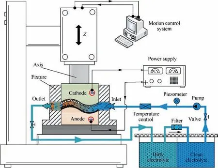
Fig. 1 Schematic of ECM.
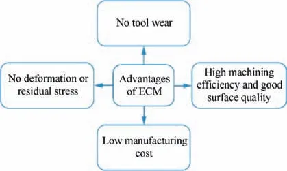
Fig. 2 Several major advantages of ECM.
In recent years, there have been three major areas of research on ECM. First is precision electrochemical machining,which focuses on the improvement of machining accuracy and surface quality of ECM. Several main aspects, such as tool shape and structure design, flow field design, process calculation and simulation,parameter optimization,and novel machining mode,are the main targets of research.The purpose is to improve the electrolyte flow conditions in the interelectrode gap, enhance the localization of anodic dissolution,and keep small, stable gaps to achieve higher machining accuracy, good surface quality, and better process stability. The second area is microelectrochemical machining in which metal microparts and microsurface structures could be achieved by using high-frequency pulse power and a specific electrolyte solution to enhance dissolution localization.9,10The third research area is electrochemical hybrid machining in which electrochemical machining and other energy forms are combined to produce parts at the same time and in the same processing zone to enhance the advantages of ECM and other processes and to minimize the potential disadvantages of an individual technique. ECM grinding and electrochemical discharge machining are typical examples.11–13Fig. 3 shows the three research areas of ECM.
Many components in aero-engines could be made by ECM,as shown in Fig.4.The most important type is complex surface parts, for example blades, blisks, casings, impellers, diffusers,and so forth. The materials used for the fabrication of these parts are often nickel-based superalloys and titanium alloys,which are difficult to machine. The structures are often very complex, and the requirements for machining quality and efficiency are often high. Thus, ECM is an effective method to manufacturing these components. For example, compressor blisks are the most important components in aero-engines.There are several manufacturing methods to machine blisks,such as linear friction welding (LFW), high-speed cutting(HSC), and electrochemical machining. LFW is an effective method for welding the blades with the disk.It is very suitable for the large scale blisks of fans and low-pressure compressors in aero-engines to reduce the cost of materials.Multi-axis highspeed cutting is a mature method to machine blisks, especially for blisks fabricated from easy-to-cut materials with wide cascade passages. Because of these advantages, ECM is the preferred method to machine blisks fabricated from difficult-tocut materials with narrow cascade passages. Fig. 5 shows the proportions of various machining methods for the production of blisks.Table 1 shows the comparison of three main machining methods for blisk. With the development of aero-engines,in which more and more complex components and difficult to cut materials are used, ECM will have increasing potential as an effective method for the fabrication of aero-engine components.
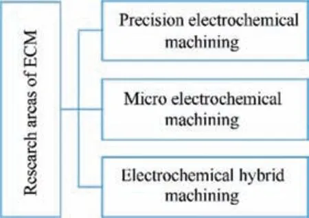
Fig. 3 Three research areas of ECM.
3. Research and application of ECM in aero engine
This section gives a specific overview of the research advances and technological capabilities of several main aspects of ECM process,followed by a description of some applications for the production of aero engine components. The main aspects of ECM, as shown in Fig. 6, are materials dissolution characteristics,the calculation and simulation of the machining process,the design of the cathode tool shape and structure, the flow field design, the optimization of cathode tool movement, and the innovation of the machining method.
3.1. Materials dissolution characteristics
The electrochemical behavior of metal materials is the basis of electrochemical machining research.The polarization and passivation characteristics, decomposition voltage, current efficiency of materials are the important elements that influences the selection of machining mode and parameters, and the prediction of processing result. The electrochemical behavior of conventional metal materials has been well studied. However,there are many novel difficult to cut materials such as titanium alloys,titanium aluminide intermetallics,nickel-based superalloys, and single-crystalline materials which are often used in aero-engines. The study of their dissolution characteristic is still insufficient. Thus, many studies have focused on the electrochemical dissolution characteristics of titanium alloys, titanium aluminide intermetallics, nickel-based superalloys, and single-crystalline materials, which are often used in aeroengines to improve the surface quality, machining efficiency,and stability.7,14–20
To increase the efficiency of jet engines, hard-to-machine titanium-and nickel-based alloys are in common use for blade and disk materials. Basic studies on the electrochemical machinability of selected modern titanium- and nickel-based alloys for aero-engine components have been carried out.7The experimental feed rate results as a function of current density for an ECM sinking operation with a cylindrical tool electrode and external flushing were compared to the theoretical dissolution behavior according to Faraday’s law.
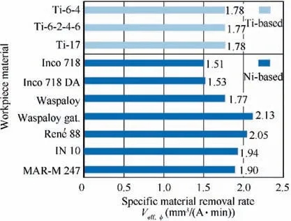
Fig. 7 summarizes the averaged effective material removal rates of all tested alloys. Because there was almost no difference in the results for various electrolyte concentrations, the linear curves were combined to one function, namely, Veff,Ø,the average effective material removal rate.All titanium alloys showed almost identic Veff,Øvalues with 1.78 mm3/(Amin)adjusted.
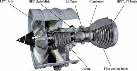
Fig. 4 Components that could be made by ECM in an aero-engine. (example: Rolls Royce Trent 1000 engine).
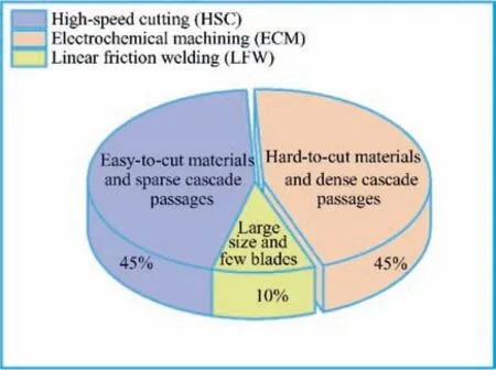
Fig. 5 Proportion of currently used machining technologies for production of blisks.
In the case of the nickel-based alloys, more fine-grained microstructures led to a better electrochemical machinability and dissolved faster. Thus, the powder metallurgically manufactured superalloys showed the best electrochemical machinability. Generally, the nickel-based alloys dissolved faster than titanium-based alloys.7In the machining of cast superalloys,the microstructure of the materials,especially in terms of carbon and carbides,interfered with the stability of the electrochemical dissolution. The dissolution process was more stable and efficient in NaNO3solution at 40°C and a 10%concentration.21
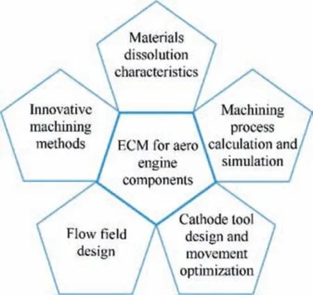
Fig. 6 Several main research aspects of ECM for aero engine components.
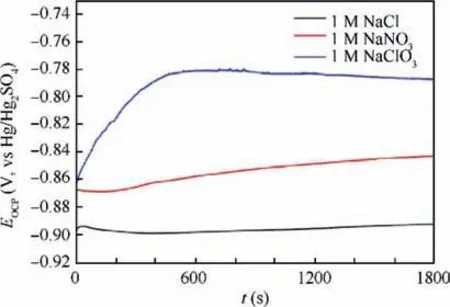
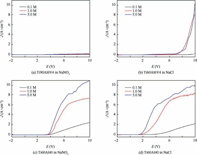
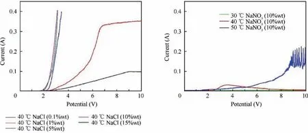
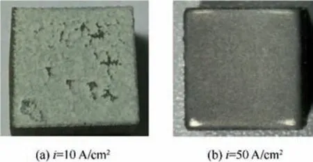
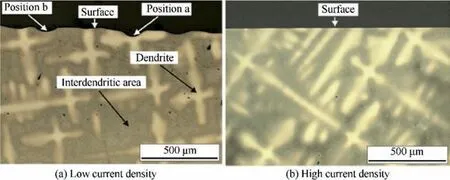
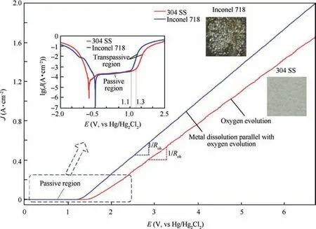
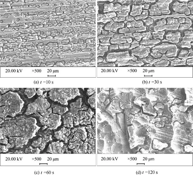
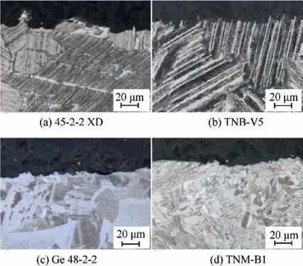
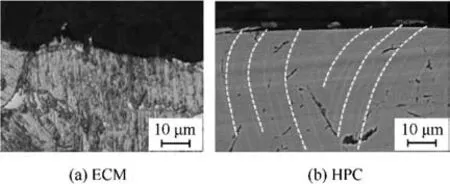
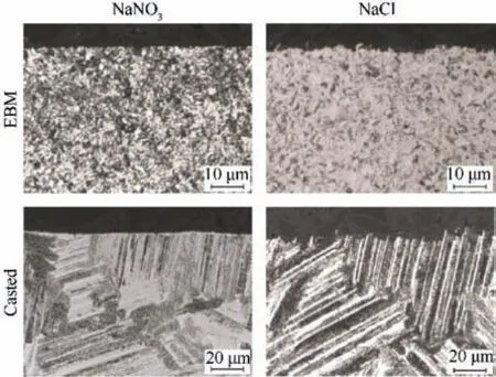
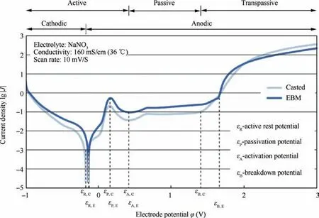
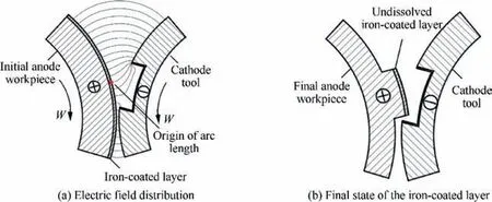
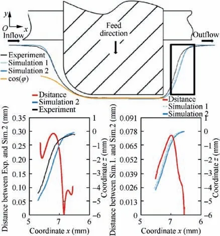
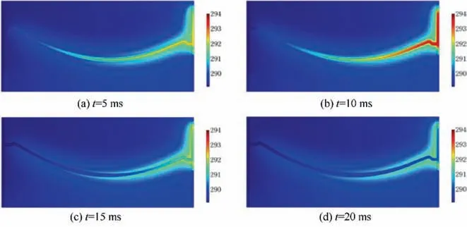
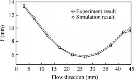
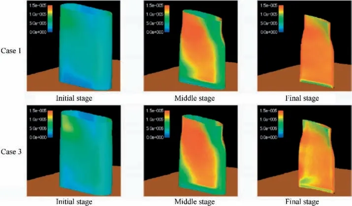
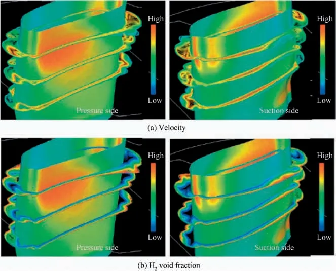
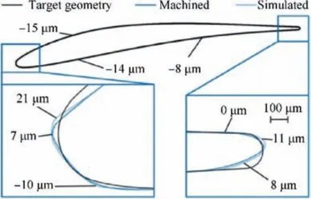
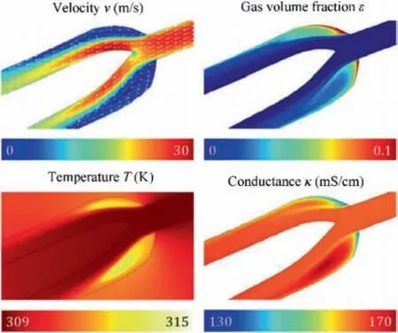
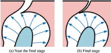
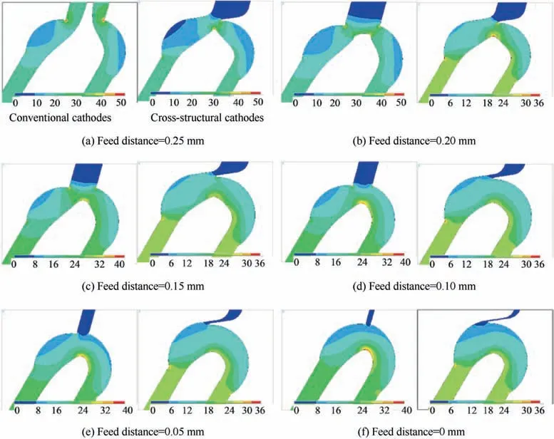
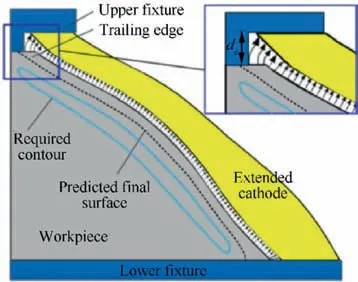
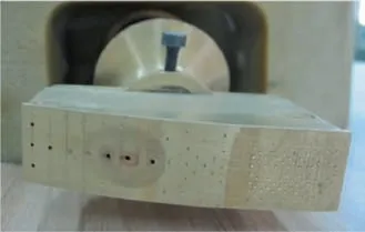
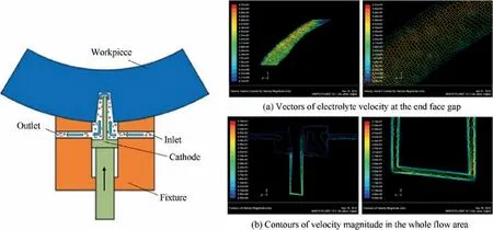
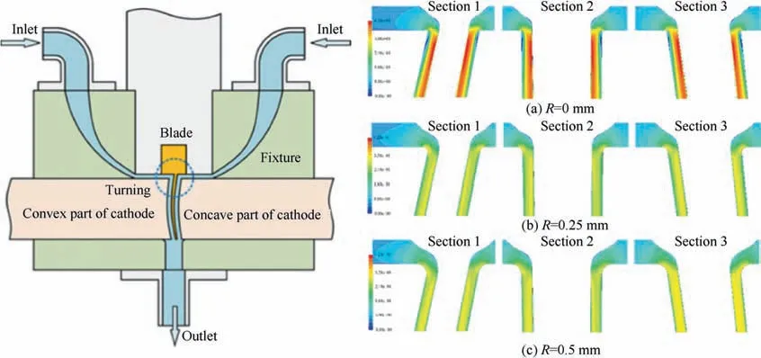
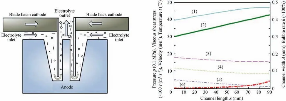
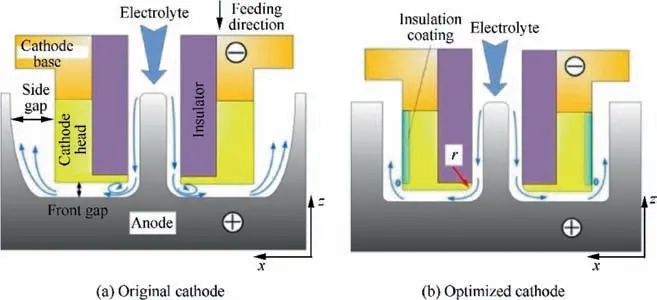
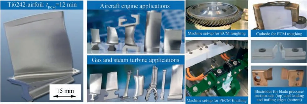
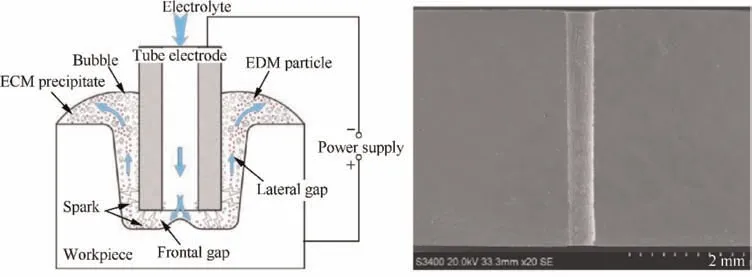
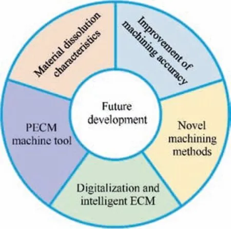
The problem during the ECM process for titanium and its alloys is the formation of a dense oxide passive layer, which inhibits the dissolution process. Without the knowledge of the appropriate processing parameters, industrial application is impossible.15The dissolution behavior and oxide passive layer formation of various titanium alloys in aqueous electrolytes has been investigated.15,22,23The existence of a natural oxide layer on top of Ti90Al6V4 and Ti60Al40, which are often used in aerospace applications,24,25was verified by Electrochemical Impedance Spectroscopy (EIS). The oxide layer on Ti60Al40 is less distinct than that on Ti90Al6V4. The oxidation power of the used electrolyte anions increases in the order Cl- Table 1 Comparison of three main machining method for blisk. Fig. 7 Effective material removal rates of analyzed alloys.7 Halide-containing electrolytes are more suitable for titanium alloy ECM. The anodic polarization curves and the open-circuit potential of Ti60 with sodium nitrate and sodium chloride solutions were obtained. Compared to the sodium nitrate electrolyte, the sodium chloride electrolyte is more active and chloride ions can chemically interact with the oxide layer. Thus, better electrochemical machinability is achieved using the sodium chloride electrolyte.22,23The same is true for the Ti40 alloy.It was found that an aqueous mix of sodium chloride and potassium bromide provides the optimal electrolyte and that the surface quality of the Ti40 workpiece is improved by using a pulsed current of 1 kHz rather than a direct current.26Further, some other mixture solutions also met the requirements of other specific materials. The results of electrochemical dissolution characteristics demonstrated that the current efficiency and surface quality of TB6 titanium alloy was enhanced by using a mixture composed of NaCl and NaNO3electrolytes, whereas the decomposition voltage decreased.27The anodic behavior of TB6 titanium alloy was also investigated by linear sweep voltammetry, cyclic voltammetry, electrochemical impedance spectroscopy, and chronoamperometry.18 Fig. 8 Time dependence of EOCP for Ti90Al6V4 measured in various electrolytes.15 The optimizations of parameters, such as electrolyte concentration, temperature, operating voltage, and electrolyte inlet pressure, for improving the surface quality of titanium alloy were studied.Concentration and temperature are important factors influencing electrochemical dissolution. The concentration of the electrolyte influences the dissolution potential and transpassive behavior.To destroy the oxide layer effectively and stabilize the dissolution,a high concentration is essential. When the temperature of the electrolyte is under 30°C, Edissclearly increases22,23as shown in Fig. 10. Current density is also an important factor in ECM.A high current density during the process always means a high material removal rate and high surface quality. For Ti60 alloy machining22,23at a high current density of more than 20 A/cm2, it is necessary to achieve good ECM stability, efficiency,and quality, as shown in Fig. 11. The same result could be achieved in research on a nickel-based single-crystalline material.16Low current densities lead to inhomogeneous electrochemical dissolution. A preferential dissolution of dendritic areas due to an inhomogeneous element distribution of Re,W, Ta, Ti, and Co was detected for low current densities,resulting in a rough surface appearance.High current densities result in very high metal removal rates and smooth surface appearances irrespective of the element distributions. Current densities beyond 1 A/mm2yield more homogeneous dissolution rates. This resulted in better surface qualities of LEK94-samples machined at high current densities, as shown in Fig. 12. Although a high current density is more suitable for the ECM process, research on electrochemical dissolution behavior at low current density is also necessary because there are specific process modes with low current density. The dissolution behavior of Inconel 718 at low current density in a NaNO3solution was studied.14The anodic polarization curves of Inconel 718 are plotted in Fig.13.In the passive region,only a slight increase in the current density is occurred with increasing potential. This can be attributed to the presence of a compact air-formed film on the initial surface. The passive region of 304 SS extends to around 1.3 V which is higher than the 1.1 V of Inconel 718, indicating that the air-formed film on Inconel 718 is easier to break for increasing potential in NaNO3. As shown in Fig. 14, the selective corrosion area increased with time elapsed, and more products were formed on the surface. The formation of solid black products was investigated and discussed. It was found that niobium plays an important role in the dissolution of Inconel 718 at low current density. The electrochemical machinability of γ-titanium aluminides has also been researched in several papers.17,28–31Four typical γ-TiAl materials, namely, GE 48-2-2, TNM-B1, 45-2-2 XD,and TNB-V5, were studied. Unlike previously investigated titanium alloys, the γ-TiAl alloys show higher material removal rates. The amount of aluminum could account for the higher current efficiencies.Therefore,γ-TiAl alloys,having roughly a five times greater amount of aluminum,show higher material removal rates. Furthermore, all of the investigated materials show good machining behavior in ECM.28 Fig. 9 Determination of starting voltage for dissolution of Ti90Al6V4 and Ti60Al40 in various electrolytes (scan rate 50 mV·s-1).15 Fig.10 Polarization curves for Ti60 alloy in sodium chloride with various concentrations (left), and current–voltage curves for Ti60 in sodium nitrate electrolyte with 10% concentration and various temperatures (right).23 Possible influences on machining were investigated by rimzone analyses and EDX analyses. No influence of the process or the electrolyte could be recognized. Nevertheless, cross sections showed differences in the dissolving behavior of the different material phases, as shown in Fig. 15. ECM is always competing with conventional manufacturing methods, such as high-performance cutting (HPC). To show the capability of ECM for machining of γ-TiAl alloys, Fig.16 shows a comparison of these two technologies.It is remarkable that the surface roughness of the HPC material is much better.By HPC,a surface roughness of 0.3 μm can be achieved. Using unpulsed ECM, the best surface roughness of 2 μm was achieved. Nevertheless,the HPC rim zone shows a deformation of the lamellae. ECM is free of thermal and mechanical loadings;therefore, the lamellae are not affected.28For optimization of the machining parameters, orthogonal experiments were conducted to study the effects of the process parameters on the material removal rate (MRR), surface roughness (SR), and machining gap (MG) in a sodium chloride aqueous solution.The results of the experiments were analyzed by the grey relational analysis method.The results indicated that the electrode feed rate has a crucial effect on the MRR, SR, and MG, and the best parameter combination was determined.30 Fig. 11 Surfaces produced by ECM at different current densities.23 Furthermore, the high cycle fatigue (HCF) behavior of ECM machined GE 48-2-2 was studied.29The specimens showed typical thermally and mechanically non-affected ECM surfaces. Furthermore, an HCF test procedure was described.Various specimens exhibited a roughly equal failure moment Mb≈2.2 N·m for 50% failure probability and thus showed the same HCF as broached or wire EDM Inconel 718. For low-pressure turbines and high-pressure compressors γ-TiAl is, in principle, a possible replacement material for Inconel 718 in the turbomachinery industry. Regarding the low density of γ-TiAl, the specific HCF is higher than Inconel 718. The differences between cast and electron-beam-melted(EBM) γ-TiAl TNB-V5 regarding their ECM behavior were investigated.31The machining differences were caused by their specific microstructures.Due to the fine grain size of the EBM material, a more homogeneous dissolution behavior occurs,which leads to better surface roughness, as shown in Fig. 17.The breakdown potential of the EBM material is higher, as seen in the potentiostatic polarization curves in Fig. 18. Fig. 12 Surfaces of machined samples with low and high current density.16 Fig. 13 Polarization curves of Inconel 718 and 304 SS in NaNO3 solution.14 Fig. 14 SEM images of corroded Inconel 718 specimens at 2 A·cm-2 for various corrosion times.14 Fig. 15 Cross-section analysis.28 Fig. 16 Rim-zone comparison of 45-2-2 XD.28,32 Fig. 17 Cross sections of electrochemical machined TNB-V5 with different microstructures and different electrolyte systems.31 Fig. 18 Current density–electrode potential of casted (c) and electron-beam-melted (e) TNB-V5.31 Fig. 19 Principle of the iron coating.39 Stray corrosion is a common phenomenon that occurs at the surface adjacent to the machining area in the machining of titanium alloy or nickel-based alloy, which will cause uneven metal dissolution and poor machining quality. Many studies have focused on improving machining accuracy by localizing ECM dissolution.33–38A method to reduce stray current attack by using an iron coating on the surface of the anode workpiece in a NaNO3solution was investigated, as shown in Fig. 19.39Because the iron coating is passivated at low current densities and can be easily applied or removed, it can be used to reduce the stray current attack. The η-i curves of a nickel-based alloy, Inconel 718, show that its dissolution efficiency is higher at low current densities, indicating poor localization and severe stray corrosion during ECM. The results show that the iron coating on the surface of the workpiece significantly improves the machining accuracy.It reduces stray corrosion and the amount of stray removal on the nonmachined top surface of a convex workpiece. In one study,another way of reducing stray corrosion by a gas-mixed electrolyte was studied.40The results show that with an increase in the air concentration in the electrolyte, the area of stray corrosion will be reduced. The reason is that the nonlinearity of the electrolyte will increase to restrain the corrosion of a large inter-electrode gap when the air concentration proportion is enhanced.An air concentration of 0.55 is a superior choice in the gas-mixed electrochemical machining of titanium alloy TC4. In summary, it is very important to master the dissolution characteristics of materials for achieving high surface integrity and high efficiency of electrochemical machining. Future research on the dissolution characteristics of new materials will continue. For passivation materials such as titanium-based alloys, how to effectively inhibit local pitting corrosion and reduce stray corrosion will be the key research area. For nickel-based alloys, it is necessary to master the dissolution characteristics under different processing conditions. In addition, in order to improve the surface integrity of workpiece,high current density is often used in traditional electrochemical processing,which will cause the total current of ECM to be too high for large workpiece. How to achieve stable processing under low current density while ensuring better surface integrity is also an important research work. Fig. 20 Modelling performance dependence on integration level of physical effects and comparison to experiment.42 It is very difficult to precisely describe the ECM machining process with a model because there are multiple physical and chemical phenomena, including the electric field, fluid flow field,electrochemical dissolution and so forth, during the process.Earlier research was always based on a simplified electric field model or an empirical formula. Thus, there are obvious errors between simulation and real conditions. For the machining of components in an aero-engines, especially complex surface structures such as blades or blisks, it is necessary to calculate and simulate the machining process more precisely because of the requirement for high accuracy. The purpose of modelling simulation is to predict the final shape of a workpiece, which is the direct problem, and to design the correct cathode shape depending on a given anode geometry, which is the inverse problem. In Fig.20 a comparison of experimental results,two different 3D multi-physics simulations, and the established cos θmethod is shown for the DC-ECM sinking of a leading edge rounded cuboid.41Simulation 1 mainly considered the electric field in the inter-electrode gap, whereas in Simulation 2, the heat transfer and fluid flow are also modelled.42The cos θmethod is the traditional method to predict the final shape of a workpiece or to design the cathode contour when the angles of the profile normal and cathode feeding direction are less than 45°. It can be seen that simulated results show good agreement with the ECM experiment results.The largest difference between the calculated and the experimental result is located in the side gap at the outflow position in which the maximum deviation is below 300 μm. Comparing the results from both simulations,because of Joule heating and the linear correlation of conductivity and temperature, the material removal rate is higher for Simulation 2. The results demonstrate the potential of multi-physics simulation for predicting the complex surface of a workpiece and optimizing a complex cathode design.41 Numerical models for the electrolyte flow have been developed.Jain et al.43simulated ECM processes in which the electric and flow fields affect the metal removal rate. Hourng solved a one-dimensional, bubbly two-phase44flow field to accurately predict the workpiece shape and the variations of electrolyte properties between electrodes.45 However,the surfaces of blades are often complex,and the curvature of workpiece shapes varies widely,as well as the electrolyte flow is two-dimensional.These one-dimensional models of fluid flow are inadequate for an electrode with complex shape. Multi-dimensional analysis is necessary to accurately model the local distributions of flow and temperature for cases in which the workpiece surfaces are complex. Using a twodimensional flow model,Hourng and Chang were able to compute the temperature increase along the flow stream under equilibrium conditions taking into account the void and other process parameters.In addition,Chang and Hourng developed a two-dimensional two-phase numerical model to predict the thermal-fluid field.45A finite Fourier series, constructed from even and odd harmonics, is used in the electrode representation to reduce the relative errors. In addition, the twodimensional electric potential field is solved, and a twodimensional two-phase model is used to simulate the flow field during electrochemical machining. The results showed that if the curvature of the electrode shape varies markedly, a onedimensional model cannot obtain the details of the gas phase distribution. In a two-dimensional two-phase model, the detailed distribution of the volume fraction of the hydrogen gas phase can be obtained so that the result is closer to the experimental data. Thus, compared to a one-dimensional model, a two-dimensional two-phase model can simulate and predict the machining process more precisely. Fig. 21 Temperature distribution during one period.50 Fig. 22 Comparison of the workpiece profiles obtained by simulation and experiment after 30 min.50 Smets et al.46developed a model based on the complete convection–diffusion equation.They showed that the temperature transient curve during the pulse off time comprises two parts.In the first part, most of the heat is transported away by the electrolyte due to convection.In the second part,the fall in temperature is more gradual as heat flows from the electrode across the thermal boundary layer and into the electrolyte.Therefore,the second part has a much higher time constant than the first.47On this basis, to improve calculation efficiency, several modified numerical models to calculate the averaged and pulsed temperature history were developed.48,49Their quasi-steady-state short-cut(QSSSC) model is capable of calculating the average temperature until a certain time period and then switching over to smaller time steps to determine the cyclic temperature variation over the next few cycles. To further decrease the expense of calculation and increasing efficiency, an algorithm was introduced to simulate changes in workpiece shape in the pulse ECM process based on the quasi-steady-state short-cut (QSSSC) approach for modeling the temperature evolution.50The temperature distribution of pulse ECM is shown in Fig. 21. The assumption is made that the geometry structure is fixed before the system reaches the QSS, and the material removal is calculated by the current density when the QSS is reached.Simulation results indicate that the simplified algorithm is convenient for the calculation of the shape change of the electrodes. The predicted profile obtained by simulation agrees well with the experiment results,as shown in Fig.22.Thus,the validity of the simplified algorithm is verified by the comparison of workpiece profiles obtained by simulation prediction and experiments. Fig. 24 Dissolved volume distributions on the pressure surface.52 Fig. 25 Contours of velocity and H2 void fraction at various spanwise sections and dissolved volume distribution on blade surface.52 The numerical models for describing the ECM process of blade fabrication in a turbomachine have also been analyzed frequently.Paczkowski et al.developed an ECM model to predict the machined surface shape evolution of a blade and the distribution of physical-chemical parameters inside the inter-electrode gap. The variations of velocity, pressure,temperature, and volume fraction of the hydrogen gas phase and the electrolyte liquid phase were demonstrated and analyzed.51Fujisawa et al.52developed a multiphysics model and a numerical procedure to predict the three-phase and three-dimensional ECM process, as well as the final shape of a blade. Fig. 23 shows the nature of the flow around the tip.The void fraction of hydrogen is particularly high around the trailing edge,and this strongly affects the temperature distribution. These flow results indicate interaction among the flow, thermal, and electric fields. The non-uniformity of the flow affects the dissolution on the metal surface.Fig.24 shows the dissolved volume on the pressure surface. The numerical results indicate that the effects by Joule heating and hydrogen bubbles are dominant,and the dissolution is relatively uniform and enhanced by the narrow gap. Fig. 25 shows the velocity and H2void fraction contours at various spanwise sections and the dissolution volume distribution on the metal surface.This figure indicates that the gap size between the workpiece and the tool is the primary parameter in the ECM process for a compressor blade.52The multiphase flow as well as the thermal and electric fields between the tool and the blade were numerically investigated.The results indicate that multiphysics simulation is useful and essential for the prediction and analysis of an ECM process. The accuracy of the modelling simulation is obviously improved. An interdisciplinary simulation model of the ECM process for aero-engine blades was developed53,54based on the anodic metal dissolution by Faraday’s law and electric field modelled by the Maxwell equations. In addition, the electrical properties of the electrolyte were modelled with Navier–Stokes equations and the turbulence model. Gas evolution was described by the Butler–Volmer equation, and the influence of non-conductive hydrogen on the electrical conductivity κ of the electrolyte was approximated by using the Bruggemann equation.With the integral model describing the process,more precise simulation could be achieved, as shown in Fig. 26. However, there is still a greater deviation between the machined blade contour and the nominal contour data, especially at both edges of the blade. This may be attributed to the severe change of fluid flow and the consequent physical effect, as shown in Fig. 27. Due to the sharp edges, a dead water region develops,process heat and hydrogen gas accumulate,and the electrolyte conductivity will be changed.Further,the velocities of electrolyte across the two side of the blade are different, resulting in a change in the gas volume fraction and temperature distribution,which leads to the difference in material dissolution and the machining deviation. Fig. 26 Comparison of simulation and machined geometry.53 Fig. 27 Phenomena at the trailing edge towards the end of sinking.53 Fig. 28 FEM method for cathode profile design.61 The simulation calculation of electrochemical machining process is very important for analyzing the machining state and predicting the profile of workpiece. Because the process of electrochemical machining involves multi-physical field model and the processing state is complex, it is very difficult to be accurately simulated and calculated. Although great progress has been made at this stage,there are still some errors between simulation results and actual processing results, especially for complex distorted profiles.In the future,the research on multi-field coupling simulation will be further deepened,so as to further improve the simulation accuracy. At the same time, with the application of novel processing mode, such as pulse vibration electrochemical machining mode with ultrasmall duty cycle, the fluctuation of solution conductivity during transient dissolution can be neglected, which may simplify the simulation calculation and improve the accuracy. The cathode design is the most important challenging factor that directly affects the machining accuracy. It is difficult to model the cathode profile because several physical and chemical phenomena occur simultaneously. The design of cathode profile for a given workpiece shape is referred to as the inverse problem of the Laplace equation, which is more important than the direct problem, which predicts the workpiece shape for a given cathode profile. The simplest and most effective approach to cathode design is the cos θ method first pioneered by Tipton.47,55,56For cathode design, θ is the angle between the angle normal to the workpiece surface and the feed direction of cathode. The cos θ method is now usually used by researchers as an approximation to the required cathode shape because it is difficult to maintain design accuracy when θ>45°. Thus, this method is not recommended for complex-shaped workpieces or when there is a high accuracy requirement. Various numerical methods have been applied for the cathode design in the ECM process,such as the boundary-element method (BEM), the finite-difference method (FDM), and the finite-element method(FEM).FEM is applied more frequently than the others. In the early investigations, the electric field was mainly taken into account to simplify the design problem.57,58However, the flow field characteristics, such as bubbles and Joule heat generated during the process which influence the electrolyte conductivity, were usually ignored,reducing cathode design accuracy. In recent years, more and more studies have focus on cathode design with more comprehensive analysis. According to electric field and electrochemistry theories, the distribution of electric potential within the inter electrode gap in ECM can be described by the following Laplace equation: Some boundary conditions must be met: where φ is the electric potential at each point within the gap,which is a function of the position coordinates and can be expressed as φ=φ (x, y, z). Here, U is the electric potential on the anode surface; κ is the electrolyte conductivity, which is affected by the electrolyte concentration, the bubble rate,and the temperature generated during the process;i is the current density;and η is the current efficiency,which is a function of current density. Chang and Hourng developed a comprehensive model for cathode shape design.45,59They computed the shape considering the Joule heating, void fraction, and flow in two dimensions. Zhu and Sun predicted the inverse problem in 3D using a non-uniform rotational B-spline surface (NURBS)model.The Laplace equation is solved using FEM and considering the changes in electrolyte conductivity to obtain the cathode coordinates,45,60–62as shown in Fig. 28. Purcar et al. also studied 3D simulations of electrochemical machining by the BEM method,which is suitable for surfaces with gentle curvature.63,64The compared experiments were carried out,65–67and the results show that with a cathode designed with consideration of the characteristics of the electrolyte flow field, the machining accuracy of a blade profile could be improved by 0.01 to 0.04 mm.To improve the machining accuracy of blade profiles, the modification of cathode shape were also studied.There are usually two methods to correct the cathode shape,namely, experimentation and simulation. Through experiments the machining errors of workpiece shape are detected,and the values of errors are applied to the cathode shape model to correct the cathode.68With the simulation method, the forming process and the machining gap distributions are calculated; thus, the deviation between the predicted workpiece shape and the model can be reduced by iterative correction of the cathode model. Finally, the optimized cathode shape can be achieved.69In comparison to the profile of a blade,the machining of the leading and trailing edges of a blade is more difficult due to their small thickness and radius of curvature as well as the large variations in electric field intensity and flow field at the end of the machining process.To improve the machining accuracy of the leading and trailing edges, novel cross-structural cathodes were designed. The cathodes overlap at the leading and trailing edges of the blade near the end of the machining process, as shown in Fig. 29. The gap between them is greatly reduced, and the electric field and flow field are nearly closed (shown in Fig. 30). Thus, there is much less variation, which may improve the repetitive accuracy of the leading and trailing edges. Experiments showed the same results.70 Fig. 29 Cross-structural cathodes for edge machining.70 For the electrochemical machining of typical components of aero-engines, some special cathodes were invented and designed. A novel method of machining blisk channels with high efficiency was invented.71In this method, tube electrodes with multiple slits of various widths for more uniform flow were designed, as shown in Fig. 31. Several blisk channels and tube electrodes can be machined electrochemically at the same time with this method. The other way to machine blisk channels is the radial feeding method. The frontal profile, side profiles, and insulation layer of the cathode were designed to machine the blisk channels with a more uniform allowance for finish.72Furthermore, an extended cathode was designed by optimizing the electric field to improve the machining accuracy of the typical area of a blisk channel, as seen in Fig.32.73,74Experiments showed that the allowance difference decreased obviously with an extended cathode.For machining of the closed-impeller internal-flow channel, cathode tools were designed by simulation of the flow field of the electrolyte outlet,as shown in Fig.33.It was shown that an uneven outlet pattern is more suitable for keeping the flow stable and achieving a more uniform allowance.75Zhao et al.also studied cathode design for the integral impeller.76The cathode structure is also important to keep the machining process stable. A seal structure for the cathode was proposed to reduce changes in the sectional area at the top of the blisk profile and to remove the distributary of the electrolyte flow. Thus, the processing stability and surface quality were improved.77For finish machining of the blisk profile, the cathode sheet is very thin because the width of the pre-machined channels of a blisk is narrow to maintain enough allowance for the next machining.Thus, the deformation of the cathode sheet caused by a highpressure electrolyte should be considered.Zhu et al.developed a cathode sheet model, calculated the deformation, and optimized the cathode sheet structure. The results showed that the deformation could be decreased obviously with the optimized structure and thickness of the cathode sheet,and the machining accuracy could be improved.78 Fig. 30 Electric field simulations of edge machining with various cathodes at different remaining feed distances.70 Fig. 31 Multi-tube cathodes ECM for blisk channel machining and a tube cathode.71 Fig. 32 Schematic diagram of the current streamline distributions with extended cathode.73 Lu et al. focused on the grid cathode design to develop a method to reduce the time consumed in cathode tool preparation. They put multiple simple cells together to form a whole cathode for the machining of a blade. This method is used to machine a blade roughly.79,80Liu et al.designed a cathode tool to eliminate the over-cut area from a repaired turbine blade tip.81 Cathode tool design has always been the focus and difficulty of electrochemical machining,especially for complex surface parts in aeroengine. In the past, a lot of research works have been carried out. For blade profile, when the angle between cathode feed direction and normal direction of profile is less than 45 degrees, the cos θ method can ensure good design accuracy. Future research work mainly lies in: 1. How to better use the multi-physical field model to make the calculation results more consistent with the actual processing state,so as to improve the design accuracy of cathode tools; 2. For the special structure of aero-engine, such as the leading and trailing edges of blades with very small curvature radius,how to effectively design the tool electrodes; 3. For the lateral machining mode, because the lateral profile forming and gap distribution are not well understood, how to design tool electrodes effectively for lateral machining is also an important research work to be carried out;4.The design of cathode tools for complex profiles often depends on experience and repeated revision. How to design and modify the cathode tools automatically or adaptively by analyzing and learning a large amount of machining data in the past? This requires the combination of cathode tool design problems with machine learning and neural network. It can be predicted that this is also one of the important research directions in the future. Fig.33 Cathode tool for machining the closed-impeller internalflow channel.75 This part focuses on flow-field design for ECM of aero-engine components. The flow field is the important element that directly affects machining stability and machining accuracy.4,82,83Especially for the machining of the complex structural components of aero-engines, the flow field is very important.The purpose of flow field design is to keep the flow uniform, and high-pressure electrolyte could flush the whole area of an inter-electrode gap to generate an electrochemical reaction, remove the products, and keep the conductivity stable. To improve the process stability and the efficiency of blisk cascade passages, ECM with an electrolyte flow mode for electrochemical machining called ‘‘∏shape flow mode”was developed, as shown in Fig. 34. There are several advantages of this flow mode,such as no passive flow separation,less electrolyte impact, and no residual rib. The results of compared experiments show that the feeding velocity of the cathode tool improved and fluctuation of the current decreased obviously with this flow mode.84,85Furthermore, to overcome the lack of fluid in the special region of the gap, a dynamic additional electrolyte flow mode was developed, as shown in Fig.35.There is an extra inlet of electrolyte that can move with the feeding of the cathode to directly flush the electrolyte into the special region to address the lack of fluid. The results of experiments indicated that the electrolyte flow was more uniform, and the machining stability and surface quality with the new flow mode were improved.86Another approach to the machining of blisk channels is to use simple tools, such as tube or other inner-spray cathodes feeding with special trajectories.87,88The patterns of the electrolyte outlet and the flow parameters were studied to achieve high efficiency and stable machining, as shown in Fig. 36. Fig. 34 ∏shape flow mode for the machining of blisk cascade passages.85 Fig. 35 Dynamic additional electrolyte flow mode for the machining of blisk cascade passages.86 Fig. 36 Inner-spray cathodes for the machining of blisk cascade passages.87 For the finish machining of blade profiles,the flow field was also developed. Compared with the traditional flow mode, a novel electrolyte flow, called dual-directional flow mode was presented. The electrolyte flows from two inlets outside the platform of the blade and flows through the convex and concave parts of the blade profile, respectively. This flow mode could overcome the drawbacks of the passive distribution of the traditional flow mode and improve the stability and uniformity of the electrolyte flow.89Optimization of the flow mode by adjusting the turning profile on the cathode at the electrolyte inlet was studied, as shown in Fig. 37.90Furthermore,the same pattern of the flow, called W-shaped mode, was also used for the finishing of blisk profiles (Fig. 38).91Besides the above mentioned advantages,the deformation of the electrode is smaller in the W-shaped flow mode than in other modes because the electrolyte pressures between the two sides of the cathode sheet are more similar to each other. Thus, it is more conducive to machining stability and accuracy. The machining of the diffusers and impellers of aeroengines is different from the finishing of blade profiles. The shapes of channels or profiles are machined not only by frontal dissolution but also by lateral dissolution. For the machining of the blade profiles of diffusers, a special trepanning ECM method is often used.The electrolyte is pumped into the internal hollow of the cathode flowing into the front gap from the internal orifice and finally flows out from the side gap.An optimized cathode combining proper rounding at the internal orifice and insulation coating at external wall was proposed to improve the flow field uniformity at the front gap and enhance the electrolyte flow at the leading edge and trailing edge, as shown in Fig.39.92Zhu et al.also studied various flow modes for the machining of diffuser channels.93The dynamic lateral flow mode was developed in which the electrolyte flows into the inter electrode gap directly through the whole process without any turning to keep the flow uniform.With this mode,the inlet is at the side of the leading edge and can move during the process following the feeding of the cathode.94Further,for the machining process of the impeller channels,the reverse flow of the electrolyte and the patterns of the inlet and outlet structures were developed to maintain flow convergence to remove the products and keep the conductivity stable, as shown in Fig. 40.95The parameters of electrolyte flow were also optimized by model simulation and experiments.96 Fig. 37 Flow mode optimization for machining blade profile.90 Fig. 38 W-shape flow mode for machining blisk profile.91 Fig. 39 Flow field optimization for machining impeller.92 Fig. 40 Flow field design for machining channels.96 Because the structure of key components of aeroengine such as blades and blisks is very complex,the flow field design of electrochemical machining is often difficult.In this regard,a long-term and in-depth study has been carried out. For the profile of blade, there are many kinds of electrolyte flow modes, which can better ensure the uniformity of flow field.Future research will focus on:1.For complex integral components, due to their special structure, special flow field modes need to be designed to ensure the uniformity of flow field. 2.For large structures,such as large fan blades or turbine blades,it is necessary to design a reasonable flow pattern of electrolyte to ensure uniform flow field. 3. For typical structural parts,flow field design database can be established to summarize the effective flow field structure. Because of complex and integral structures, difficult-to-cut materials,and high machining requirements,it is relatively difficult to machine aero-engine components. In recent years,many studies have focused on novel ECM methods for the machining of complex components of aero-engines with high quality, high efficiency, and low cost. The main aim of research on the electrochemical machining of complex surface structures is to improve machining accuracy. Vibration of a tool electrode is considered an effective method to improve machining accuracy. The mechanism and application of this method have been studied since the last century.Morozov97researched the ECM process using pulse voltage applied in synchronization with tool vibration. The positive effect of tool vibration is related to changes in the physical conditions in the gap,which increase both the uniformity of flow field and the localization of anodic dissolution.98Fig.41 shows the tool–workpiece configuration and pulse voltage during ECM with tool vibration. The frequency of vibration was hundreds of kHz in the past.99,100In recent years,more studies have focused on ECM assisted by lowfrequency tool vibrations and pulse voltage,101,102in which the tool frequency is often tens of Hz.When the tool electrode moves towards the workpiece,the inter-electrode gap becomes smaller. This enhances the electrochemical reaction and the anodic localization. During the off-time of pulse voltage the tool electrode moves back from the workpiece surface, and the gap becomes larger. Fresh electrolyte enters the gap easily and delivers the machining products, keeping the electrolyte conductivity stable. In addition, the vibration of the tool electrode changes the pressure cyclically to collapse the microbubbles rapidly and generate stronger electrolyte turbulence.Thus,the flushing conditions of by-products are enhanced. Hewidy et al.98studied the effects of the parameters and machining conditions on the effectiveness of tool vibration during ECM.With increased vibration amplitude,the current density,electrolyte pressure, and metal removal rate were enhanced.There is also a complex relationship between the tool amplitude and the equilibrium gap size. Bhattacharyya et al.103pointed out that the MRR would increase with an increase in tool vibration frequency at every value of machining voltage.The flushing of by-products and the mechanism of particle transport in the inter-electrode gap under low frequency vibration were studied.104,105The maximum machining depth and minimum taper angle of holes can be achieved with optimized parameters.Vibration-assisted pulsed electrochemical machining has often been used for the machining of the blades and blisks of aero-engines in recent years.106,107Fig. 42 shows the blisk machined by precision ECM with tool vibration. Zhang et al.108introduced a precise ECM method for the machining of aero-engine blisks.Huang et al.109researched the machining of nickel-based alloy blades.The results indicated that the conditions of the flow field are significantly improved with lowfrequency tool vibration and high-frequency pulse voltage.The very small profile tolerance of -0.012 to+0.013 mm was achieved by using the optimized parameters. In addition,GTE compressor Ti-alloy blades were fabricated precisely by the method of electrochemical machining with oscillating tool electrodes.110The tool electrode vibration is also effective for electrochemical micromachining. Ghoshal et al.111studied vibration-assisted electrochemical micromachining of highaspect-ratio microfeatures.The results indicated that the vibration of a microtool with a very small amplitude improved the stability of micromachining due to improved electrolyte flow.In wire electrochemical micromachining, the vibration of a microwire is also effective to enhance mass transport and machining efficiency.112. Fig. 41 ECM method with tool vibration and pulse voltage.98,107 Fig. 42 Blisk machined by precision ECM with tool vibration.41 Several methods have been developed for improving the machining quality and efficiency in the fabrication of blades and blisks of aero-engines.The flexible three-electrode feeding method for machining the profile and platform of a blade simultaneously was investigated.113,114With a variable feeding velocity for every axis, the relative feeding direction of the cathode to the anode can also be adjusted. Because there is also feeding towards the platform, the machining accuracy could be improved. A theoretical model and a reasonable criterion for optimizing the cathode feeding directions and anode position were developed. The feeding angle of the convex and concave parts of the blade could be set by adjusting the relative feeding velocities of the three electrodes individually. Thus,this feeding method is flexible and can be adapted to various curved surfaces of blades. In the processes of blisk ECM, the first step of channel machining is important for the efficiency and accuracy. In the high-efficiency machining method, three stainless steel tubes as cathode tools move towards workpiece parts with space trajectories,and electrolyte is ejected from the outlets of the tool tube walls to the workpiece to electrochemically produce three blisk channels simultaneously,as shown in Fig. 43.115A special experimental system with synchronous motion of three tool tubes has been developed. A feeding method with constant tangential velocity was developed to keep the machining stable, and the 3D feeding trajectory was also studied.114,116,117Another way to machine blisk channels is the radial feeding method in which the formed cathode feeds from the blade tip to hub.72The shortcoming of this method is the difficulty of controlling channels allowance. Thus, an improved method of spiral feeding was developed, as shown in Fig.44.118The cathode feeds from the blade tip to hub with rotation motion around its axis.The relationship between feed position and rotation angle is presented in the form of a mathematical model. Compared with radial feeding, the allowance differences in the blank back and blank basin decrease by 32.7% and 33.6% respectively. By the combined motion, the blisk channels can be machined with a more uniform allowance for the next step of finishing.Because the cathode feeding trajectory is important for machining accuracy and stability,trajectory control strategies for cathodes in blisk profile machining were also studied.119A nickel-based high-pressure compressor blisk made from Inconel 718 was machined by the combination of ECM roughing and PECM finishing. The PECM finishing with an oscillating cathode tool is conducted to machine the profiles of blisks precisely. Examples of blades and vanes for aircraft engine and gas turbine applications produced by ECM are shown in Fig. 45.120–124 Fig. 43 High-efficiency ECM for blisk channels.115 Fig. 44 Spiral feeding ECM for blisk channels.118 Fig. 45 Examples of blades and vanes produced by ECM.120–124 Casings are also difficult components of aero engines to machine because they are thin-walled revolving parts with many convex structures distributed on the outer surface, and the material is often difficult to cut.125Li et al. developed the photographic ECM method to machine the thin-walled integral components.126,127In recent years,a new ECM method,called counter-rotating electrochemical machining was investigated.128,129The scheme of the ECM process is presented in Fig. 46. The anode workpiece and integral cyclic cathode tool are installed on two rotating shafts, respectively. Hollow windows of various shapes for machining of the convex parts of the workpiece are distributed on the cathode outside wall.During the machining process, the anode workpiece and cathode tool rotate at the same angular velocity, and the cathode tool moves towards the workpiece at a constant feed rate simultaneously. With sufficient electrolyte supplied to the machining area, the electrochemical reaction occurs, and the materials of the workpiece are removed. However, the corresponding area of the workpiece opposite to the windows of the cathode can remain to form convex structures on the workpiece surface.129With this method,the whole complex structures of a workpiece can be machined simultaneously with no deformation and with high surface quality. Several important aspects of this method have been researched,including the cathode tool design considering the impact of the tool trajectory and side gap;the simulation of the anodic dissolution process;the correlation between the breakdown of passive film; machining parameters, such as rotational speed; and methods for reducing stray corrosion,such as coating and the use of a flexible auxiliary electrode for shielding the electric field.39,128,130–132 Fig. 46 Counter-rotating electrochemical machining and a workpiece.128 For machining the small film cooling holes of complex turbine blades with high efficiency and surface quality,novel electrochemical discharge machining method was developed in which electrochemical dissolution and electrical discharge erosion occur in the same process, as shown in Fig. 47. A metal tube is used as the cathode tool, and the workpiece is used as the anode. Liquid with weak conductivity flows at high speed between the metal tube and workpiece. Electrical discharge takes place mainly at the frontal gap, and the electrochemical process takes place at both the frontal gap and side gap. The recast layer generated by electrical discharge can be removed electrochemically.133,134The impact of electrolyte conductivity on the machining quality was studied, and the results indicate that the low conductivity is suitable both for EDM and ECM.133The machining phenomenon at the gap was observed through a designed transparent clamping fixture.The voltage and current waveforms during machining were recorded,and the machining products and the effect of removing the recast layer were analyzed.The cross section of the hole and machining surface were analyzed, and the tool wear and machining efficiency were compared with those of other processes. Finally, a 4 mm deep hole of 0.5 mm diameter can be produced with low tool wear and almost no recast layer.135–137 The hybrid machining method of electrochemical grinding(ECG) is a typical way to machine the components of difficult-to-cut materials in aero-engines. Curtis et al.machined the turbine blade root mounting slots of a nickelbased alloy with electrochemical superabrasive machining.The CBN superabrasive tools showed the best performance,and the profile edge of the slot was clearly visible with no burrs due to ECM.138Gan et al. studied the ECG method for machining blisk channels with high efficiency.139Qu et al.also developed the ECG method with an inner-jet abrasive tool as the cathode for the machining of difficult-to-cut materials, as shown in Fig. 48. Simulation and experiments of inner-jet ECG were carried out, and the results indicate that it is an effective method for the machining of aero-engine components with high efficiency.140–142 There are still several other methods that are effective or have potential for the machining of components of aeroengines.Xu et al.studied laser drilling assisted with jet electrochemical machining for reducing recast layers and spatter.The laser performs the main function of removing material, while the jet electrochemical machining serves the auxiliary function of eliminating the recast and spatters.143,144Ma et al. used the combination of electrodischarge machining and pulse electrochemical machining to form small superalloy holes with better surface roughness. The first step is the EDM of a small hole,and the second step is ECM to improve the surface quality.The results show that with pulse ECM, the roughness could be reduced from 4.277 μm to 0.299 μm.145Zhao et al. studied combined electrical machining for closed integral structures.Unlike the above-mentioned method, the first step of this method is electrochemical reaction to machine the channels with high efficiency, and the second step is EDM to machine the structure with high accuracy.146 Fig. 47 Electrochemical discharge machining method and a small machined hole.134 Fig. 48 Electrochemical grinding machining method and machined samples.140–142 Fig. 49 Future development of ECM. With the development of aero-engine,the aerodynamic performance requirements are constantly improving, and various new complex structures are emerging.At the same time,higher requirements are put forward for manufacturing accuracy and surface integrity. In order to meet the requirements of key components of aeroengine, the traditional electrochemical machining methods must be innovated continuously. In the future, a variety of innovative electrochemical machining methods and electrochemical hybrid machining methods will continue to be presented,so as to fully demonstrate the technical advantages of electrochemical machining, and to meet the requirements of high precision,high surface integrity,high efficiency and high economic affordability of aero-engine key components manufacturing (Fig. 49). ECM/PECM is expected to be more widely used for aeroengines in the future because of its broad capabilities. The main research areas on ECM for the fabrication of components of aero-engines in the future include the following: (1) Dissolution characteristics of new advanced difficult-tocut materials. More and more difficult-to-cut alloys will be used in aero-engines.Their dissolution characteristics during ECM are different.It is very important to understand the regular dissolution patterns to improve machining stability and quality. (2) Improvement of machining accuracy. Because the machining of components in aero-engines will require greater and greater accuracy, research on the improvement of ECM accuracy is urgently needed. More novel methods should be developed for higher accuracy, such as PECM with extra-small IEG,more precise simulation of processes with multi-field coupling, and more precise design of cathode profiles. (3) Novel methods for complex structures.The components of aero-engines are becoming more complex and integrated. To machine such complex structures effectively,more novel ECM or hybrid methods should be developed. For example, counter-rotating ECM technology is a new and significant potential method for machining thin-walled integral structures, such as the casings of aero-engines. (4) Digitalization and intelligent ECM.More computer and information technologies, such as sensor technology,CAE,neural networks,and deep learning,will be widely used in the tool design,process monitoring,self-adaptive control, and parameter optimization of ECM to improve machining accuracy, efficiency, flexibility, and stability. (5) Modern PECM machine tool. The machine tool is the basis of high-quality machining, especially for the complex components in aero-engines. An advanced PECM machine tool should be developed with a more reasonable structure, more precise kinematic accuracy, higher frequency pulse power, a closed system of autonomous electrolyte management, and an intelligent and selfadaptive control system. (1) Because of several advantages,such as independence on the mechanical properties of the material, no tool wear,superior surface integrity, low machining cost and high machining efficiency, electrochemical machining(ECM) is an effective method for machining complex components in aero-engine. (2) Recent developments regarding various aspects of ECM for the machining of components of aero-engines, such as electrochemical dissolution characteristics of novel difficult to cut materials,numerical simulation of electrochemical process, design for the complex profile and structure of cathode tool, flow field simulation and design for uniform electrolyte flow, and innovation of electrochemical machining or hybrid methods,were presented in this paper. A number of application examples of ECM in key components of aero engines were also given. (3) The new trends on ECM for the fabrication of components of aero-engines in the future were presented. The main research areas will focus on five aspects including dissolution characteristics,machining accuracy,machine tool, novel methods, and intelligent ECM. With the research development, ECM/PECM has significant potential for wide application in the aeronautics and astronautics areas. Acknowledgement This research was sponsored by the Natural Science Foundation for Distinguished Young Scholars of Jiangsu Province of China (No. BK20170031), and the Fundamental Research Funds for the Central Universities of China(No.NE2014104).
3.2. Calculation and simulation of machining process

3.3. Design of cathode tool shape and structure



3.4. Design of flow field for machining aero-engine components



3.5. Innovation of machining methods




4. Future development
5. Conclusion
 CHINESE JOURNAL OF AERONAUTICS2021年2期
- CHINESE JOURNAL OF AERONAUTICS的其它文章
- Recent active thermal management technologies for the development of energy-optimized aerospace vehicles in China
- Recent progress of residual stress measurement methods: A review
- Micromanufacturing technologies of compact heat exchangers for hypersonic precooled airbreathing propulsion: A review
- Towards intelligent design optimization: Progress and challenge of design optimization theories and technologies for plastic forming
- A combined technique of Kalman filter, artificial neural network and fuzzy logic for gas turbines and signal fault isolation
- Analytical method of nonlinear coupled constitutive relations for rarefied non-equilibrium flows
