Recent progress of residual stress measurement methods: A review
Jiang GUO , Haiyang FU, Bo PAN, Renke KANG
Key Laboratory for Precision and Non-traditional Machining of Ministry of Education, Dalian University of Technology, Dalian 116024, China Received 1 July 2019; revised 15 July 2019; accepted 20 August 2019
KEYWORDS Destructive testing;Future trends;Measurement;Nondestructive testing;Residual stress
Abstract Residual stress is one of the main factors affecting the mechanical properties of materials,such as their strength,plasticity and surface integrity.For instance,tensile stress conditions can adversely affect material performance or component life, while compressive stress conditions can improve material fatigue strength.During the processing of integrated aviation structures,machining deformation caused by residual stress has become one of the most prominent manufacturing problems. Therefore, it is very important to measure and evaluate the stress for real applications.This paper reviews the research of residual stress measurement methods over the past five years by classifying them according to the measurement methods appearing in each stage. The existing problems and difficulties of each measurement technology are summarized, and future trends are forecasted. This paper provides a reference for further in-depth study of residual stress measurement technologies.
1. Introduction
During material manufacturing processes, materials are deformed nonuniformly due to external influences, such as an uneven mechanical deformation, a temperature change or a phase change, resulting in residual stress. The existence of residual stress affects the strength and other mechanical properties of the workpiece and may cause defects, such as deformation and cracking, during the application of the workpiece;defects ultimately affects the state of the workpiece,such as its accuracy and service life. Therefore, to provide a theoretical basis for analyses of strength and predictions of machining deformation,evaluating the residual stress and state of workpieces has become the focus of current manufacturing research.
The measurement of residual stress belongs to the research field of inverse problems, and the magnitude and direction of residual stresses are reversed by output strains or equivalent displacements. At present, the measurement techniques can be divided into two categories according to the test principle.1One category includes destructive testing methods, such as mechanical and chemical methods. The principle involves releasing and measuring the workpiece stress in some way.By measuring the strain or displacement of the area, the residual stress state can be obtained according to the principle of elastic mechanics. Among these methods, the strain gauge drilling method proposed by German scholar Mathar in 19342can obtain the residual stress of the surface layer of the workpiece using the semidestructive drilling method.After decades of research, an excellent and systematic theory has been formed. The American Society for Testing Materials(ASTM) issued the standard for the drilling measurement of residual stress (ASTM E837-1981) in 1981. After several revisions,the ASTM E837-08 standard for calculating the nonuniformity of residual stresses by the integral method was proposed in 2008 and was finally accepted as a standardized testing method.3Although the advantages of the strain gauge hole-drilling method are obvious, its application scope is limited because the strain released by the drilled hole is relatively small. Therefore, to further improve the measurement depth and accuracy of residual stresses, the ring-core method with an increased strain release was proposed and gradually developed by Milbradt et al. in 1951. Because of its increased measurement depth, this method has been widely used in the measurement of the residual stress in forgings of steam turbines and turbogenerators, and relevant standards have been formulated in China.4In the traditional strain gauge holedrilling method and the ring-core method, the strain gauge is used to measure the strain, but the strain gauge affects the measurement accuracy.With the development and popularization of noncontact displacement measurement methods, the use of these methods instead of strain gauges has become a new research direction, especially the development of electronic speckle pattern interferometry (ESPI).
The determination of the internal residual stress state in a material is more important than that of the surface for the subsequent strength analysis and prediction of machining deformation, but most methods cannot measure the internal residual stress state directly. In response to this problem, in 1931, Sta¨blein et al. proposed a stripping method along the surface to obtain the relationship between the stripping thickness and the bending deflection so that the residual stress can be determined from the deflection, which laid the foundation for obtaining the residual stress in the depth direction. While the stripping method can obtain the internal residual stress of a material,it belongs in the fully destructive testing category for workpieces. Moreover, because the measured value is the average stress in the depth range, the measurement accuracy of the stripping method is very low for a workpiece whose internal residual stress varies sharply. Therefore, the crack compliance method proposed by Vaidyanathan et al. in 1971 and the contour method proposed by Prime et al. in 2000 solved different aspects of the problems associated with the stripping method.
Destructive testing methods are relatively simple to execute,and the test accuracy is generally high,but the surface damage is unacceptable in some cases. Therefore, to prevent the samples from being damaged, nondestructive testing approaches that measure the physical properties of the material itself with specific types of equipment were developed rapidly. These kinds of methods do not affect the continued use of the workpiece after measurement and are suitable for residual stress measurement in most cases; thus, they gradually become the development direction of residual stress testing. X-ray diffraction,a well-known method,has been employed to evaluate the residual stress. Since 1959, acoustical birefringence has been successfully applied to the measurement of residual stress.With the advantages of good orientation and strong penetration, it solves the problem of a small measurement depth,which cannot be avoided by X-ray diffraction. After that,the Raman spectroscopy method was proposed to measure residual stress at the micron scale.Nanoindentation techniques and magnetic methods increased the efficiency of nondestructive testing methods and greatly promoted the application and development of nondestructive testing technologies for residual stress measurement. The specific methods are shown in Fig. 1.
This paper classifies the residual stress measurement methods at different stages of development. On the basis of introducing the basic principles of various methods of residual stress measurement,this paper mainly summarizes the research status of each method over the past five years, including its accuracy and application range.In addition,the opportunities and challenges existing in the current research are analyzed.Finally,the possible development trend of residual stress measurement is forecasted to provide a reference for future research.
2. Destructive testing
Destructive testing methods remove the sample material by means of semidestructive or fully destructive detection methods, and the residual stress is obtained according to the displacement or strain in the region. To study the residual stress generated during processing and manufacturing, detection technologies that measure surface residual stresses were developed. However, due to the development and needs of various disciplines, the residual stress in the surface layer cannot reflect the influence of processing on the residual stress and cannot enable an effective strength analysis.Therefore, methods of measuring the internal residual stress came into being and were gradually developed. The transition from surface stress measurement to internal stress measurement demonstrates the progress of residual stress destructive testing. As the earliest proposed method for measuring residual stress, the destructive testing method has been studied for decades. Because of its high accuracy and practicability and relatively mature theory, it is widely used in practical applications.
2.1. Traditional measurement methods of surface residual stress
2.1.1. Strain gauge hole-drilling method
As the most widely used residual stress measurement method at the present time, the hole-drilling method has the advantages of high accuracy, inexpensive equipment and semidestructive measurement approach. After drilling a small hole in the workpiece plane with a residual stress, the stress near the hole is released and redistributed, as shown in Fig.2(a).Three groups of strain gauges on the same circumference (Fig. 2(b)) can be used to measure the corresponding radial strain data. Finally, based on the stress–strain relationship for in-plane elastic mechanics, like in Eq. (1), the magnitude and direction of the residual principal stress in the plane stress state can be calculated by Eq. (2).5–7The strain release coefficients A and B, one of the most critical factors affecting the accuracy, can be directly calculated by the Kirsch theory with the through-hole method, while calibration experiments are needed in the blind-hole method.
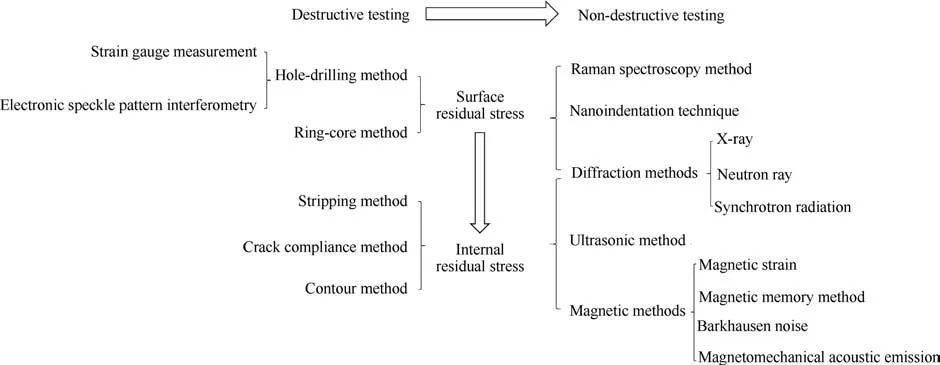
Fig. 1 Classification of residual stress measurement methods.
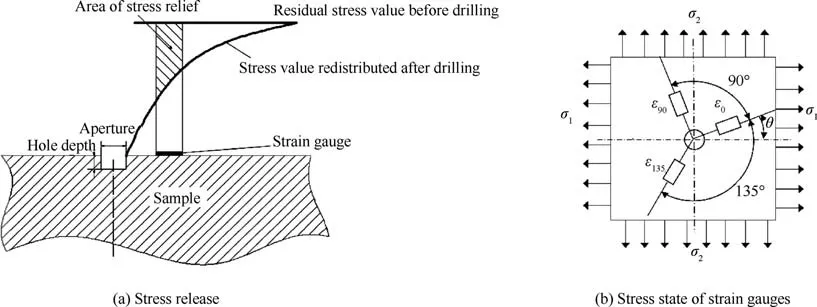
Fig. 2 Schematic diagram of strain gauge hole-drilling method.

In Eqs. (1)and(2), ε,ε0,ε90,and ε135are the radial strains;σ1and σ2are the principal stresses;and θ is the angle between the 0° strain gauge and the first principal stress direction.
The hole-drilling method is one of the most common surface residual stress testing methods. Mathar proposed the method and used it to measure several beams. The maximum relative error of the measurement results was approximately 10%. Then, a counterproof method for estimating deformation by cutting a beam with a known stress was presented.The error of the result was 7.4%, which proved the reliability of the method.2In different cases, the appropriate holeopening methods and parameters should be selected according to the different workpiece materials to achieve the highest accuracy possible. The hole-opening methods can be divided into the drilling opening method, sand blasting method and high-speed turbine milling hole method. The test depth of the hole-drilling method is generally 1.2 times the hole diameter.8The current research is mainly focused on improving the accuracy of the calibration coefficients A and B and improving their practicality.Gan et al.analyzed the elastic modulus error,strain gauge paste error and strain reading time error, as shown in Fig. 3, during the measurement of residual stress in the hole-drilling method and established the final error chain,which provides a reference for improving measurement accuracy.7
In recent years, with the rapid development of finite element approaches, studies have introduced the finite element method (FEM) for the calibration of the release coefficient,which simplifies the complexity and difficulty of calibrating it.In the past five years,a great deal of research work has been done to improve the accuracy of the calibration coefficient of the finite element method. Steinzig et al. considered the influence of the drilling parameters on the measurement accuracy.Through multiple sets of experiments, it was concluded that when the drill speed was lower than 10 kr/min or higher than 40 kr/min, the feed rate was 0.05 mm/s and a double-slot end milling cutter was used,the results were the most accurate,and the drills should be used less than 15 times.9Blo¨dorn et al.considered the real situation of a hole with a chamfer or rounded corner, as shown in Fig. 4, when drilling with an end milling cutter for a blind-hole method. Using the finite element simulation approach, the difference between the standard coefficient and the standard list can reach 50%.10In terms of the application scope of the drilling method, Magnier et al.considered the thermal and viscoelastic deformation of a polycarbonate material during drilling, successfully applied the residual stress of the hole-drilling method to the material,and performed a reliability analysis. The results showed that the accuracy was approximately 1–1.5 MPa at depths of 0.1–0.2 mm and approximately 0.5 MPa at depths of 0.2–0.7 mm.11Smit and Reid considered the different characteristics of each layer of composite materials and their mutual influence, which provides a reference for solving the problem of determining the residual stress distribution in composite laminates with an arbitrary structure.12
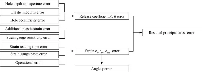
Fig. 3 Error chain in hole-drilling method.7
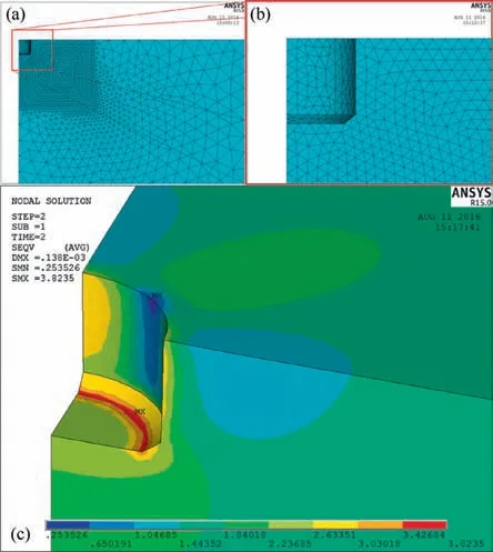
Fig.4 Stress nephogram of the real situation during drilling by a FEM simulation.10
At present, the equipment made for this method is very common. Advanced instruments, such as the MTS3000-Restan stress measuring instrument produced by SINT Technology in Italy,can conduct residual stress measurements with a maximum depth of 2 mm. The accuracy of the strain gauge hole-drilling method is affected not only by the errors in the calibration coefficients A and B but also by the sticking quality of the strain gauge, the eccentricity error of the strain gauge and the drilling center. To reduce the operational error in the measurement, noncontact measurements combined with the hole-drilling method have developed rapidly,such as ESPI.The residual stress analyzer produced by the Stresstech Company in Finland that uses this principle is a relatively accurate and reliable residual stress measuring device. Although the hole-drilling method is widely used, the sensitivity of the release strain is lower than that of other mechanical methods,such as the ring-core method, so the method is relatively unsuitable for low-level residual stress measurements; there are also other shortcomings, such as a small measurement depth, which restrict the application of the method.
2.1.2. Ring-core method
The basic principle of the ring-core method is similar to that of the hole-drilling method, which is a stress release method. A ring groove with diameter D is machined in the measured area by a crown milling cutter, which releases the residual stress in the ring core. A schematic is shown in Fig. 5. A special strain gauge rosette is pasted in the middle of the ring-core region,and the residual stress in the region is calculated using the same formula as the hole-drilling method.13From the perspective of the strain release, the ring-core method has a large strain release when the diameter D of the annular groove is small,and approximately 90%of the residual stress is released when the inner diameter D of the ring is 5.6 mm,which represents a higher sensitivity than that of the hole-drilling method.13Thus, the influence of errors during the data acquisition process is reduced,resulting in the accuracy and reliability of the method being usually higher than those of the holedrilling method. Ideally, when the workpiece material is steel,the accuracy can reach ±15 MPa.14
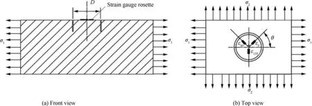
Fig. 5 Ring-core measurement schematics.
With the development of processing technologies, a variety of methods for processing ring grooves have been developed.For example, the resolution of electrical discharge machining(EDM) is higher than that of the traditional mechanical milling method, which improves the measurement accuracy.As one of the most important factors affecting the accuracy,the calibration coefficients have progressed in the past five years, both in terms of their accuracy and the application of different materials. In a study of improving the accuracy and application range, Chen et al. considered the influence of Poisson’s ratio on the strain release factor, used the finite element method to calibrate the strain release factor and established a modified formula considering Poisson’s ratio, as shown in Fig. 6. The relative error between the residual stress value obtained by this method and the actual value was less than 1%.15Moharrami et al. considered the influence of the plasticity effect,proposed a correction program for evaluating high-level residual stress in steel by the ring-core method, and obtained the residual stress with an error less than 1.5%.16Ghaedamini and Sadri measured the residual stresses of composites by the ring-core method, incremental drilling-hole method and slitting method. A comparison of the results shows that the strain release of the ring-core method is approximately 17%higher than that of the hole-drilling method.The results are shown in Fig. 7, which proves that the ring-core method is an accurate and stable method of measuring the residual stress in composites.17
At present, because of the requirements for the equipment and strain gauges, the application of the ring-core method is limited, but its advantages are outstanding. For example,residual stress over a wide depth range can be measured with a higher accuracy in theory than that of the hole-drilling method.The MTS3000-RingCore stress measuring instrument manufactured by SINT Technology has a sensitivity that is 3–4 times higher than that of the hole-drilling method and can measure residual stress at a maximum depth of 5 mm.As with the hole-drilling method, the method introduces additional errors due to the special strain gauge rosette used, so the noncontact measurement method has broad development prospects. The calibration of the stress release coefficients changed from the original tension test to the present finite element method, which is very rapid and convenient. The error between the current finite element method and the tension test method is approximately ±2%, but the improvement of the accuracy of the calibration coefficient in the finite element method still needs to be further studied.
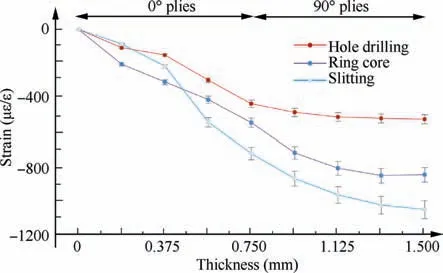
Fig. 7 Comparison of released strains in the longitudinal direction of laminated composites by different measurement methods.17
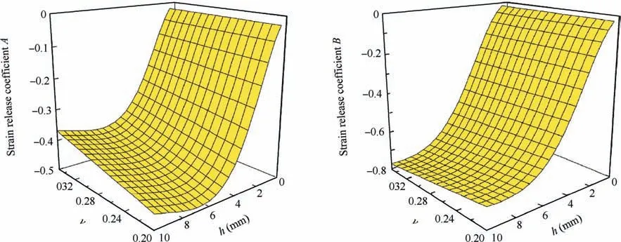
Fig. 6 Release coefficients A and B vs Poisson’s ratio and groove depth.15
2.2. New measurement method of surface residual stress:Electronic speckle pattern interferometry hole-drilling method
As mentioned above, the conventional drilling-hole method and the ring-core method use strain gauges to measure strain,but there are problems because the strain gauge itself affects the measurement accuracy. Therefore, to improve the measurement system, the use of laser speckle interferometry instead of traditional strain gauges to measure the strain released with the mechanical method is a hot research topic.ESPI has been in development for more than 40 years (see Fig. 8). In the 1970s, this technology was first applied to measure residual stress.With the rapid development of computers,charged-coupled device (CCD) cameras, image acquisition cards and lasers, ESPI technology has gradually matured.The method uses light as the measurement medium to conduct the noncontact measurement of workpiece strain based on a speckle interferogram.It has the advantages of high precision,fast and real-time online detection and has become an important means of modern mechanical testing.
In this method, the laser emitter emits a single coherent beam that is split into two beams by a beam splitter, where one beam of light illuminates the surface of the workpiece;the diffusely reflected illumination information is collected in the viewing direction, and a speckle pattern is formed on the lens. The other reference beam is passed through a computer,where the piezoelectric ceramic transducer(PZT)phase shifter is controlled, and a four-phase shift method is used to obtain coherent reference light of a known phase, which is also incident on the lens through the optical fiber. The computer analyzes the information collected by the CCD image sensor to obtain the phase difference before and after the deformation and determines the strain condition.18
ESPI is a new optical measurement technique that involves a displacement measurement. The research group headed by Wang at Hefei University of Technology has performed many studies of displacement measurements using digital electronic speckle interferometry, especially for three-dimensional displacement measurements using this method.The measurement system with three lasers as the light source developed by the research group has demonstrated the synchronous measurement of a three-dimensional dynamic deformation of a workpiece. The system and the speckle interferometry system Q300 by the Dantec Company demonstrated the synchronization deformation test with an aluminum plate, and the results in the three directions were similar and had a maximum error of 17.98%.19–21Since the ESPI method is a new measurement method, its accuracy is constantly being improved, and new measurement ideas are consistently proposed for residual stress measurements. Steinzig and Ponslet described the technology principle and algorithm and developed related equipment based on the number collected by the global least squares analysis. They then used a 2024-T351 aluminum ring with a thickness of 12 mm and a diameter of 100 mm to verify the accuracy and reliability of the equipment system.Four sets of data for the same sample were obtained that had a maximum standard deviation of 20.1 MPa.22–24Hizliet and Gu¨r used ESPI and XRD methods, respectively, to measure the residual stress of heat-treated steel, and it was concluded that there was little difference between the two methods because they were within 0.8 mm of each other, as shown in Fig. 9.25Pisarev et al.developed a measurement system for a combined interferometer that combined electronic speckle interferometry with reflection holographic interferometry, as shown in Fig. 10. The error of the device in practice is within 3%.26
ESPI,a noncontact method combined with the hole-drilling method to measure residual stress, and it provides a new research approach for residual stress measurement. In terms of equipment, Stresstech Company is a leading company in this field. ESPI measurements of residual stress improve the accuracy and reduce the error caused by the additional factor of the strain gauges. Nevertheless, it is still affected by the error of the hole-drilling method itself, such as the drill bit,and illumination information, such as the laser intensity and stability. The key way to improve the accuracy is to improve the credibility of the illumination information,speckle pattern and algorithms,which are embodied in the data collection and processing steps.
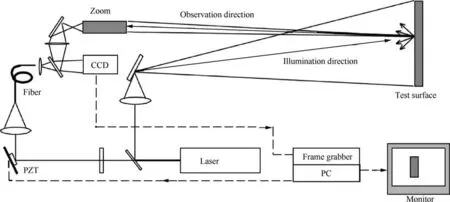
Fig. 8 Typical ESPI system layout.18
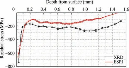
Fig.9 Comparison of the residual stress depth profiles obtained by ESPI-assisted hole-drilling and XRD methods (for a sample carburized-tempered at 180°C).25
2.3. Traditional measurement methods of internal residual stress: Stripping method
Assuming that the residual stress is uniformly distributed in each layer of a workpiece, when a layer with a residual stress is peeled off,the residual stress is released,resulting in redistribution of the stress,which causes bending and deformation of the workpiece, as shown in Fig. 11. Based on the theory of elasticity, Eqs. (3) and (4) for the relationship between the depth and deformation are deduced.27According to the measured results, the initial residual stresses of the specimens are obtained.

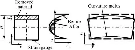
Fig. 11 Schematic diagram of the stripping method.28

In Eqs. (3) and (4), εxand εyand σxand σyare strains and stresses in the x-axis and y-axis directions,respectively;t is the depth of each layer that is removed; H is the workpiece thickness; and E′is the relationship between the elasticity modulus and Poisson’s ratio.
In current studies of the stripping method, a processing stress is introduced on the machined surface during milling(stripping), which affects the strain results. Milling and electrolysis are the two main stripping methods. In the past five years, progress has been made regarding the introduction of a stress correction and optimization of related processing parameters. A low compressive stress is introduced by the high-speed processing method of vertical milling, so to reduce the error caused by the introduction of a stress and improve the measurement accuracy, Wang and Liao proposed a calculation method for an improved stripping method. The sample plane size should be 2–3 times its thickness to ensure the stability of the results.27–30Huang and Li deduced a revised formula for calculating three-dimensional residual stresses considering that the measurement error of the residual stresses accumulate gradually with the stripping depth, and they verified this approach with 35CrMo steel.The results showed that the deviation between the axial stress and uncorrected stress can reach 971%,as shown in Fig.12,which proved the importance of the correction.31The stripping method of electrochemical milling does not introduce a residual stress, so stripping is suitable with this method; however, the low electrolytic efficiency increases the measurement time and cannot be used for nonelectrolytic materials. Dong et al. carried out step-type stripping experiments on a 18CrNiMo7-6 gear steel to determine the relevant stripping parameters, such as the current density,and proposed a step-like stripping method, which can repeatedly measure the residual stress of any layer and improve the measurement efficiency.32
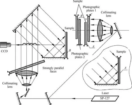
Fig. 10 The optical system comprising an interferometer apparatus.26
Stripping is one of the most well-known methods for measuring the residual stress inside a workpiece. The accuracy of the traditional strain gauge method for measuring the internal residual stress is generally 30–50 MPa because of the influence of the strain gauge itself. Presently, when it is combined with XRD measurements, the stripping method is mostly used to obtain the internal residual stress. The most important factor affecting the accuracy of the stripping method is the uniformity and controllability of the removed material. It is very important to select appropriate removal methods for different materials and to optimize the process parameters. During stripping, it is necessary to consider both the introduction and reduction of the stress,so further research on this method still needs to be carried out.
2.4. Expansion of internal residual stress measurement methods
2.4.1. Crack compliance method
In 1971, Vaidyanathan and Finnie first proposed the crack compliance method. They used the photoelastic coating method to measure the stress intensity factors at different depths of the crack and then calculated the residual stress.They used the method to measure the residual stress distribution of an electron beam welded aluminum sheet. Compared with the results measured by a strain gauge,the maximum relative error was 21.3%.The trend was consistent,which proved the feasibility of using a stress factor to measure a residual stress.33This method has the advantages of simple operation and low cost and is suitable for the measurement of the internal residual stress distribution in a metal with a simple structure and low stress amplitude. Since the method is extremely sensitive to the strain perpendicular to the direction of the crack, the measurement accuracy of the method is generally higher than that of the hole-drilling method and the stripping method.
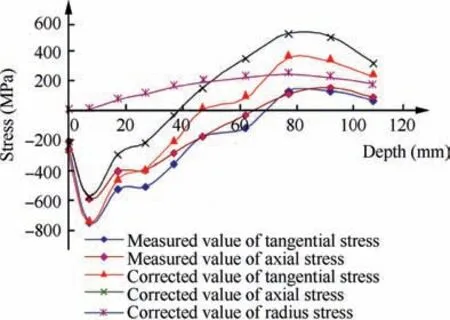
Fig. 12 Comparison of residual stress distribution in a 35CrMo steel sample measured by the corrected and uncorrected stripping methods.31
The crack compliance method is based on the principle of linear elastic fracture mechanics.A crack with increasing depth is introduced on the surface of the measured object to release the residual stress σx, which can be expressed as a spreading series along the crack direction, like in Eq. (5). A schematic diagram of the process is shown in Fig. 13.

In Eq. (5), Aiis the undetermined coefficient and Piis an interpolation function.
Then, by measuring strain ε corresponding to different crack depths, the flexibility function C is obtained by Eq. (6):

Therefore, the undetermined coefficient matrix A is obtained according to Eq. (7), and finally, the value of the residual stress along the depth distribution is obtained.34

The crack compliance method is a new technology, and cracks are not easy to control in actual operation. Therefore,a narrow groove is used to replace the crack by milling and EDM. When the ratio of the depth to the width of narrow grooves is more than 5, the results obtained by replacing cracks with narrow grooves were basically the same.35This method is very suitable for the residual stress measurement of aluminum alloy prestretched plates. Gadallah et al. proposed a finite element method to evaluate the stress intensity factors of cracks in the welding residual stress field, studied the influence of the crack angle and other factors on stress intensity factors, and provided a new approach for the evaluation of residual stresses by the crack flexibility method.36In the application range, Chen et al. used the crack compliance method and increased the length and depth of the introduced crack simultaneously, so an incremental crack compliance method was proposed to obtain the two-dimensional distributed residual stress field in the cross section of the workpiece. The measurement schematic diagram is shown in Fig. 14(a). A comparison of the results obtained by the simulation and the given residual stress field showed that the relative error of most regions was less than 5%, as shown in Fig. 14(b), which extends the application range of the crack compliance method.37Since the measurement accuracy of the method is sensitive to the size of the workpiece, Gong et al.studied the error source of the stress calculation method by the crack compliance method in this study. By sampling and analyzing workpieces with different thicknesses, it was concluded that when the sampling length is greater than 2.67 times the thickness and the width is greater than 2 times the thickness,the error caused by cutting was less than 5%,which can ensure the accuracy of measurement results.38Olson and Hill used numerical analysis to evaluate the influence of other factors,such as the length–width ratio and cutting depth of the specimen, on the measurement accuracy. Finally, an experimental verification was carried out using a quenched 7050 aluminum alloy plate with a thickness of 5 mm. The results showed that when the aspect ratio was less than 1.5, the measurement results in the middle of the specimen were optimal, and the accuracy increased when the cutting depth was greater than 1/5 of the width; in addition, the results differed from those obtained with the X-ray diffraction and ESPI hole-drilling methods by 10–20 MPa.39In addition, the measurement accuracy was also affected by the selection of the interpolation function and its order and the calculation method of the crack compliance function. In terms of measurement methods, Pisarev et al. used ESPI to obtain local deformation caused by cracks and obtained a crack intensity factor, which provided a new approach for measuring residual stress by the crack compliance method.40

Fig. 13 Schematic diagram of the crack compliance method.34
2.4.2. Contour method
The crack compliance method has the disadvantage that the size effect affects the accuracy,which provides an opportunity for the development of the contour method.As a new method for measuring residual stress, the contour method was first proposed by Prime and Gonzales at the 6th International Conference on Residual Stress in 2000.They carried out validation experiments on steel parts with known stresses,and the results were similar to the actual values,which confirmed the feasibility of the method.41After more than ten years of development,the contour method is currently being applied in the field of welding residual stress testing and is a damage detection technology with high test accuracy.
The workpiece with residual stress is cut along the section where the residual stress needs to be measured. A schematic diagram is shown in Fig.15.It is assumed that the cutting surface is an ideal plane and that there is an unknown residual stress σAin the sample. Due to the stress release and redistribution, the contour of the cutting surface is deformed, and an external reverse stress σCis applied to the interface to restore the deformed cutting surface to the plane state before cutting. Based on Bueckner’s superposition principle,42the applied external reverse stress is the residual stress. In actual operation, to ensure the ideal plane assumption of the cutting surface and reduce the error,the position of the required measurement is generally processed by wire-cut machining with low processing stress. Then, the profile data are collected and fitted by measuring devices, such as a three-coordinate or laser displacement sensor. The profile is loaded into the stress-free finite element model in the opposite direction, and the stress distribution of the section is finally obtained.
The stripping method is not suitable for measuring welding parts with a sharp variation of internal residual stress,and this problem is solved with the contour method.43However, only residual stresses perpendicular to the cross section can be measured for a single cut. The measurement accuracy is mainly related to the methods of collecting and fitting the contour data and the processing of the cutting surface, and the error caused by shear stress must be considered and corrected.Fig. 16 shows one of the methods used to correct the error caused by shear stress.44
The accuracy of the contour directly affects the accuracy of the measurement results, so the method of acquiring the contour and the data processing have been the focus of studies.In the past five years,Li et al.used the contour method to measure the residual stress of an aluminum alloy T-plate after quenching and adopted envelope processing, contour averaging, and cubic spline interpolation processing to measure the contour, which effectively reduced the error.45Toparli et al.proposed a new criterion for determining the optimal smoothing parameters based on spline smoothing analysis of the contour data. It was concluded that cubic spline fitting could obtain additional details, and a second-order finite element type should be used to measure residual stress near the surface,as shown in Fig.17.46Sun et al.considered the cutting-induced plasticity error, which indicated that the cutting direction and the clamping condition affect the accuracy of the result by affecting the degree of plastic deformation and proved that the closer the clamping position is to the cutting plane, the smaller the measurement error.47Olson et al.considered other factors, such as displacement noise and surface smoothing errors in the measurement profile, and established a method to determine the uncertainty of the contour method. It was concluded that the contribution of the model error to the uncertainty was much larger than the error of the displacement, as shown in Fig. 18; it was also experimentally shown that the uncertainty was relatively constant in the interior and increased along the boundaries.48,49

Fig. 14 Incremental crack compliance method and relative error distribution of residual stress results.37
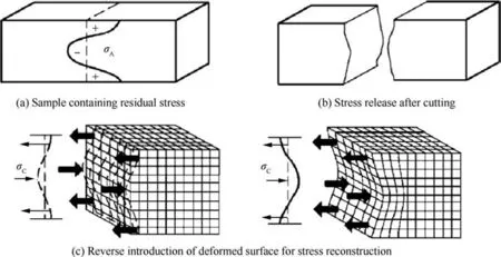
Fig. 15 Schematic diagram of the contour method.
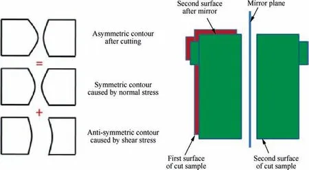
Fig. 16 Diagram of cutting surface deformation and average data correction.44
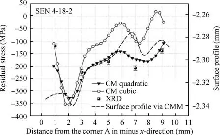
Fig. 17 Contour fitting method and residual stress results of laser-peened aluminum alloy specimens.46
The contour method can be used to measure the internal residual stress of a workpiece with a large thickness and is not limited by size. The measurement accuracy is related to the accuracy of the surface displacement signal acquisition device and can generally reach±20 MPa at the present time.50Because of the influence of cutting factors,the results of residual stress measurements near the surface have a large error,and improving the cutting method and contour acquisition method would improve the accuracy. The key points of its research are as follows. (1) Cutting methods are important for reducing the amount of introduced stress and improving cutting accuracy, and (2) improving the resolution and other factors improves the contour measurement accuracy and establishing appropriate fitting methods also reduces contour error. In recent years, to overcome the shortcoming that the residual stress near the surface measured with the contour method has a large error, a comprehensive method that includes methods that can measure the surface stress has become a hot research topic. Xie et al. combined the contour method with the X-ray diffraction method to measure the internal and surface residual stresses of welded components with a large thickness and obtained a high-precision residual stress distribution.51
3. Nondestructive testing
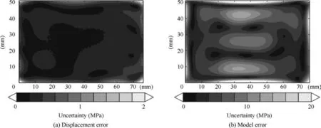
Fig. 18 Uncertainty of residual stress measured on a quenched aluminum rod by the contour method.48
Nondestructive testing methods,that is,physical testing methods, mainly measure the residual stress based on the physical properties of the material. In some cases, to avoid affecting the continued use of the workpiece, destructive testing methods are unacceptable. Nondestructive testing technology is an indispensable and effective tool and has experienced expanded adoption and become the main residual stress measurement method for the future.Classical methods of measuring residual stresses were first developed by means of acoustic and optical physics,which laid a foundation for nondestructive testing of residual stresses. With the development of ultraprecision machining and micromachining technologies, residual stress measurement technologies for microstructures have gradually developed and expanded the application scope of nondestructive residual stress testing. In view of the low measurement efficiency and complicated processes associated with nondestructive testing methods, new and efficient measurement methods have been proposed and developed rapidly.Although some nondestructive testing methods are not perfect in theory due to a short development time, their real-time dynamic advantages endow them with potential for future development.
3.1. Classical measurement methods
3.1.1. Diffraction method
The diffraction method is the most widely used and mature technology among nondestructive testing methods and includes X-ray diffraction (XRD), neutron diffraction and X-ray synchrotron radiation. In the early 20th century, Xrays began to be used to determine the stress of crystals. In 1961,Mchearauch proposed the sin2ψ method for X-ray stress measurement. Currently, XRD is the most widely used stress measurement method and has been applied in various measurement fields.
When there is residual stress in the sample, the interplanar spacing d will change, as shown in Fig. 19. The diffraction peak moves when Bragg diffraction occurs,and the magnitude of the movement is related to the stress. X-rays with wavelength λ are irradiated onto the sample at different incident angles. According to the Bragg Eq. (8), the relationship between the diffraction angles 2φ and the corresponding d is obtained,where n is the order of the reflection.When different incident angles are irradiated on the sample,the slope M of the diffraction angle to sin2ψ can be obtained. According to the theory of elasticity, the residual stress in the corresponding direction can be obtained by Eq. (9):52

In Eqs. (8) and (9), K is the stress constant and ψ is the angle between the normal of the sample surface and the normal of the diffractive crystal surface.
The X-ray diffraction method is widely used in nondestructive testing in the laboratory due to its high accuracy. The method requires that the grain size of the workpiece should not exceed 100 μm, and the result is better at 30 μm. It has been applied to the residual stress measurement of ceramic materials, bent thin film surfaces and spherical surfaces, and the feasibility of the method has been proven.53,54However,the measurement depth is only approximately 10–30 μm.Although X-ray synchrotron radiation and neutron diffraction can solve this problem and can measure residual stresses at great depths, the relevant testing equipment is very scarce,which limits their practical application. Measuring equipment based on the XRD principle has developed rapidly, such as RS-2016 stress measuring equipment produced by the Stresstech Company, which can realize three-dimensional stress measurements. The iXRD residual stress meter manufactured by the PROTO Company in Canada can measure the residual stress with an accuracy of ±8 MPa. Table 1 summarizes the accuracy of diffraction methods.
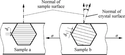
Fig. 19 Schematic diagram of spacing between crystal planes varying with stress.
Diffraction is a classical stress measurement method,but its measurement accuracy is constantly improving.In the past five years, the factors affecting accuracy have been studied in detail, and progress has been made in the development of new measurement approaches. Rae et al. used a variety of techniques to measure the residual stress of electron beam welded Ti-6Al-4V, and the results were consistent, which proved the feasibility of the method.56Suzuki proposed a new method to obtain residual stress by measuring the diffraction angle of X-rays with an area detector,which extended the application range of residual stress measurement by X-ray diffraction.57To determine the position of the diffraction peak,Luo and Jones measured it using the maximum intensity(Imax) method, the middle point of half maximum (MPHM)intensity method,the gravity center method,and the parabolic approaching method. The linear regression precision coefficient (R2) for sin2ψ and 2θ was used as the evaluation index for the accuracy. Various materials were measured, and the results showed that the diffraction peaks located by the parabolic approximation method had the highest accuracy among the methods that were considered, as shown in Fig. 20.58
3.1.2. Ultrasonic method
Based on the theory of acoustic elasticity,this method uses the phenomenon of acoustic birefringence in a stressed material,that is, the propagation velocity of an ultrasonic wave in an isotropic elastic body is affected by the stress and its magnitude,and the relationship between the ultrasonic wave velocity and the stress is used to measure the residual stress. When an incident ultrasonic shear wave is normal to the surface of an anisotropic solid, it can be divided into a quasi-longitudinal wave and two quasi-transverse waves. However, if the ultrasonic shear wave propagates along the main axis of symmetry of the anisotropic medium, then the relationship between the ultrasonic polarized shear wave (Eq. (10)), the longitudinal wave (Eq. (11)) and principal stress can be derived from the theory of finite deformation elasticity.59

In Eqs.(10)and(11),V0and Vi0are ultrasonic wave propagation velocities in an isotropic elastomer without stress; V1,V2and Viare the components of the wave propagation velocity in the direction of the principal stresses in the stressed workpiece; and S is the stress acoustic constant.
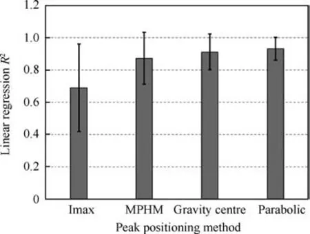
Fig. 20 Comparison of the values of the linear regression precision factor following the four diffraction peak positioning methods.58
The types of ultrasonic measurements include the following59: 1) a direct measurement of the pulse propagation time,which is the most widely used application; 2) the phase comparison method; 3) the sing-around method, which is mainly used in the determination of welding residual stress;4)the echo amplitude method,which has a simple operation and a certain precision; 5) the ultrasonic goniometer method, which is applied often for the measurement of residual stress on the surface of tooth blanks; 6) spectral methods; and 7) tomography methods. The measurement range of the method is related to the yield strength of the material to be tested,and the measurement range and stress sensitivity of a workpiece using shear transverse waves and longitudinal waves are also different.60At present, the accuracy of general equipment for residual stress measurement by this method can reach approximately±30 MPa,and the reliability is generally 95%within 5000 repetitions.The USM-3 ultrasonic bolt stress tester manufactured by the Norbar Company has a high degree of automation and can measure 5–500 mm length workpieces.The research group led by Xu at the Beijing Institute of Technology has completed many studies on ultrasonic residual stress detection technology to improve its measurement accuracy, including sorting ultrasonic waves according to the sensitivity of the different types of ultrasonic waves and studying the calibration technology of the ultrasonic residual stress measurement so that the actual accuracy of the system, in theory, is within 10 MPa after calibration. For the stress detection of the thickness gradient of the workpiece, they designed an apparatus consisting of oblique incidence probes,where one sends and one receives the signal. The device is shown in Fig. 21, which can obtain the residual stress of different depths by changing the frequencies of ultrasonic waves.61–65
At present, many scholars have performed research on model corrections and optimization of measurement algorithms. Temperature has been proven to be an important factor that affects the velocity of ultrasonic waves.66Liu et al.considered the influence of temperature and the couplingcondition between the probe and measurement surface and improved the conventional single-transmitter-single-receiver detection configuration into a single-transmitter-double receiver configuration. A schematic of the system is shown in Fig. 22. The experimental results for a prestretched aluminum alloy with uniaxial stress were compared with the simulation results, and the measurement accuracy of the method can reach 20 MPa.67

Table 1 Accuracy of diffraction method.55
Owing to the low sensitivity of sound velocity to stress in a workpiece, a stress at the MPa level usually only causes a change in sound velocity at the nanosecond level, and the texture of the material causes a fluctuation in sound velocity during the measuring process, which makes the accuracy of the ultrasonic method greatly affected by the environment.Therefore, the influence of several factors, such as the microstructure, composition and surface roughness of a material, are also considered by scholars.68,69In a new measurement method, Lu et al. used a high-precision ultrasonic microscope measurement system and a two-dimensional scanning method to determine the residual stress distribution of welded components by measuring the surface wave velocity of the heataffected zone at different locations in the components, which represented a new approach for the measurement of residual stress. A schematic diagram of the system is shown in Fig. 23.70Chen et al. proposed a method for measuring the propagation time of ultrasonic signals based on the phasefrequency relationship,which improved the resolution and stability of the measurement.71Joshi and Walton developed a nonlinear inverse spectral technique to reconstruct the residual stress of the hyperelastic body by an ultrasonic method,which extended the application scope of the ultrasonic method.72
3.2. Measurement method suitable for microstructures: Raman spectroscopy method
Raman spectroscopy,which is based on the Raman effect discovered by Indian scientist Raman in 1928, is an analytical method applied to the study of molecular structures. When light scattering occurs, the frequency or wavenumber of the scattered light may change, where a change in the frequency is greater than 3×10¹⁰Hz, and a change in the wavenumber is greater than 1 cm-1, which is Raman scattering.73When a material is subjected to stress,its lattice structure changes;that is, when it experiences compressive stress, the bond length of the molecule decreases. According to the relationship between the force and the bond length,the force constant increases,and the vibration frequency increases.In the Raman spectrum,the band shifts to a high frequency,which is called a Raman shift,as shown in Fig. 24. According to the proportional relationship between the stress and the relative Raman frequency shift in Eq. (12), the stress in the crystal can be calculated accurately:74

Fig.21 Principle of stress gradient testing and the relationship between the penetration depth and the frequency in measuring Q235 steel by LCR wave.62
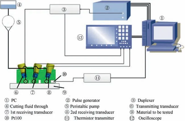
Fig. 22 The single-transmitter-double-receiver ultrasonic stress measurement system.67
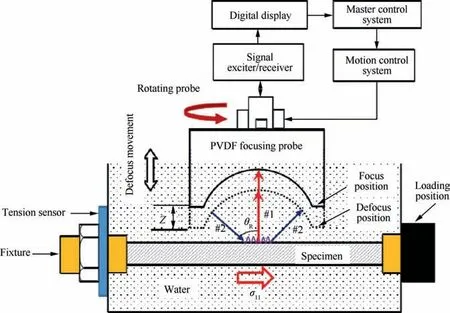
Fig. 23 Schematic of the defocusing measurement system for SAW velocities.70

In Eq.(12), φ is the stress constant,which can be obtained by calibration experiments, and Δγ is the frequency variation.The Raman spectroscopy method has proven to be a suitable method for measuring nonuniform residual stresses in microstructures.75,76The measurement accuracy is affected by many factors. First, Raman scattering of light only accounts for a small portion of the scattering, and Rayleigh scattering interferes with the Raman scattering, which is one of the main sources of error.In addition,the Raman frequency shift is affected by external factors, such as focusing depth,laser thermal effects, room temperature, and stability of the CCD. In the application of different materials, Qiu et al.deduced the Raman-mechanical measurement correction relationship for multilayer semiconductor heterostructures and carried out micro-Raman mechanical measurement experiments on the surface and cross-section of a sample, and the residual stress distribution inside the structure was given as shown in Fig. 25.77Huang et al. measured SiCf/C/Ti17 composites by Raman spectroscopy and XRD. The difference between the measured results was within 55 MPa, which indicates the feasibility of the Raman spectroscopy method.78Gigler et al. measured the residual stresses of SiC crystals caused by nanoindentation using an infrared (IR) scattering-type scanning near-field optical microscopy (s-SNOM) and confocal Raman microscopy. The results in Fig. 26 show that the distribution of the residual stresses in the SiC crystals was similar and proved the feasibility of the Raman spectroscopy method. The difference might be due to the different measuring depths of the two methods.79Qiu et al. considered the different stress factors of silicon crystals on different crystal planes, established a general model of stress factors for arbitrary crystal planes,and obtained the residual stress in the corresponding direction.80
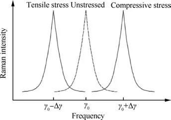
Fig. 24 Raman frequency shift phenomenon.
The Raman spectroscopy method has the advantages of nondestructive and nonuniform residual stress measurement capabilities. Since the 1960s, with the rapid development of laser technology and nanotechnology, Raman spectroscopy has gradually matured and there is great potential for its continued development and application.The inVia reflex confocal micro-Raman spectrometer produced by the Renishaw Company, UK, has a transverse resolution of less than 0.5 μm and an optical axis resolution of less than 2 μm. It is widely used in laboratory measurements. However, since its accuracy is highly susceptible to external conditions, it is particularly important to study effective methods for coefficient calibration and how to remove noise from the collected experimental signals. The key point is the effectiveness and stability of the denoising fitting function. Current denoising methods have their own advantages and disadvantages, so further research is still needed.
3.3. Efficient new measurement methods
3.3.1. Nanoindentation technique
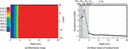
Fig. 25 Residual stress on the cross-section sample.77
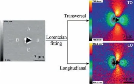
Fig. 26 Confocal Raman microscopy of a locally stressed SiC sample.79
Load-displacement curves that are obtained during nanoindentation testing are shown in Fig.27.According to the curve,not only the performance information can be obtained,such as material hardness and elastic modulus, but also the residual stress can be measured. The research on residual stress measurement by the indentation method originated with the traditional Rockwell hardness test and Vickers hardness test. As a newly developed technique for measuring residual stress,it has advantages of being nondestructive, fast, and able to test the mechanical properties of materials in a very small range;thus,it has been studied by many scholars.
In nanoindentation experiments, the hardness and elastic modulus of materials are not very affected by residual stress,but the contact area is very sensitive to residual stress.81According to the theory that is based on Hertz contact theory in contact elastic mechanics, the residual stress state can be evaluated by the classical mechanics method, strain gradient plasticity theory and molecular dynamics simulation.
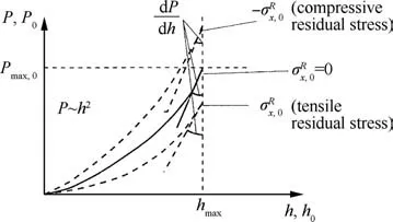
Fig. 27 Variation of the load–displacement curve on the material surface caused by residual stress.83
With the development of indentation measurement technology, there are several typical models for measuring residual stress.82
1) Models suitable for sharp indenters
(1) The Suresh theoretical model. Assuming that the residual stress σRis equiaxial and uniform, when a residual tensile stress exists in a workpiece,the residual stress can be obtained by a fixed load and a fixed indentation depth,such as Eqs.(13)and (14)83:

When a residual compressive stress exists in the workpiece,Eqs. (15) and (16) are adopted:

In the equations, H is the hardness of the material; α is the angle between the surface of the conical indenter and the surface of the material; h and h0are the indentation depth of materials with and without residual stress, respectively; and A and A0are the surface indentation areas of materials with or without residual stress, respectively.
Regarding defects, a sample in the calculation model that contains no residual stress is used as a reference,but reference parts are difficult to obtain. This calculation formula is not suitable for the calculation of residual stress in very soft materials.84Zhang et al. used the theoretical model to measure the residual stress of unannealed stainless steel, which was 381 MPa. Moreover, XRD was used to measure the residual stress in the stainless steel, and the result was 350±23 MPa,which proved the feasibility and accuracy of the model in measuring residual stress in stainless steel.85
(2)The Lee theoretical model.There are three models available for when the indentation depth is constant. Model I was established according to the slope of the loading curve with or without residual stress, like in Eq. (17), where Presis the load difference caused by residual stress. The biaxial residual stress is decomposed into a spherical stress tensor and partial tensor in model II. The plane stress is equivalent to an equibiaxial and a nonequibiaxial stress, a uniaxial stress and a pure shear stress in model III.

2) The Swadener theoretical model for spherical indenters.Swadener et al.applied a model to calculate the residual stress of an aluminum alloy using Hertz contact theory and the relationship between the hardness and yield strength, as in Eq.(18). The accuracy of the method was within the range of 10%-20% of the yield strength.86

where σyis the yield stress, Eris the modulus of elasticity, a is the radius of the contact area and R is the radius of the indenter.
3) The Xu theoretical model. Based on the relationship between the elastic restitution coefficient and the residual stress, a model was established, as shown in Eq. (19).87The method requires an accurate measurement of the elastic restitution coefficient. However, when the surface roughness of the workpiece is large, the error in the elastic restitution coefficient is large,which reduces the accuracy of the residual stress results.

In Eq. (19), he/hmaxis the elastic restitution coefficient,which can be measured experimentally, and β is the elastic restitution coefficient of the material without residual stress.
4)Energy method model.Based on the work performed by the residual stress during the indentation process, a model of the relationship between them was established. Jin et al. performed a large amount of research on the improvement of this method and proposed an improved method of calculating the equal biaxial residual stress by the energy method. Reverse analysis was performed on a material with a known stress,and the error between the output of the method and the known value was less than 9%.The results from this method was compared to those from the XRD measurement, and the results were consistent.88,89
Indentation methods have been used by many scholars to measure the residual stress of aluminum alloys and other materials.90,91At present,the combination of FEM and indentation methods has become a hot research topic. Hao et al. studied the effect of the dimensions on the indentation method by the finite element method and estimated the residual stresses corresponding to different indentation depths based on the Suresh model. When the results were compared with those of the residual stresses in given states,the reasonable indentation depths for the measurement of the biaxial tensile and compressive residual stresses in a 2A12 aluminum alloy were 0.65 mm and 0.45 mm, respectively, as shown in Fig. 28.92
Shen et al.considered that the indentation method can only measure residual stress in one direction at present and put forward a new indentation method for measuring residual stress based on a special correspondence between the pile-up deformation around an indentation after unloading and the residual stress, as shown in Fig. 29. The results of the residual stress measurement of a Q235 steel by XRD and the Shen method are compared and show that the trend is consistent and the maximum difference is less than 15 MPa.93To reduce the influence of the strain hardening index on residual stress, He et al.measured the residual stress of a 7050-T7452 aluminum alloy surface at several points by estimating the average contact stress with a typical stress. The results were compared with those from XRD. The trend was consistent, and the size was similar, which proved the accuracy of the method.94
The nanoindentation method has the advantages of being a nondestructive measurement method and having high measurement efficiency.Researchers have proposed various calculation models, but there are shortcomings that cause inconsistencies among the residual stress results obtained by different calculation models for different materials and different processing methods. Therefore, the accuracy and application scope of the model still needs to be further determined,or a complete calculation model should be established for different factors affecting the residual stress. In addition, the application of the finite element method has greatly promoted the development of the nanoindentation method.Based on the relationships among the indentation fracture technique, other factors(hardness,stiffness)and residual stress,the use of finite element models to calculate residual stress has become a new current research direction. However, due to the deviation between the boundary conditions of finite element simulation and the actual situation, some of the methods need to be improved.
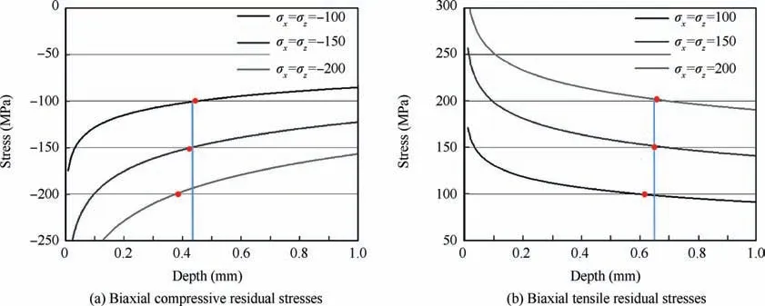
Fig. 28 Estimated and true values of residual stresses of 2A12 aluminum alloy at different depths.92
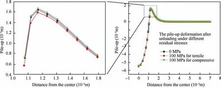
Fig. 29 Pile-up after unloading under different residual stresses.93
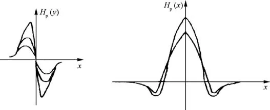
Fig. 30 Signal distribution of leakage magnetic field in the stress concentration region.
3.3.2. Magnetic method
1) Magnetic memory method
When a magnetized metal workpiece has an external load,a local magnetic signal anomaly in the stress concentration region may occur inside the material due to the irreversible change in the magnetization in the stress concentration zone and the discontinuity of the material in metal components,forming a‘‘leakage magnetic field”that remains after the load disappears.The tangential component of the leakage magnetic field signal Hp(y) has a maximum value, and the normal component Hp(y) changes the sign and crosses the zero point, as shown in Fig.30.The stress concentration region of the workpiece can be inferred from the variation of the measured magnetic signal curve and the gradient value of the corresponding magnetic signal.95
The magnetic memory method was first proposed by Doubov in 1994, and a substantial amount of research has been carried out since that time.96,97As the research progressed,technical standards were promulgated. The method is mainly aimed at the detection of stress concentrations, but the surrounding environment has a great influence on the accurate evaluation of weak magnetic signals. Therefore, the accuracy of this method and its position accuracy have been studied and need to be further improved.98–100The TSC-3M-12 stress concentration magnetic detector manufactured by the Energodiagnostika Company of Russia has 12 measuring channels, and magnetic field measurements with a relative error less than ±5% can be obtained in each channel. In recent years, many scholars have paid attention to the quantitative measurement of residual stress by the magnetic memory method and made progress.101,102Liu et al. established a magnetic memory detection model of the electron potential of a magnetic leakage signal based on the density functional theory in quantum mechanics and established a quantitative relationship between the magnetic memory signal and the stress concentration, which proved the feasibility of the method and provides a reference for the quantitative evaluation of stress.103
2) Magnetic strain method
The basic principle of the magnetic strain method is based on the magnetostrictive effect of ferromagnetic materials; that is, the size of ferromagnetic materials changes when magnetized. When the material is under stress, the permeability of the material changes accordingly. The relative change in the magnetic permeability is proportional to the stress, and the residual stress is determined by measuring the change in the total magnetic resistance in the magnetic circuit, that is, the measurement of the current amount, as in Eq. (20).104The working principle diagram is shown in Fig. 31.

In Eq. (20), I1and I2are the maximum current and the minimum current, respectively, and K′is the sensitivity coefficient.
In the existing magnetic strain algorithm, the principal strain of the magnetic strain method needs to be solved by means of boundary conditions. During actual measurements,it is difficult to determine the boundary conditions, and the cumulative error of the algorithm is large, which reduces the accuracy of the solution.The stress and magnetic permeability are approximately linear when the stress is less than 300 MPa and nonlinear when the stress continues to increase.Therefore,the magnetic strain method needs further deepened and improved for the direct measurement of high residual stress components.
3) Magnetic noise method and magnetomechanical acoustic emission method
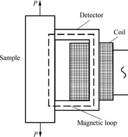
Fig. 31 Principle diagram of detector in magnetic strain method.104
The magnetic noise method is called Barkhausen noise(BN) technology. When a ferromagnetic material is magnetized, the magnetic domain rotates discontinuously. When a residual stress exists, a change in the permeability occurs so that a series of Barkhausen electric pulse signals are generated in the receiving coil on the surface of the test piece. When the external magnetic field is parallel to the stress,the BN signal is proportional to the tensile stress,inversely proportional to the compressive stress and related to the direction of the magnetic field and residual stress. When the magnetic probe rotates around the material surface, the maximum and minimum signals correspond to the two principal stresses. The magnitude of principal stress can be obtained by comparing the BN signal values for a material under stress and in a stress-free condition.The principle of magnetomechanical acoustic emission is similar to the magnetic noise method, which collects signals with piezoelectric crystals.105,106The detection system is shown in Fig. 32.107
In recent years, research on magnetic noise methods has increased, the regularity and characteristics of noise signals have deepened gradually, and progress has been made in new measurement approaches and the measurement of microstructures. The 3MA micromagnetic multiparameter stress analysis instrument produced by the Fraunhofer Institute in Germany integrates various magnetic measurement methods,such as BN and incremental permeability,to achieve nondestructive and rapid detection of residual stresses.Lasaosa et al. improved the Barkhausen noise model and developed a nonmonotonic residual stress measurement method for profiles with different shapes and depths. The residual stress distribution results of a low carbon steel with depths of 130 μm and errors less than 70 MPa were obtained with this method.108The research on expanding the microstructures that can be measured is one of the important factors affecting the accuracy of magnetic measurements.Hizli et al.compared the results of residual stress measurements of a 19CrNi5H steel at different carburizing times and tempering temperatures using the BN method and XRD method. It was concluded that the BN method could not directly measure carburized specimens.109Vourna et al. used the BN method,magnetic strain method and XRD method to measure the residual stress of a welded electrical steel. It was found that the results of the magnetic strain method were not consistent with those of the other two methods. The reason was the change in the microstructure that occurred during welding.110Therefore,the magnetic method should be calibrated in places where the microstructures are obviously different.
At present,the magnetic method is still in the primary stage of development, and each theory is not sufficiently mature.The magnetic memory method can qualitatively evaluate stress concentration areas,but it has not yet formed a complete set of mature models and standards for quantitative residual stress detection.In terms of application,one of the major factors limiting its application scope is the influence of microorganization on the measurement accuracy.How to eliminate its influence is one of the key problems to be solved.On the other hand,considering the combination of other magnetic parameters, such as the coercivity, incremental permeability, and tangential magnetic field harmonic, further analysis of the impact of other properties on it should have a broad development prospect.
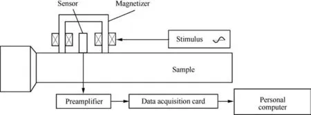
Fig. 32 BN and MAE detection system.107
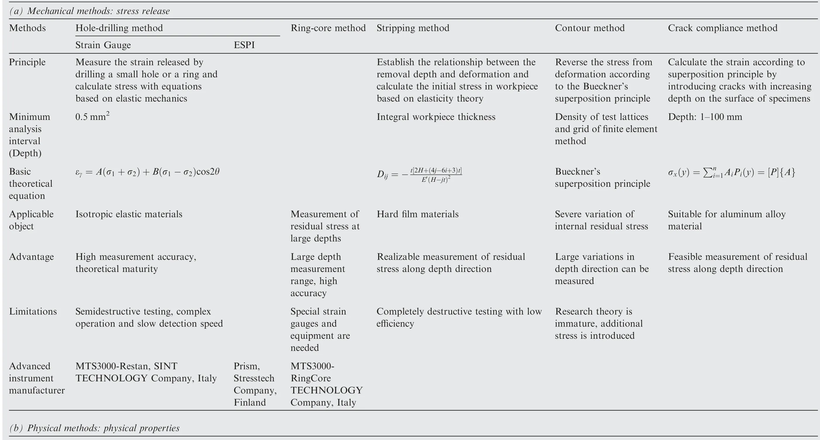
Table 2 Comparison of residual stress measurement methods.
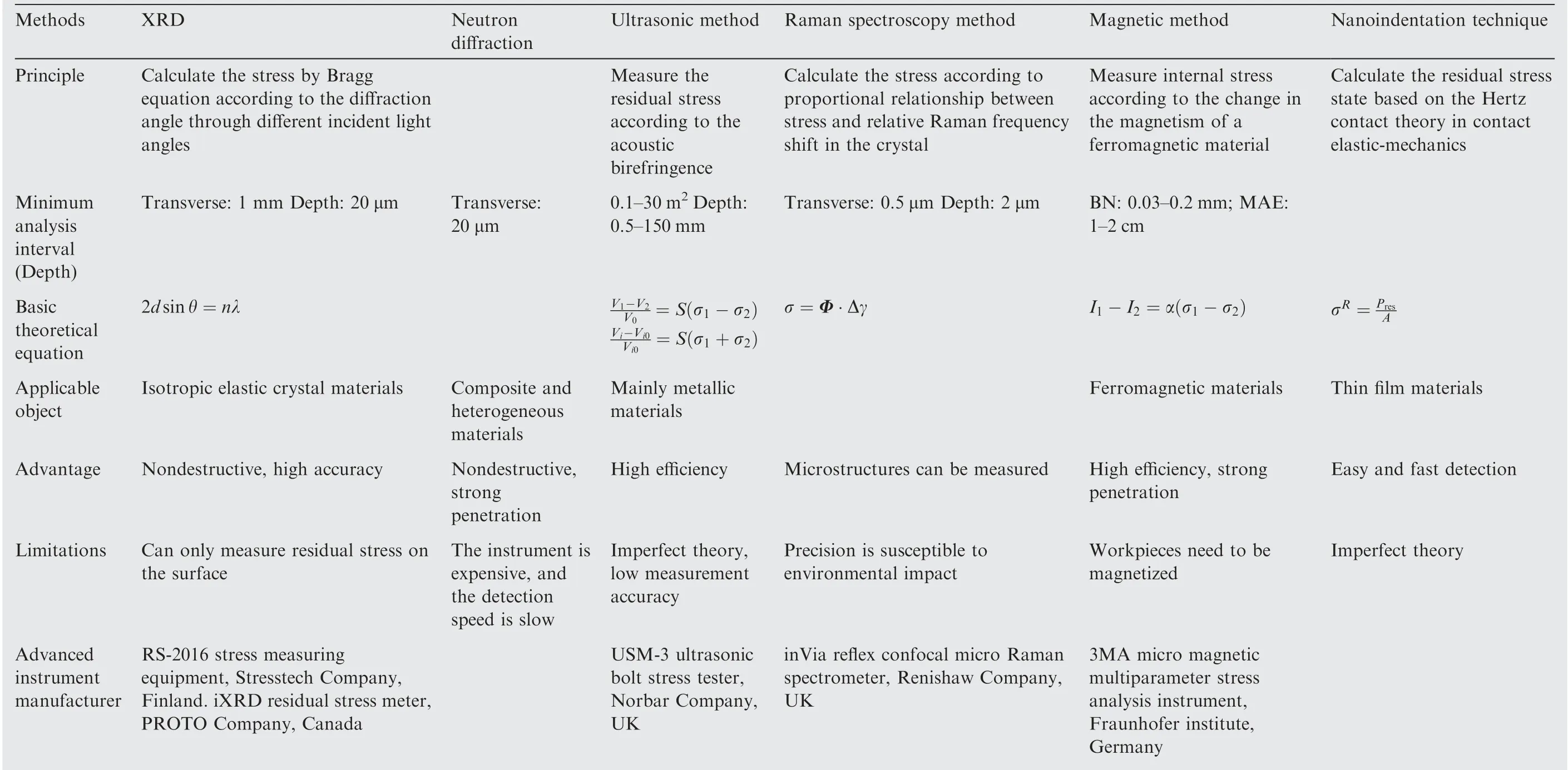
Table 2 (continued)
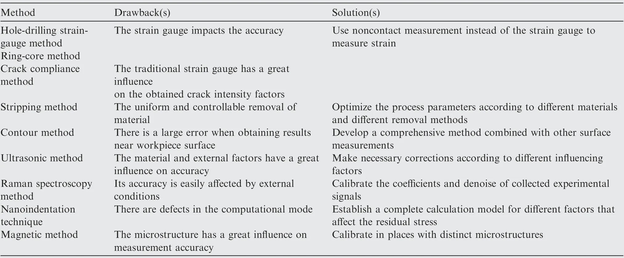
Table 3 Problems with residual stress measurements.
Based on the introduction of the residual stress measuring methods mentioned above, several methods are summarized and compared in Table 2.
4. Summary and future trend of residual stress measurement technology
Residual stress measurement technology has transitioned from destructive to nondestructive methods over several decades.With the discovery of various new physical principles,a variety of measurement methods have been proposed and improved,improving the accuracy and efficiency of residual stress measurements. However, regardless of the measurement method,there are inherent defects in each one.It is necessary to choose the appropriate measurement method according to the actual situation (Table 3).
In addition, in view of the problems existing with the current measurement methods, it may be necessary to study the following in the future.
(1) A combination of two or more measurement methods
In the current research, single measurement methods have their own advantages and disadvantages. Combining two or more measurement methods to complement the advantages of each thereby improves the measurement accuracy,efficiency or realizes measurement in the depth direction. The combination mainly embodies two aspects. One is to make use of the characteristics of different methods to merge various methods into a new method, thus reflecting the characteristics of the new method.The other is to simply use a combination of multiple approaches to solve the problem that can hardly be solved by a single method, such the combination of the stripping method and XRD method.The main difficulty in this direction is to find similarities in the application of related principles between methods.
In the measurement of residual stress,the emergence of new processing methods in mechanical methods and the discovery of new physical phenomena or principles in physical methods provides new approaches for a combination of methods.Chemical methods are seldom used in the measurement of residual stress. At present, chemical reagents have been used to corrode the sample. The relative magnitude and direction of residual stress can be measured qualitatively by observing cracks. It is difficult to observe the generation and development direction of cracks, which limits the development of chemical methods in the quantitative measurement of residual stress.The quantitative characterization of cracks by means of a combination of methods, such as with an optical measurement or acoustic measurement, may be a new approach for the quantitative measurement of residual stress by chemical methods.Observation and characterization of cracks is a challenge. Among the mechanical stress release methods, the most basic strain gauge measurement has been widely applied to various strain measurements. Optical measurement methods have been successfully applied to strain measurements, such as the ESPI hole-drilling method.In the same way,combining the ring-core method with optical measurements can also improve the accuracy of the measurement results.
In terms of the similarities of the principles among the methods, studies have been carried out, such as combining the ultrasonic method with the magnetic method to measure the variation in the shear wave reflection amplitude under different excitation intensities by using an ultrasonic signal.Other magnetic properties,such as coercivity and incremental permeability,can also be used.In this research direction,there is still great room for development, and the key points are how to correlate the advantages of the methods while minimizing an overlap of the disadvantages and ultimately obtain highprecision measurement results.
(2) Accurate measurement of the full field on a twodimensional plane
Among the current measurement methods, many of them have very small measuring areas or can only obtain the average stress on a whole plane. Generally, the residual stress state is unevenly distributed on the two-dimensional plane. The stress reconstruction method is used to obtain the residual stress over the whole field of a two-dimensional plane. The key point is how to determine the stress function,including the basic function of the Airy stress function, in the reconstruction process.In the current research, there are many research methods,111–113but there are still shortcomings, so further research is needed to obtain the criteria for determining a general stress function.
The application of finite element software in residual stress testing and the visualization of the results will have broad prospects for the research and development of residual stress measurement. The application of the finite element method provides a great opportunity for the development of full-field measurement of two-dimensional stress,but there is a problem of too many errors;thus,the research can focus on combining experimental data with finite element simulation.The influencing factors can be used as parameters to optimize the finite element simulation model to obtain results with improved accuracy. The method of obtaining strain data by machine vision provides a new development direction. For example,the full-field plane displacement data after cutting in the contour method can be acquired using machine vision, which enables an improved and realistic plane profile to be obtained,resulting in results with improved accuracy. The visualization of the whole field residual stress measurement results will also become an indispensable research direction. However, due to the limitations of data acquisition accuracy and other factors,progress in this direction is still slow.Therefore,future residual stress measurement methods are expected to develop towards visualizing the results of the whole field residual stress contour plots and applying artificial intelligence.
Acknowledgements
The authors acknowledge the financial support from Science Challenge Project of China (No. TZ2016006-0103 and No.TZ2016006-0107-02), LiaoNing Revitalization Talents Program of China (No. XLYC1807230), Science Fund for Creative Research Groups of NSFC (No. 51621064), the Fundamental Research Funds for the Central Universities of China (No. DUT17RC(3)105) and National Natural Science Foundation of China (No. 51975096).
 CHINESE JOURNAL OF AERONAUTICS2021年2期
- CHINESE JOURNAL OF AERONAUTICS的其它文章
- Recent active thermal management technologies for the development of energy-optimized aerospace vehicles in China
- Electrochemical machining of complex components of aero-engines: Developments, trends, and technological advances
- Micromanufacturing technologies of compact heat exchangers for hypersonic precooled airbreathing propulsion: A review
- Towards intelligent design optimization: Progress and challenge of design optimization theories and technologies for plastic forming
- A combined technique of Kalman filter, artificial neural network and fuzzy logic for gas turbines and signal fault isolation
- Analytical method of nonlinear coupled constitutive relations for rarefied non-equilibrium flows
