Random copolymer membrane coated PBO fibers with significantly improved interfacial adhesion for PBO fibers/cyanate ester composites
Lin TANG, Junliang ZHANG, Junwei GU
Shaanxi Key Laboratory of Macromolecular Science and Technology, School of Chemistry and Chemical Engineering,
Northwestern Polytechnical University, Xi’ an 710072, China Received 28 February 2020; revised 15 March 2020; accepted 25 March 2020
KEYWORDS RAFT polymerization;Membrane;PBO fibers;Bisphenol A cyanate(BADCy) resins;Interfacial adhesion
Abstract Poly(p-phenylene-2,6-benzobisoxazole)(PBO)fibers possess excellent dielectric,mechanical properties and heat resistance.However,the surface of PBO fibers is smooth and highly chemical inert, resulting in poor interfacial compatibility to polymer matrix, which severely limits its wider application in high-performance fiber-reinforced resin matrix composites. In this work, random copolymers(P(S-co-BCB-co-MMA))containing benzocyclobutene in the side-chain were synthesized by reversible addition-fragmentation chain transfer (RAFT) polymerization, which were then utilized to form dense random copolymer membrane on the surface of PBO fibers by thermally cross-linking at 250°C(PBO@P fibers).Four kinds of synthesized P(S-co-BCB-co-MMA)with different number-average molar mass (Mn) were well controlled and possessed narrow dispersity.When the Mn was 32300, the surface roughness of PBO@P fibers was increased from 11 nm(PBO fibers) to 39 nm. In addition, PBO@P fibers presented the optimal interfacial compatibility with bisphenol A cyanate (BADCy) resins. And the single fiber pull-out strength of PBO@P fibers/BADCy micro-composites was 4.5 MPa, increasing by 45.2% in comparison with that of PBO fibers/BADCy micro-composites (3.1 MPa). Meantime, PBO@P fibers still retained excellent tensile strength (about 5.1 GPa). Overall, this work illustrates a simple and efficient surface functionalization method,which would provide a strong theoretical basis and technical support for controlling the surface structure & chemistry of inert substrates.
1. Introduction
High-performance fiber-reinforced polymer composites have been widely used in the fields of aviation/aerospace engineering, defensive technology, automotive engineering,construction, and general industry, due to their high specific modulus/strength, simple molding process, and structural design-ability,and so on.1–4However,the surface of most reinforced fibers is inert to chemicals thus resulting poor interfacial compatibility between fiber and polymer matrix,5–6which severely affects the comprehensive performance of fiberreinforced polymer composites.
Compared with glass fibers(GFs),7Kevlar fibers,8–9carbon fibers (CFs),10and ultrahigh molecular weight polyethylene(UHMWPE) fibers,11poly(p-phenylene-2,6-benzobisoxazole)(PBO) fibers have attracted considerable interests in the field of high-performance fiber-reinforced polymer matrix composites,12–16owing to the excellent mechanical properties (tensile modulus and tensile strength are 280.0 and 5.8 GPa, respectively, much higher than those of GFs and Kevlar fibers), relatively low density (1.56 g/cm3, obviously lower than that of GFs), outstanding heat resistance (the maximum thermal decomposition temperature is 650°C), low moisture absorption, wonderful dielectric constant (ε, 2.6–3.2) and dielectric loss tangent (tanδ, 0.005–0.010). However, the surface of PBO fibers is smooth and highly chemical inert, and displays poor interfacial compatibility with polymer matrix, which severely restricts widespread application of PBO fibers in high-tech fields.17–19
To date, surface functionalization strategies of PBO fibers mainly include chemical,20–21plasma,22and high energy ray treatment,23etc. Chemical treatment refers to grafting active groups onto the surface of PBO fibers through chemical reactions, to improve the interfacial compatibility with polymer matrix. However, chemical treatment usually requires acid treatment, which will destroy the crystalline structure of PBO fibers, therefore, reduce the mechanical properties of PBO fibers. For example, Hu et al.17grafted metal–organic framework (MOF, UIO-66) onto the surface of PBO fibers(PBO@UIO-66 fibers), and the interfacial bonding strength with epoxy resins was increased by 49.0%. However, the intrinsic tensile strength of PBO@UIO-66 fibers decreased from 4.91 GPa (PBO fibers) to 3.44 GPa. Plasma and high energy ray treatments rely on high energy to break the benzene and oxazole rings of PBO fibers to generate active groups such as hydroxyl(–OH)and carboxyl(–COOH),thereby increasing the interfacial bonding strength with polymer matrix. Song et al.24adopted oxygen plasma to functionalize PBO fibers(O-PBO fibers), and the interfacial bonding strength with epoxy resins increased by 39.8%.However,the intrinsic tensile strength of O-PBO fibers decreased from 5.1 GPa(PBO fibers)to 4.6 GPa. Similarly, Liu et al.25adopted air plasma (Air,50 W/cm-2) to functionalize the surface of PBO fibers, and the intrinsic tensile strength was also reduced from 5.6 GPa(PBO fibers) to 5.0 GPa. It can be seen that the above mentioned high-strength and high-energy surface functionalization methods could effectively improve the surface activity of PBO fibers, but the main structure of PBO fibers is always destroyed. Therefore, such methods cannot give full play to the excellent comprehensive performance of PBO fibers.Apart from the aforementioned approaches,introducing a new interfacial phase between PBO fibers and polymer matrix can also improve the interfacial bonding strength. In our previous work,26synthetic epoxy-terminal PBO precursor (epoxyprePBO) was introduced into bisphenol A cyanate resins(BADCy) to obtain PBO-co-BADCy modified resins containing PBO structure. When the amount of epoxy-prePBO is 7 wt%, PBO-co-BADCy resins possess the optimal comprehensive properties. However, the introduction of new interfacial phase also increases the interfacial polarization, thereby increasing the dielectric loss of the PBO fibers/PBO-co-BADCy modified resins composites.
In recent years, more and more researchers are paying attention to surface functionalization of materials utilizing polymer membrane with specific structures.27–30Dopamine(DA) can form polymer networks (polydopamine, PDA)through oxidative cross-linking to firmly adhere onto polytetrafluoroethylene (PTFE),31silver,32boron nitride (BN),33Kevlar fibers,9PBO fibers,34and other inert substrate surfaces.35However, DA usually needs to undergo oxidative self-polymerization in an alkaline buffer solution, and the molar mass of PDA is uncontrollable, resulting in uneven membrane thickness and incomplete coverage of the substrate,which would affect the adhesion properties of PDA to substrate surfaces.Chen et al.36adopted DA to modify the surface of PBO fibers(PBO@PDA fibers),and the interfacial bonding strength with epoxy resins increased by 16.6%.In our previous research,37DA and KH-560 were synchronously used to functionalize the surface of PBO fibers (f-PBO fibers), and the interfacial bonding strength with modified BADCy resins was increased by 25%. Controlled radical polymerization(CRP), such as nitroxide-mediated polymerization (NMP),38atom transfer radical polymerization(ATRP),39and reversible addition-fragmentation chain transfer (RAFT) polymerization, have been widely applied to synthesize polymers with controlled architectures and molar mass, and narrow dispersity.40–44Therefore, polymers with designed structures and functionalities can be synthesized on demand via CRP technique.45–46Venkidasubramonian et al.47adopted surfaceinitiated-RAFT polymerization to synthesize poly(methyl methacrylate) (PMMA) and poly[2-(methacryloyloxy) ethyl]dimethyl-(3-sulfopropyl)ammoniumhydroxide (PMEDSAH)brushes, which could increase the reactivity of parylene. Hou et al.48grafted poly(2-(dimethylamino)ethyl methacrylate)-block-polystyrene (PDMAEMA-b-PS) onto the surface of silica through RAFT polymerization, and the components and morphologies of PDMAEMA-b-PS could be precisely controlled. In addition, Ryu et al.49designed and synthesized a random copolymer(P(S-co-BCB-co-MMA))via nitroxide radical polymerization (NMRP), then the P(S-co-BCB-co-MMA)was used to form a random copolymer network membrane by thermal cross-linking,which possessed excellent adhesion with inert substrates. And even without chemical bonding to the surface of inert substrates, adhesive failure of the membrane was not observed.These researches provide a simple and effective method for surface structure optimization and functionalization of inert matrix. The disadvantage is that NMRP presents a narrow range of applicable monomers(uncontrolled polymerization of methacrylate monomers) and a high polymerization temperature (120°C).50,51
In this work, styrene (S), 4-vinylbenzocyclobutene (BCB),and methyl methacrylate (MMA) were performed as monomers to synthesize random copolymers P(S-co-BCB-co-MMA) containing benzocyclobutene in the side-chain by RAFT polymerization, followed by forming random copolymer membranes through thermally cross-linking to coat the surface of PBO fibers (PBO@P fibers), which was expected to achieve better interfacial bonding strength between PBO fibers and BADCy resins without damaging the intrinsic structure of PBO fibers. Structure and performance of the P(S-co-BCB-co-MMA) were analyzed and characterized using1H nuclear magnetic resonance (1H NMR), Fourier transform infrared (FTIR) spectroscopy, gel permeation chromatography(GPC),thermal gravimetric analyzer(TGA),and differential scanning calorimetry (DSC). Besides, the P(S-co-BCB-co-MMA) molar mass affecting on the surface roughness, intrinsic tensile strength, and interfacial bonding strength with BADCy resins of PBO@P fibers were investigated.
2. Experimental part
2.1. Main raw materials
Poly(p-phenylene-2,6-benzobisoxazole) (PBO) fibers, with the density of 1.56 g/cm3, were purchased from Toyobo Co. Ltd.(Osaka, Japan). Bisphenol A cyanate ester (BADCy) resins,with the molecular weight of 278 g/mol, were purchased from Jiangdu Wuqiao Resin Factory Co. Ltd. (Jiangsu, China). 4-vinylbenzocyclobutene (BCB) was supplied by Saen Chemical Technology Co., Ltd. (Shanghai, China). Styrene (S, 99.5%,stable with 4-tert-butylcatechol)and 1,1′-azobis(cyclohexane-1-carbonitrile)were both purchased from Shanghai Aladdin Biochemical Co., Ltd. (Shanghai, China). Methyl methacrylate(MMA,99.8%)and 1,3,5-trioxane(99.5%)were both received from Shanghai Macklin Biochemical Co., Ltd. (Shanghai,China). 4-cyano-4-[(dodecylsulfanylthiocarbonyl)sulfanyl]pen tanoic acid (CTA, 97%) was obtained from Sinocompound Metal catalysts & Ligands Co., Ltd. (Nanjing, China). nhexane (97%) and dichloromethane (99.9%) were both purchased from Nanjing Aikang Chemical Co., Ltd. (Nanjing,China). Deuterated chloroform (99.8%) was received from Jiuding chemical technology Co.,Ltd.(Shanghai,China).
2.2. Synthesis of P(S-co-BCB-co-MMA)
Styrene (S, 26.1 mmol), methyl methacrylate (MMA,11.3 mmol), 4-vinylbenzocyclobutene (BCB, 1.4 mmol), 4-cya no-4-[(dodecylsulfanylthiocarbonyl)sulfanyl]pentanoic acid(CTA,0.2–0.02 mmol),1,1′-azobis(cyclohexane-1-carbonitrile)(initiator/CTA=1:5, n/n) and 1, 3, 5-trioxane (as an internal standard, 40 mg) were added into a round bottom flask and sealed with a rubber septum.The above mixture was degassed for 15 minutes using nitrogen and then stirred for 24 h in an 80°C oil bath under nitrogen protection. Finally, the reaction mixture was precipitated 3–4 times in n-hexane to obtain the P(S-co-BCB-co-MMA) with different Mn, denoted as P(S-co-BCB-co-MMA)-1, P(S-co-BCB-co-MMA)-2, P(S-co-BCBco-MMA)-3,and P(S-co-BCB-co-MMA)-4,respectively.Schematic diagram for preparation of P(S-co-BCB-co-MMA) is shown in Scheme 1(a). The theoretical number-average molar mass (Mn,th) is calculated using Eq. (1).

where, M and n represent the molar mass and amount of substance of S, BCB, MMA, and RAFT, respectively, and X represents the respective conversion of S,BCB,and MMA,which can be calculated by1H NMR before and after the reaction.
2.3. Preparation of P(S-co-BCB-co-MMA) coated PBO fibers
PBO fibers were soaked in absolute ethanol for 24 h,and dried in a vacuum oven at 80°C,which were then treated by P(S-co-BCB-co-MMA) solutions (0.3 wt%) to obtain PBO/P fibers after natural volatilization of the solvent(methylene chloride).Next, the PBO/P fibers were placed into a tube furnace, and treated at 250°C for 10 min under nitrogen protection.Finally, the PBO@P fibers were obtained after cooling to room temperature, denoted as PBO@P-1, PBO@P-2,PBO@P-3, and PBO@P-4, respectively. Schematic diagram of surface coating functionalization for PBO fibers is shown in Fig. 1.
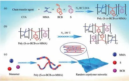
Scheme 1 Schematic diagram of preparation for P(S-co-BCB-co-MMA) (a) and random copolymer membranes ((b) and (c)).
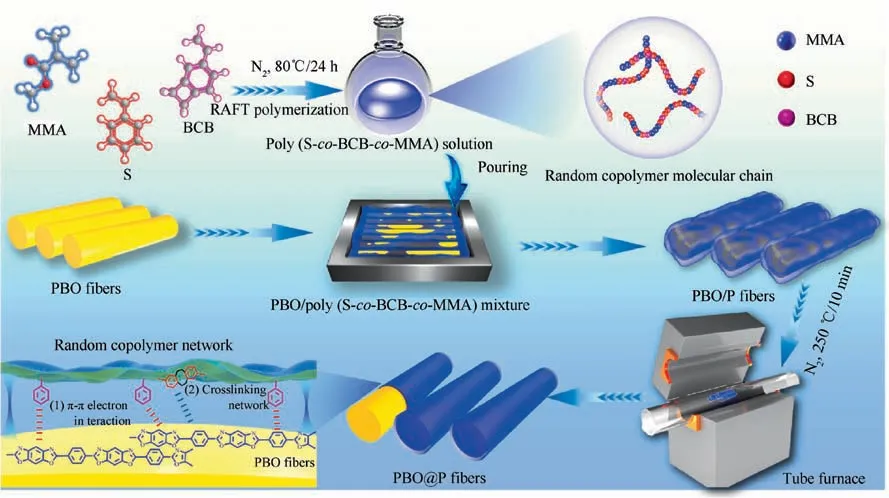
Fig. 1 Schematic diagram of surface functionalization for PBO fibers.
2.4. Characterizations
1H nuclear magnetic resonance(1H NMR)spectra of the samples were performed on a Bruker Avance 400 MHz (Bruker Bio Spin, Switzerland) to determine the molecular structure,with CDCl3as solvent and tetramethylsilane (TMS) as an internal standard. Fourier transform infrared (FTIR) spectra of the samples were obtained on Bruker Tensor 27 equipment(Bruker Corp., Germany). X-ray photoelectron spectroscopy(XPS)analyses of the samples were carried out by Kratos Axis Ultra DLD equipment (Kratos Corp., UK). X-ray diffraction(XRD) of the samples was carried out on a Shimadzu-7000 type X-ray diffraction (λ=0.154 nm, Shimadzu, Japan).Thermogravimetric analyses (TGA) of the samples were carried out by STA 449F3 (NETZSCH C Corp., Germany) at 10°C/min (argon atmosphere), over the whole range of temperature (40–800°C). Differential scanning calorimetry(DSC)analyses of the samples are carried out at 10°C/min(nitrogen atmosphere) (Mettler-Toledo Corp., Switzerland). Gel permeation chromatography (GPC) of the samples were performed at 25°C using a waters1515 (Waters Corp., America)equipment. Scanning electron microscope (SEM) morphologies of the samples were observed using a VEGA3-LMH(TESCAN Corp., Czech Republic). Transmission Electron Microscope (TEM) images of the samples were collected on a Talos F200X/TEM microscope (FEI Company). Atomic Force Microscope(AFM)images of the samples were collected by a Dimension Fast Scan AFM (Bruker Corp., Germany) to characterize the surface roughness of PBO fibers. Tensile strength of the samples was measured by single fiber electronic tensile strength tester of YM-06B (Laizhou Yuanmao Instrument Corp., China) according to the standard of ASTM D3379-75, and at least 30 specimens of each sample for PBO fibers were tested. Single fiber pull-out strength of the samples was performed to estimate the interfacial compatibility of PBO fibers and BADCy resins by single fiber electronic tensile strength tester of YM-06B (Laizhou Yuanmao Instrument Corp., China). Prior to single fiber pull-out strength experiment, BADCy was dropped into PBO fiber through a syringe to form BADCy microbeads, followed by programmed heating-up curing procedure at 160°C/1h+180°C/2h+200°C/5h+220°C/2h to obtain PBO fibers/BADCy micro-composites. At least 30 specimens were recorded and averaged per sample. The available values of single fiber pull-out strength can be calculated by the Eq. (2).

where, F corresponds to the maximum applied load, D is the diameter of a single filament, and L is the imbedding length of the BADCy in PBO fibers/BADCy micro-composites.
3. Results and discussion
3.1. Structure and performance of the P(S-co-BCB-co-MMA)
1H NMR spectra of the polymerization at t=24 h are shown in Fig. 2. The conversion of S and BCB was determined by comparing vinyl peak (δ=5.07–5.29 ppm) before and after reaction. Similarly, the conversion of MMA was determined by comparing propenyl peak (δ=6.40–6.48 ppm) before and after reaction.Fig.3 shows the1H NMR(Fig.3(a))and FTIR(Fig. 3(b)) spectra of the P(S-co-BCB-co-MMA). Table 1 presents the corresponding monomer conversion, Mn,th, Mnby GPC, and polymer dispersity index (PDI). In Fig. 3(a), the protons(5.5 ppm and 6.5 ppm,Fig.1)for vinyl(S)and propenyl (MMA) disappears. Moreover, P(S-co-BCB-co-MMA)shows the signals of protons in the main chain at 1.50–2.50 ppm, and the methyl and benzocyclobutene at 3.50–3.60 and 3.02–3.16 ppm,respectively.In addition,the band around 2930/2850 cm-1and 1760 cm-1in the FTIR spectrum for P(Sco-BCB-co-MMA) can be assigned to the methylene (–CH2-)and ester bond (–COO-), respectively. Besides, the vibration peak for benzene ring of the P(S-co-BCB-co-MMA) at 1450–1600 cm-1is also observed. Fig. 3(c). shows the GPC curves of P(S-co-BCB-co-MMA) with four Mn(5700, 10700,32300, and 53300), which can be obtained by adjusting the ratio of monomers and RAFT reagent (In the ordinate of Fig. 3(c), W represents the weight of the P(S-co-BCB-co-MMA), and W(lgMn) represents the amount of substance of the P(S-co-BCB-co-MMA) with a certain Mn). It can be seen that the measured Mnof the P(S-co-BCB-co-MMA) by GPC is closed to the theoretical Mn,and the PDI presents low value,indicating that the polymerization was well controlled. Meanwhile, according to monomer conversion (Table 1), the molar ratio of S/BCB/MMA for P(S-co-BCB-co-MMA)is calculated to be close to 56/2/4. It can be deduced that the P(S-co-BCB-co-MMA) with different Mnhave been successfully synthesized.
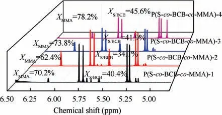
Fig.2 1H NMR spectra for RAFT polymerization for synthesis of P(S-co-BCB-co-MMA) showing the monomer conversion for each block (S, BCB, and MMA).
Fig.4 shows the DSC and TGA curves of the P(S-co-BCBco-MMA), and Table 2 presents the characteristic thermal data. As illustrated in Fig. 4(a) and Table 2, four kinds of P(S-co-BCB-co-MMA) display obvious exothermic reaction at about 250°C (cross-linking temperature, TCross-linking), which is ascribed to ring-opening cross-linking reaction of the cyclobutene (BCB) on the P(S-co-BCB-co-MMA) side chain(Scheme 1(b) and (c)). From Table 2, the glass transition temperature (Tg) and 30% thermal weight loss temperature(T30)52,53of the P(S-co-BCB-co-MMA) both increase with the increasing of Mn,mainly attributed to the fact that the proportion of chain-end segments (greater mobility) decreases with the increasing of Mn, thereby reducing the overall free volume and resulting the decreased Tgvalues54. In addition,the van der Waals force between polymer chains also increases as the Mnincreases, resulting in relatively better heat resistance. And the T30values of the four kinds of P(S-co-BCB-co-MMA) are all around 390°C, much higher than the temperature of cross-linking reaction(250°C),further indicating that the P(S-co-BCB-co-MMA) could not be damaged under 250°C treatment.
3.2. Structure and performance of PBO and PBO@P fibers
FTIR spectra of PBO and PBO@P fibers(taking PBO@P-3 as an example)are presented in Fig.5(a),the bands around 1620,1500, and 3058 cm-1of PBO fibers correspond to the stretching vibration peaks of C=C,C–C of the benzene ring,and C–H,respectively.Besides,the vibration peaks of the oxazole ring appear at 1628 cm-1(C=N) and 1050 cm-1(C-O-C). For PBO@P-3 fibers, new characteristic peak near 1760 cm-1(–COO-) is observed, mainly attributed to –COO- on the side chain of the P(S-co-BCB-co-MMA)-3. Fig. 5(b1) shows the XPS curves of PBO and PBO@P fibers. PBO fibers possess three characteristic peaks of C1s,N1s,and O1s.The N1s peak of PBO fibers (Fig. 5(b2)) has only one C=N–C (398.9 eV)peak, corresponding to the oxazole ring, and the C1s peak(Fig. 5(b3)) at 284.8, 285.8, 286.8, and 288.1 eV correspond to C–C, C–N, C–O, and N–C=O, respectively. After the cross-linking coating of P(S-co-BCB-co-MMA), only two peaks of C1s and O1s are presented in PBO@P fibers (Fig. 5(b1)),and the relative content of C and O elements of PBO@P fibers increases (Table 3). In addition, the N–C=O peak(288.1 eV,Fig.5(b3))correlated to the oxazole ring of PBO@P fibers disappears, and a new signal at 289.2 eV (O–C=O,Fig. 5(b4)) for the C1s peak appears. It is mainly attributed to the coated random copolymer membrane of P(S-co-BCBco-MMA) on the surface of PBO fibers. In Fig. 5(c), three obvious peaks, corresponding to 16.1° (200), 25.6° (010), and 27.3°(210),are observed in XRD curves of PBO and PBO@P fibers, and the shape and size of their peaks are basically the same, indicating that the crystal structure of PBO@P fibers is not destroyed. Fig. 5(d) shows the TGA curves of PBO and PBO@P fibers. The weight loss of PBO fibers before 600°C is less than 1 wt%, probably due to the loss of water and residual sizing agent on the surface of PBO fibers. And the weight loss of PBO fibers at 800°C reaches 31.3 wt%,ascribed to the degradation of PBO molecular chains at high temperatures. After the cross-linking coating of P(S-co-BCBco-MMA), the weight loss of PBO@P fibers presents two stages, the first stage of weight loss is occurred around 350°C, mainly due to the degradation of the P(S-co-BCB-co-MMA) (consistent with the results of Fig. 5(b)). The second stage of weight loss is occurred around 600°C,attributed to the molecular chains of PBO fibers starting to break down. In addition, the weight loss at 800°C of four PBO@P fibers reached 34.8 wt% (PBO@P-1), 35.0 wt%(PBO@P-2), 35.3 wt% (PBO@P-3), and 35.6 wt% (PBO@P-4), respectively, indicating that the content of the P(S-co-BCB-co-MMA) coated on the surface of PBO fibers is about 4 wt%. From Fig. 5(e)-(f), the intrinsic tensile strength of four PBO@P fibers is around 5.1 GPa, further confirming that PBO@P fibers still possess excellent mechanical properties after cross-linking coating of P(S-co-BCB-co-MMA).

Fig. 3 1H NMR, FTIR, and GPC of P(S-co-BCB-co-MMA).

Table 1 Monomer conversion (%), theoretical number-average molar mass (Mn,th), Mn, and PDI of the P(S-co-BCB-co-MMA).
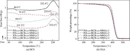
Fig. 4 DSC and TGA curves of P(S-co-BCB-co-MMA).

Table 2 Characteristic thermal data of P(S-co-BCB-co-MMA).
3.3. Interfacial compatibility of PBO fibers/BADCy and PBO@P fibers/BADCy micro-composites
Fig. 6(a)–(e) and (a1)–(e1) show the SEM and AFM morphologies of PBO and PBO@P fibers. Surface of PBO fibers is smooth (Fig. 6(a)), and the surface roughness (Fig. 6(a1))is about 11 nm, mainly due to highly oriented PBO molecular chains. After the cross-linking coating of P(S-co-BCB-co-MMA), the surface of PBO@P fibers (Fig. 6(b)–(e)) shows obvious wrinkles, and the surface roughness is gradually increased with the increasing of Mn. The maximum surface roughness is about 42 nm for PBO@P-4 fibers (Fig. 6(e1)),much higher than that of PBO fibers (11 nm). The reason is that randomly oriented copolymer P(S-co-BCB-co-MMA)forms a new surface layer on the surface of PBO fibers. In addition, the degree of intertwining between the P(S-co-BCBco-MMA) molecular chains also increases with the increasing of the Mn,increasing surface roughness of the random copolymer membrane. Fig. 6(f) displays the single fiber pull-out strength of PBO fibers/BADCy and PBO@P fibers/BADCy micro-composites and Fig. 6(a2)–(e2) show the corresponding SEM images of PBO and PBO@P fibers surfaces after single fiber pull-out test.The single fiber pull-out strength of PBO@P fibers/BADCy micro-composites increases firstly, but then decreases as the Mnincreases. When the Mnof P(S-co-BCBco-MMA)is 32300,the maximum single fiber pull-out strength is 4.5 MPa for PBO@P-3 fibers/BADCy micro-composites,increased by 45.2%, compared with that of PBO fibers/BADCy micro-composites (3.1 MPa). The reason is that the surface of PBO fibers is smooth, resulting in poor interfacial compatibility with BADCy resins (Fig. 6(a2), no BADCy resins on the surface of PBO fibers after single fiber pull-out test). Besides, P(S-co-BCB-co-MMA) and PBO fibers can interact with each other through π-π electrons on the benzene ring.Within a certain molar mass range,the π-π electron interaction is stronger as the Mnof the P(S-co-BCB-co-MMA)increases. Meanwhile, the P(S-co-BCB-co-MMA) forms dense and uniform random copolymer membrane on the surface of PBO fibers through ring-opening cross-linking, which makes it possess stronger adhesion to PBO fibers, thereby further increasing the interfacial bonding strength between PBO@P fibers and BADCy resins (Fig. 6(b2)–(d2), as the Mnof the P(S-co-BCB-co-MMA) increases, the residual BADCy resins on the surface of PBO@P fibers also gradually increases).However, when the Mnof the P(S-co-BCB-co-MMA) is too large (53300), the formed membrane by P(S-co-BCB-co-MMA)-4 presents higher hardness and brittleness, resulting in poor membrane-forming performance. And the cohesion between P(S-co-BCB-co-MMA)-4 molecular chains exceeds its adhesion, which results in poor adhesion to PBO fibers,thereby further decreasing the interfacial bonding strength between PBO@P-4 fibers and BADCy resins. In Fig. 6(e2),the interface failure mode of PBO@P-4 fibers/BADCy micro-composites is that the membrane (P(S-co-BCB-co-MMA)-4) is detached from PBO@P-4 fibers. TEM images of cross-sections for PBO fiber/BADCy and PBO@P-3 fibers/BADCy micro-composites are shown in Fig. 6(g)–(h). It can be observed that the cross section of the PBO fibers/BADCy micro-composites displays obvious fibers and resin phases(narrow boundary for interfacial phase). After cross-linking coating of P(S-co-BCB-co-MMA)-3, a clear interfacial phase(thickness about 60 nm) appears in the cross section for PBO@-3 fibers/BADCy micro-composites. Fig. 6(i) shows the interfacial bonding strength for polymer matrix with PBO@P-3 fibers and other functionalized PBO fibers reported in previous literatures. Although the conventional surface functionalization methods can increase the interfacial bonding strength between the PBO fibers and polymer matrix, the intrinsic tensile strength of PBO fibers is decreased at the same time. While some of the approaches can retain the excellent tensile strength of the PBO fibers, the effect of improving the interfacial bonding strength between functionalized PBO fibers and polymer matrix is not satisfactory.PBO@P-3 fibers in our work,prepared by cross-linking coating of the P(S-co-BCB-co-MMA) (Mn, 32300), present excellent interfacial bonding strength with BADCy resins, while still maintain excellent mechanical properties.
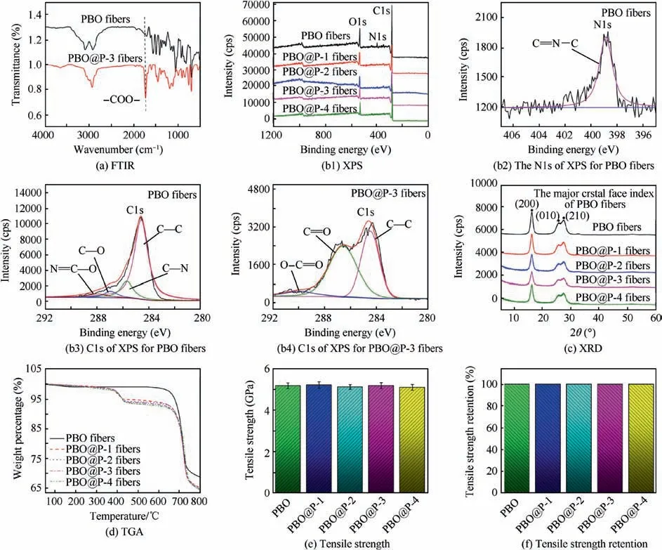
Fig.5 FTIR of PBO and PBO@P-3 fibers; XPS of PBO and PBO@P fibers,high-resolution XPS of N1s for PBO fibers,C1s for PBO and PBO@P-3 fibers; XRD, TGA, tensile strength and retention of PBO and PBO@P fibers.
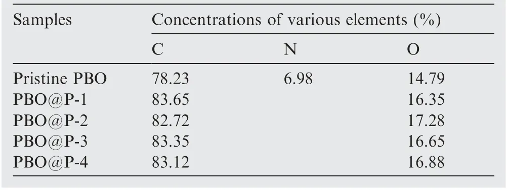
Table 3 Concentrations of various elements on the surface of PBO fibers.
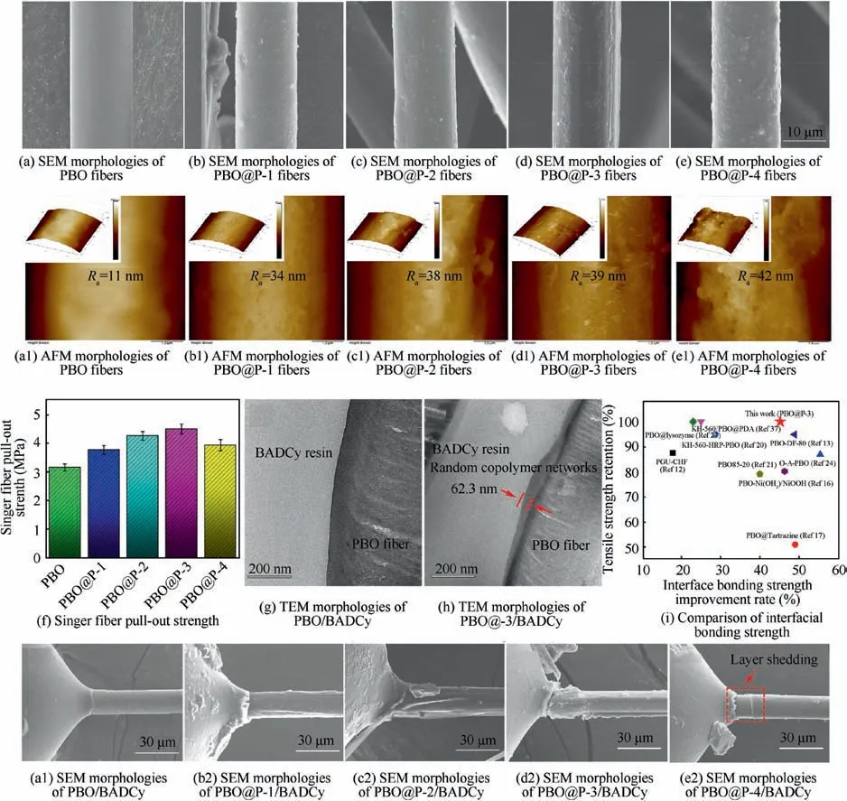
Fig.6 SEM,and AFM morphologies of PBO and PBO@P fibers;Single fiber pull-out strength of the PBO fibers/BADCy and PBO@P fibers/BADCy micro-composites;TEM morphologies of PBO fiber/BADCy and PBO@P-3 fiber/BADCy micro-composites;Comparison of interfacial bonding strength for polymer matrix with PBO@P-3 fibers and other functionalized PBO fibers reported in previous literatures; SEM images of PBO and PBO@P fibers surfaces after single fiber pull-out test.
4. Conclusions
(1).1H NMR, FTIR, and GPC analyses indicated that four kinds of P(S-co-BCB-co-MMA)with low PDI were successfully synthesized. DSC, TGA, SEM, AFM, and TEM analyses demonstrated that the P(S-co-BCB-co-MMA) and PBO fibers interacted with each other through π-π electrons of the benzene ring. And the formed P(S-co-BCB-co-MMA) membrane by thermally cross-linking uniformly covered the surface of PBO fibers.
(2). When the Mnof P(S-co-BCB-co-MMA) was 32300, the surface roughness of PBO@P-3 fibers was increased from 11 nm (PBO fibers) to 39 nm. In addition,PBO@P-3 fibers presented the optimal interfacial compatibility with BADCy resins.
(3). Single fiber pull-out strength of the PBO@P-3 fibers/BADCy micro-composites was 4.5 MPa, increasing by 45.2% in comparison with that (3.1 MPa) of PBO fibers/BADCy micro-composites. Meantime, the PBO@P-3 fibers still retained excellent intrinsic tensile strength (about 5.1 GPa).
(4). Overall, this work illustrates a simple and efficient surface functionalization method, which would provide a strong theoretical basis and technical support for controlling the surface structure & chemistry of inert substrates.
Acknowledgements
The authors are grateful for the support and funding from National Scientific Research Project; Space Supporting Fund from China Aerospace Science and Industry Corporation(2019-HT-XG); Fundamental Research Funds for the Central Universities (310201911qd003); China Postdoctoral Science Foundation(2019M653735);We would like to thank the Analytical & Testing Center of Northwestern Polytechnical University for SEM, AFM, and TEM tests.
 CHINESE JOURNAL OF AERONAUTICS2021年2期
- CHINESE JOURNAL OF AERONAUTICS的其它文章
- Recent active thermal management technologies for the development of energy-optimized aerospace vehicles in China
- Electrochemical machining of complex components of aero-engines: Developments, trends, and technological advances
- Recent progress of residual stress measurement methods: A review
- Micromanufacturing technologies of compact heat exchangers for hypersonic precooled airbreathing propulsion: A review
- Towards intelligent design optimization: Progress and challenge of design optimization theories and technologies for plastic forming
- A combined technique of Kalman filter, artificial neural network and fuzzy logic for gas turbines and signal fault isolation
