Trajectory optimization of aerial slung load release for piloted helicopters
Luofeng WANG, Renliang CHEN, Xufei YAN
National Key Laboratory of Science and Technology on Rotorcraft Aeromechanics, Nanjing University of Aeronautics and Astronautics, Nanjing 210016, China
KEYWORDS Helicopter slung load systems;Nonlinear equations;Optimal control;Pilot inputs;Slung load release;Trajectory optimization
Abstract This study aims to provide the pilot with optimal control time histories for stabilization of a helicopter after releasing the slung load in aerial delivery missions.A model with 21 degrees of freedom (21-DOF) has been developed and validated for a helicopter slung load system. The control history is generated with detailed procedure based on trajectory optimization. Effects of the objective function formulation on the results are discussed and rules are obtained to assist in the objective function determination.We conclude that the pilot should first decrease and then increase the collective control and adjust the longitudinal control to stabilize the helicopter after the in-hover slung load release. The obtained control history is reasonable and helpful for safety and efficiency improvement. Effects of path constraints and the Flight Control System (FCS) are studied. More stringent path constraints will lead to longer time spent and more controls. Stronger stiffness and weaker damping from the FCS will cause milder control histories but sharper on-axis state histories.
1. Introduction
Helicopter transportation with an underneath external slung load is widely used because of fewer restrictions on load shape and fewer requirements for airports compared with in-cabin or airplane transportation. However, despite the widespread usage, the safety of helicopter slung load missions remains a severe problem.According to the investigation by the National Transportation Safety Board, over 10% of accidents are related to helicopter external load operations. In these accidents, pilot errors are one of the most common probable causes.1It would be helpful in reducing pilot errors if the pilot could be informed of the optimal control time history for specific dangerous external slung load operations, thus improving safety and efficiency of these operations.
This paper takes the accurate aerial delivery mission as an example. After reaching the drop zone, the helicopter is required to release the slung load. Before the release, the helicopter slung load system is in an equilibrium state. After the release, the tension in the sling disappears immediately such that the helicopter cannot keep the equilibrium state. Therefore, it will be dangerous if the pilot cannot control appropriately to stabilize the helicopter.
However,few studies have been conducted on the stabilization of helicopters after the release. Ning2developed an efficient contact-friction model for high-fidelity cargo airdrop simulation, but the simulation results are only suitable for cargo airdrop from cabin. Most relevant studies focused on modeling,analysis and stability augmentation of the helicopter slung load system.3–7Recently, Lee studied the control law of the small scaled helicopter for stabilization and trajectory tracking after airdrop.8Chen and Shi9designed the controller for the airdrop mission of an airplane. Sadeghzadeh et al.10designed the payload drop controller for a quad rotor aircraft.In all the above circumstances, the aircraft can be stabilized rapidly with the advanced automatic control systems. However, it is not suitable to apply such control systems to a piloted helicopter, because the pilot will find it violating the intuition if no extra manipulations are required after releasing a heavy slung load.Furthermore,the control system authority of such a piloted helicopter is usually limited, increasing the possibility of controller saturation. Therefore, the practical control after the release is a combination of large amplitude pilot manipulations and small amplitude controller corrections.
This study aims to generate the optimal control time history to stabilize the helicopter after slung load release for the reference of pilots to reduce pilot errors and thus improve safety and efficiency. To achieve this goal, in Section 2, we develop and validate the system model of a full scaled single main rotor helicopter with an underneath slung load,using the data of the UH-60A helicopter and the CONEX container. The system model is a tradeoff between accuracy and computational efficiency. Then, in Section 3, according to the optimal control theory, the generation of the optimal control and state time histories is formulated into a Nonlinear Optimal Control Problem (NOCP), which is then be solved by a numerical method of high robustness and effectiveness.Finally,Section 4 analyzes the different optimization results from different weight coefficient assignments to reveal the inherent laws to determine the final configuration of the objective function.Meanwhile, the effects of path constraints and the FCS on the optimization results are discussed at the end of this section.
2. Development and validation of flight dynamic model
2.1. Model development
The high-order flight dynamic model is not suitable for this study because of the numerical computational cost of subsequent optimization procedures. Since a helicopter cannot fly at high speed with a slung load,the shock wave at the advancing blade and the dynamic stall at the retreating blade are neglected. The rotor force and moment calculation method for analytically integrating the blade force over the rotor disk are of enough precision in this study.
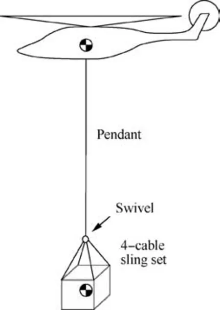
Fig. 1 Helicopter slung load system configuration.
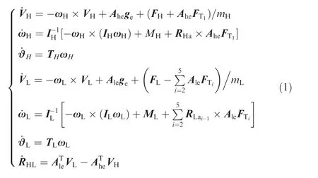
As is shown in Fig.1,the helicopter and the slung load are both 6-DOF rigid body models. The suspension system consists of a long pendant and a 4-cable sling set connected with each other through a swivel such that the yaw moment is not passed to the helicopter, which is described in detail by Gassaway et al.11A single sling in the suspension system is modeled as a stretch-only spring-damp system with 3-DOF,1 stretching motion and 2 swing motions. Because of the large stiffness of the slings, the frequencies of the internal DOFs of the suspension system are much higher than those of other DOFs of the whole model. Consequently, it is assumed that the internal DOFs of the slings will reach equilibrium in an instant.Therefore,the DOFs of the suspension system could be reduced to 3 DOFs, the relative position from the helicopter to the slung load. Several kinematic relations are imposed in the system,bringing 9 extra DOFs such that a 21-DOF helicopter slung load model can be established.
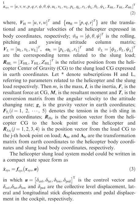
The mathematical model of the helicopter is a simplification of the model developed by Howlett12with the application of the simplified main rotor system model based on the model introduced by Chen,13in which tip-path plane flapping motion is included. Forces and moments of the main rotor are calculated through the analytically integrated equations13modified by the well-known Pitt-Peters dynamic inflow model.14The tail rotor model is simplified from the main rotor model, in which only the lift and collective pitch are considered. The aerodynamic forces and moments of the fuselage, the horizontal empennage, the vertical fin and the slung load are calculated by the interpolation method based on wind tunnel test date tables. All the slings in the suspension system are modeled as linear elastic with a certain stiffness and damping. The total system model and the system state vector can be respectively written as
2.2. Model validation
The helicopter model and the slung load model use the data of the UH-60A helicopter and the CONEX container respectively. The weight of UH-60A is set as 7257.6 kg, the altitude 500 m, the temperature 15 degrees Celsius, and the wind condition is calm. Basic parameters of the suspension system are listed in Table 1, which are presented in Refs. 11,15 in detail.
Due to the lack of test results of trimmed characteristics of the UH-60 helicopter and CONEX container, only pilot controls and the trail angle can be validated. As is presented in Fig. 2, simulation results show good agreement with the flight test values.11Because of the complicated nonlinear aerodynamic environment around the tail rotor and the assumption of zero side slip angle in simulation, a deviation exists in thepedal displacement graph. In Fig. 3, the calculated trail angle of the suspension system is also close to that of the flight test.11Nonlinear unsteady aerodynamic forces of the CONEX container cause the larger difference at high speed. Since the purpose is to stabilize the helicopter after the release in hover,the slung load is separated from the helicopter. Hence, the accuracy of the response calculation of the helicopter in hover is more important. In Fig. 4, the on-axis transient step response characteristics of UH-60 in hover calculated by this model are compared to those calculated by Gen Hel model16which is of good credibility and has been implemented in the famous NASA’s Ames Research Center. Because of the difference of trimmed values, control histories in Fig. 4 have a deviation;however, the step values and the response results are similar.The relatively larger difference of q-graph in Fig. 4 is due to the nose-up angular velocity of Gen Hel before the of longitudinal step input. Thus, the model developed in this article is credible and can be used for subsequent simulation.
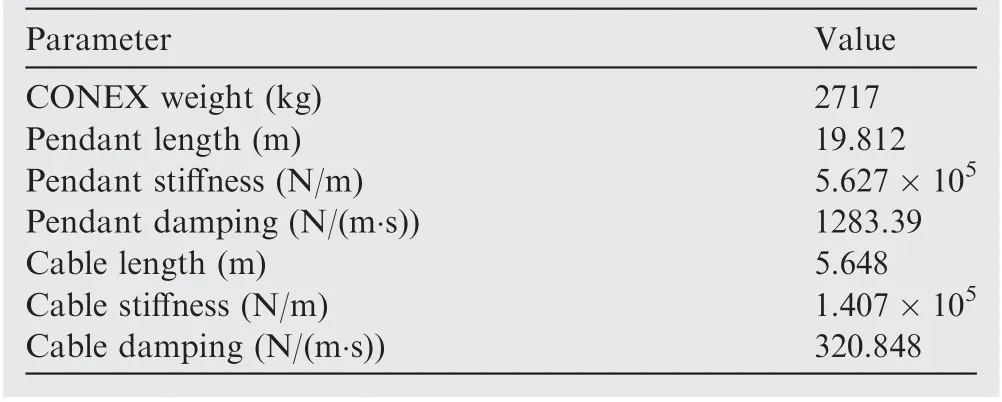
Table 1 Basic parameters of CONEX container.
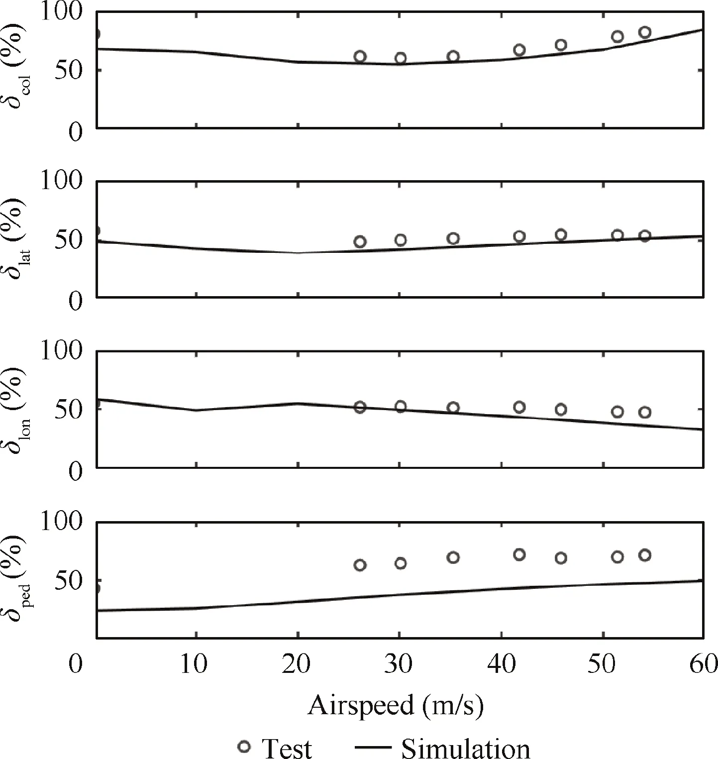
Fig.2 Trimmed control characteristics of UH-60 helicopter with CONEX slung load.
3.Formulation and solution of aerial slung load release problem
3.1. Problem formulation
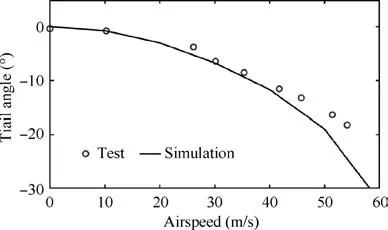
Fig. 3 Trimmed trail angle characteristics of UH-60 helicopter with CONEX slung load.
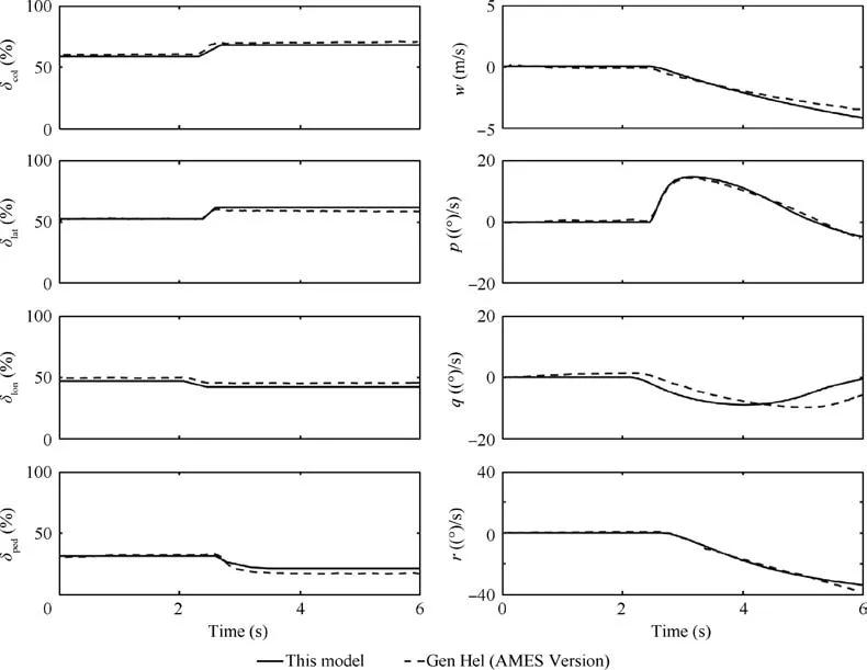
Fig. 4 On-axis transient step response characteristics of UH-60 helicopter in hover.
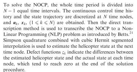
In accurate aerial delivery missions, the helicopter slung load system is assumed to be under steady-hover condition before the release. Since the release is intentional, the pilot response delay time is neglected in this circumstance. The subsequent control procedure can be defined as the stabilization of the helicopter, satisfying state limitations and control restrictions.The problem in nature is to find the optimal control history and the corresponding state trajectory from the initial state to the final equilibrium state. The problem can be solved by the optimal control method, similar to the descriptions of Chi,17Yan,18Meng,19Wang20, and Betts.21
According to the optimal control theory,a NOCP is formulated, consisting of state equations, initial boundary conditions, path constraints, terminal constraints and an objective function. Since the whole optimization procedure is after the release of the slung load, the states of the slung load are no longer considered.
To study the displacement of the helicopter after the release, the final translation deviation relative to the initial position, RH= X,Y,Z[ ]T, is added into the states:
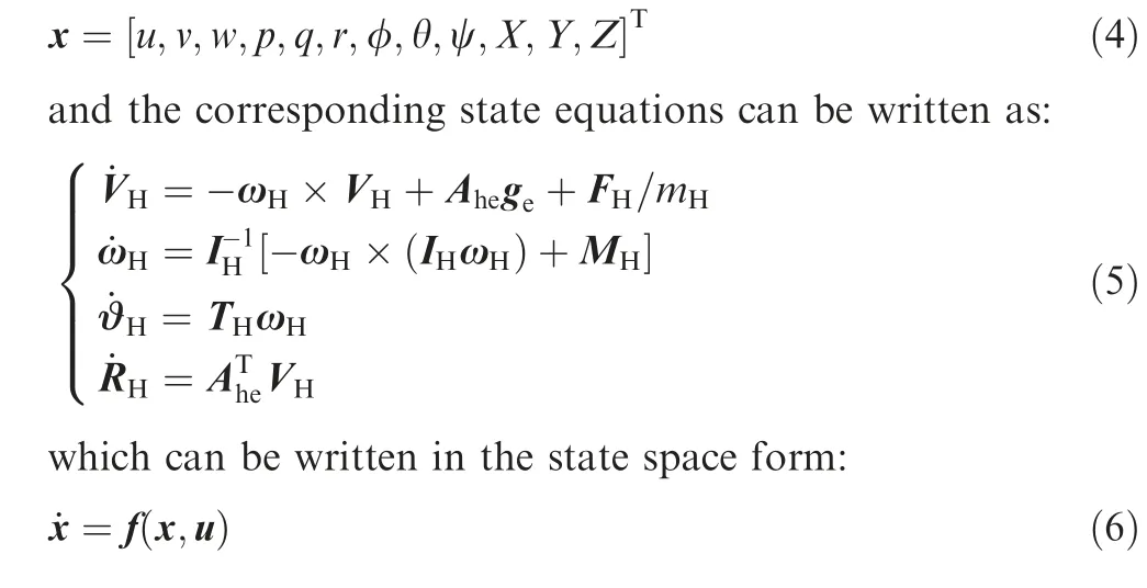
The objective function can be written as:

where the two scalar functions, Φ and L, are related to the boundary conditions and path variables respectively.
In the determination of the objective function,firstly,it will be better if the pilot can stabilize the helicopter in a shorter time such that the final time should be included in the objective function. In addition, since the object of the study is a piloted helicopter, the workload should be considered to avoid too aggressive manipulations. In some cases, if the pilot hopes to maintain the position of the helicopter after the release, the final state deviations should be taken into account. Hence,the objective function is multi-objective22and the two scalar functions in Eq. (7) can be written as:

Here, w*(* being the symbol for all subscripts) is the weight coefficient of the corresponding term in the objective function.Wris a diagonal 12-dimentional matrix whose diagonal elements are weight coefficients of related helicopter states. A specific term can be neglected by setting the related weight coefficient to zero. The subscripts 0 and f denote the initial moment and the terminal moment respectively. The physical domain of time, t ∈0,+∞[ ), is mapped to the computational domain of time, τ ∈-1,1[ ), with the transformation of:

The weight coefficients in Eqs. (8) and (9) and are determined through a large number of simulations, from which some variation characteristics are obtained which will be discussed Pin Section 4 based on the simulation results.
The initial boundary conditions xcan be obtained through statically trimming the helicopter slung load system model and selecting the trimmed state variables related to the helicopter. Thus, the initial boundary conditions can be written as:

The path constraints are limitations during the whole control procedure as shown in Table 2. Velocity, angular velocity and attitude ranges are selected by experience, considering safety-related requirements and helicopter performance limits.The control rate range is determined by both experience and trials, concerning actuator maximum physical rate limits and the feasibility of the NOCP. Detailed descriptions of trials for determination of the control rate range can be found in Section 4.1. Parametric analyses of the control rate range of optimization results are presented in Section 4.3. Ranges in Table 2 are scaled to near -1 to 1 by multiplying the normalization factor to speed up the computation and help with numerical convergence.
The terminal constraints are selected to be the steady flight condition of the helicopter, which can be written as:

3.2. Problem solution procedures
The total constraints of the NLP can be written as:
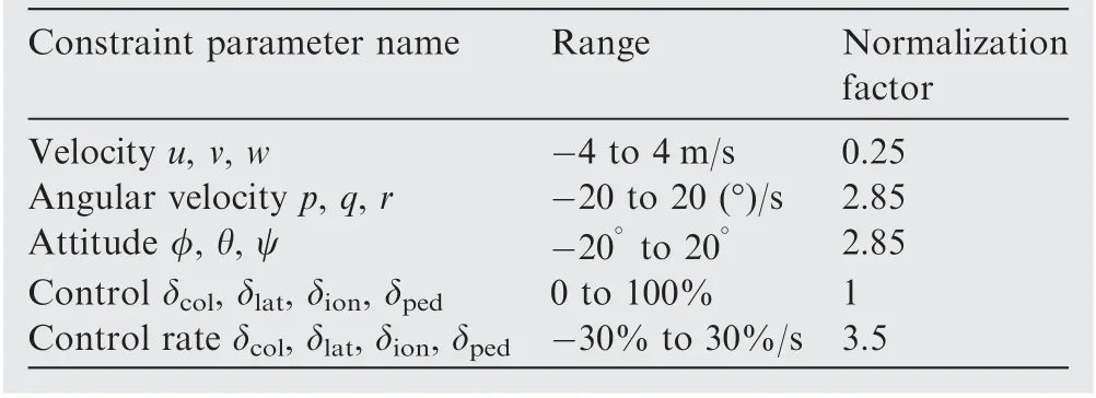
Table 2 Path constraints of trajectory optimization problem after slung load release.
Finally, an SQP method is adopted to solve the obtained NLP (Eqs. (13) and (14)), which is of good robustness and computational efficiency.
4. Optimization results and analyses
4.1. Objective function determination procedure
Owing to the lack of a unified method for the determination of the weight coefficients in Eq. (15), a large number of trials are performed to study the variation laws of the optimization results caused by different weight coefficient assignments.The control rate constraints are loosened temporarily to-60%~60%/s to avoid optimization procedure failure.Firstly,since it is obvious that the control time is an important aspect to consider, the result of minimizing the control time is set as the baseline of the study,which is Case 1.Then,different terms are added to the objective function to study the contributions of different terms to the results and the variations of the results due to changes of the corresponding coefficient.At last, in combination with the obtained rules of the term influences, final configurations of the objective function are determined.
For all the trials,the initial states are steady hovering of the helicopter slung load system.Since the release of the slung load is determined by the pilot,there is no delay between the release and the subsequent controls for stabilization. In this case, the hover state in Fig.2 is set as the initial state of the subsequent optimization procedure to generate the optimal control history from the initial state to the final equilibrium state.
Case 1 minimizes the control time for stabilization.The corresponding objective function is:

Case 2 is related to the circumstance considering simultaneously the control time and pilot workload. As is shown in Fig. 5, it is assumed that all 4 weight coefficients related to the control rates are 0.25; that is, the workload from different controls are equal to each other. The optimization results related to different wp,wtconfigurations are calculated.
It can be observed from Fig. 5 that, with the gradual decrease and increase of the time weight wtand the pilot workload weight wp, respectively, the control history becomes smoother and control amplitudes smaller,with longer required control time. However, despite the increased control time, the total time for stabilization is still shorter than 2.5 s, which is acceptable. From the longitudinal control history figure δlon,we can find that the increase of the workload weight can reduce the workload of the longitudinal control significantly,which is beneficial to safety.Thus,the time weight can be smaller than the workload weight. However, from many trials, we find that the NOCP can be infeasible if the time weight is too small.That is,the path constraint parameter ranges,in particular the control rate range, in Table 2 should be enlarged for the convergence of the NOCP. Since the control rate range is usually limited according to experience,the time weight should not be set too small.
By comparing the control histories in Fig. 5, we find that the collective and longitudinal controls are larger than the other two controls; thus the weights of the collective and longitudinal controls can be set larger than the other two control weights. The objective function of Case 2 is determined as:

Case 3 corresponds to the circumstance when the pilot has requirements on the final vertical translation deviation relative to the initial position. The workload weight is set as zero initially to highlight the effects of the final state deviation weight wron the optimization results. Fig. 6 presents the results related to vertical translation. From the w and Z graphs in Fig. 6, we find that when wr<0.3, with the growth of wr,the positive part of the vertical velocity becomes more significant and the final vertical translation deviation becomes smaller. However, when wr>0.3, the increase of the final state deviation weight has little effect on the results.Thus,wrshould be set large enough in the final determination of the objective function.
From the collective control history in Fig.6,it is found that the general variation rule of the collective control is to decrease first and then increase. The initial decrease is to decelerate the upward velocity until the downward velocity is obtained,eliminating the initial upward translation. The aim of the subsequent increase of the collective control is to decelerate the downward velocity to achieve equilibrium. The increase of wrwill bring forward the corner point and bring about more characteristics of the collective control. Meanwhile, it can be observed that the increase of wrhas little effect on the length of control time.Thus,wrshould not be set too large in the final determination of the objective function.
According to the previous analysis in Case 2, the time weight can be set relatively smaller than the other weights because it brings acceptable increase of time spent. In that case, the time weight is fixed as 0.05 to study the effect of wr,wpon the optimization results. As is shown in Fig. 7, with the increase of wrand decrease of wp, the positive part of the vertical velocity w becomes more significant. Meanwhile, the final vertical translation deviation becomes smaller and the collective and longitudinal controls reach the extreme point earlier. However, the time spent increases first and then decreases because the final state deviation makes no difference if wris too small. In addition, when wr=0.7 and wp=0.25,the final vertical translation deviation is almost zero, thus requiring no larger wr.
Based on the analysis and the obtained rules, the objective function of Case 3 is determined as:

4.2. Analysis of optimization results
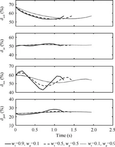
Fig.5 Optimal control time histories of different assignments of time weight wt and pilot workload weight wp.
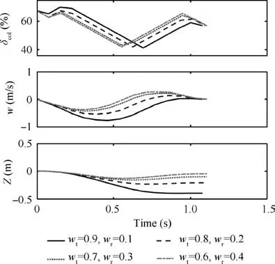
Fig. 6 Optimal control and vertical translation time histories of different assignments of time weight wt and final state weight wr.
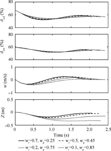
Fig. 7 Optimal control and vertical translation time histories of different assignments of final state deviation weight wr and pilot workload weight wp with time weight wt equal to 0.05.
Fig. 8 presents the optimal control time histories in the three circumstances. The time spent for Cases 1, 2 and 3 is 1.4, 2.1 and 2.1 seconds,respectively, which means that the additional consideration of the pilot workload will increase the control time, while the final vertical deviation requirements have little effect on the time spent.
In Case 1,the pilot has to correct all the controls with high frequencies, which is unpractical. Thus, although the helicopter can be stabilized in the shortest time,the corresponding control history is not a good reference for the pilot.
In Case 2, after the additional consideration of the pilot workload, the control history becomes smoother and simpler.The optimal control history can be summarized as: the collective control decreases (below the collective level) to 5% below the equilibrium value in the first 1.5 s, fast followed by slow,and then increases gradually (pulling up) to the equilibrium value during the remaining 0.6 s; the longitudinal control shares the similar change rule as the collective control, which pushes forward and then pulls back the control stick;few fluctuations can be found in the lateral control and pedal displacement. In this case, it is assumed that the pilot only needs to change these two controls linearly from the initial values to the final equilibrium values.
In Case 3,after the additional consideration of the final vertical translation deviation,the collective and longitudinal controls experience significant fluctuations, while the lateral control and pedal displacement have few changes similar to those in Case 2, which means that these two controls share the same control rule as that in Case 2. For the collective and longitudinal controls, more characteristics can be observed.The collective control decreases quickly to 7%below the equilibrium value in the first 0.7 s,increases to 3%above in the following 1 s, and then decreases to the equilibrium value in the remaining 0.5 s.The longitudinal control shares the similar control rule with the collective control, but with smaller amplitudes and later peak and nadir time.
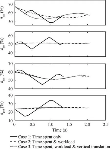
Fig. 8 Optimal control time histories of different objective function configurations.
Fig. 9 presents the corresponding translation trajectories with the optimal control histories of the three cases.In general,the amplitudes of the longitudinal and lateral translation are small;however,the amplitude of the vertical translation is relatively large, because the helicopter slung load system is in hover under the initial condition without longitudinal or lateral velocities. Thus, no longitudinal or lateral aerodynamic forces need to be balanced. The main rotor lift equals the approximate sum of the helicopter weight and the slung load weight at the beginning. Right after the release, the stretch force on the slings acting on the helicopter disappears immediately. Since the main rotor lift now only needs to balance the weight of the helicopter to stay in hover, excessive lift is provided by the main rotor, bringing upward acceleration.
Combining the collective control history in Fig. 8, we can observe from the w and Z graphs in Fig. 9 that the helicopter accelerates the climb initially in all three cases, bringing upward velocity. To reduce the upward velocity (negative w)to zero, the upward acceleration should be eliminated at first,requiring decrease of the collective control to the equilibrium value. Then, the collective control should be decreased more to decelerate the upward velocity. For Cases 1 and 2, the collective control should then be increased gradually to the equilibrium value to avoid downward velocity. However, during the control period, the helicopter has been climbing and will move upward for 0.5 m in Case 1 and 0.8 m in Case 2. For Case 3, the collective control needs further decrease to obtain downward velocity (positive w) to compensate the initial upward translation till the upward velocity reaches zero.Then the collective control should be increased to above the equilibrium value to decelerate the downward velocity and decrease gradually afterwards to zero and avoid upward velocity.
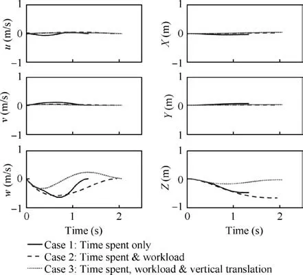
Fig. 9 Optimal translation time histories of different objective function configurations.
Fig. 10 presents the corresponding rotation trajectories with the optimal control histories of the three cases.In general,the amplitude of the pitching motion is larger than that of rolling and yawing motion because the hook point is on the symmetric longitudinal plane of the helicopter, such that the release of the slung load brings little additional rolling moment,thereby leading to no significant rolling motion.Similarly, the release causes little yawing moment, thus bringing about no significant yawing motion. However, since the hook point is in front of the gravity center, the release will cause additional pitching moment, resulting in obvious pitching motion. Another finding is the relatively smaller rolling and yawing change amplitudes in Cases 2 and 3 than those in Case 1 because the lateral control and pedal displacement have few changes in Cases 2 and 3,contrary to their significant changes in Case 1 where apparent changes in the corresponding on-axis response, rolling, and yawing are caused.
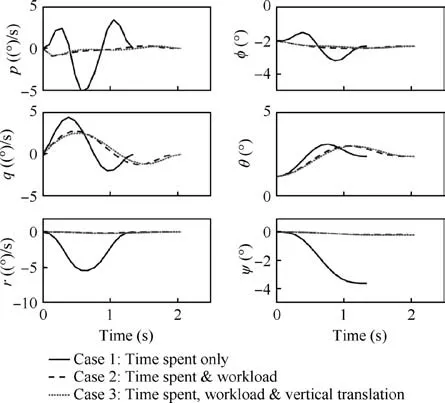
Fig. 10 Optimal translation time histories of different objective function configurations.
The q-graph in Fig.10 appears because the hook point is in front of the gravity center, and the nose-down pitching moment disappears brought by hook force when the sling force disappears. In this case, the helicopter will accelerate the nose-up pitching motion, which requires pushing forward the longitudinal stick for stabilization.Combining the longitudinal control history in Fig. 8, we can observe in Case 1 from the q and θ graphs that, with the rapid increase-decreaseincrease variation in the longitudinal control history,the pitching motion experiences accelerating nosing up, decelerating nosing up, accelerating nosing down and decelerating nosing down in a short time and reaches zero at last.The change rules of the pitching motion in Cases 2 and 3 are the same in nature as that in Case 1 with smaller amplitudes and longer time spent. Additionally, the pitching motions of Cases 2 and 3 are almost the same despite their differences in the longitudinal control histories. This is due to the controller mixer of UH-60A which changes the longitudinal control linearly with respect to the collective control. Thus, the longitudinal pitch on the swashplate is the summation of pilot control and controller mixer output,leading to obvious changes of the longitudinal control.
From the r and ψ graphs (yaw motion) in Fig. 10, we can find that the final yaw angles in all three cases do not equal zero, with 4 degrees in Case 1, smaller than 1 degree in Cases 2 and 3 because the main rotor torque is large initially,requiring larger pedal displacement for balancing. Then, with the decrease of the collective control,the torque decreases simultaneously, leading to excessive left turn moment; thus the helicopter will turn left (negative r). However, since the helicopter slung load system is in hover both at the beginning and at the end, this characteristic has little practical effect.
According to the analysis above, Case 1 is too aggressive,hence unacceptable. Case 2 is the most common choice with a smooth control history, acceptable time spent and a mild state history. Case 3 is the choice for special circumstances.In this paper, this case is chosen only when the pilot hopes to maintain the altitude.
4.3. Parametric effect analysis on optimization results
In this section,the effects of the control rate constraint and the FCS on the optimization results are examined. Since Case 2 is the most common choice, it is chosen as the baseline of the parametric effect analysis. However, the time weight and workload weight are changed to 0.2 and 0.8 respectively to increase robustness of the NOCP,such that the objective function can be written as:

Three control rate ranges are compared in the parametric analysis, which are -30%-30%/s, -10%-10%/s and -5%-5%/s,respectively.As is shown in Fig.11,with the control rate constraint growing more stringent, more time is required for stabilization. From the left most column of the control histories, we can find that the collective control history experiences a straight decline when the control rate ranges are-10%-10%/s and-5%-5%/s.This is because the decline rate of the collective control reaches the maximum in these two circumstances to decelerate the upward movement quickly. Since the collective stick decreases more slowly with a narrower control rate range,the corresponding on-axis response and vertical motion undergo slower deceleration. As a result, the helicopter tends to have more vertical translation deviation, as is illustrated in w and Z graphs in Fig. 11.
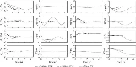
Fig. 11 Optimization results of three control rate ranges.
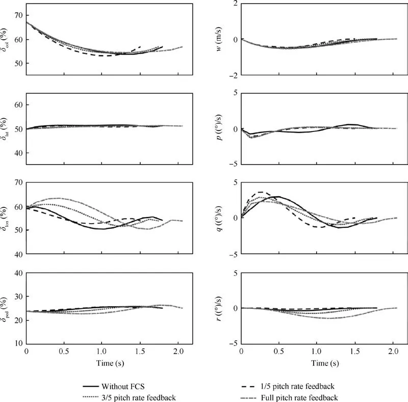
Fig. 12 Optimization results with and without flight control system.
Moreover, the lateral and pedal controls experience more significant fluctuations with a more stringent control rate constraint; however, the longitudinal control becomes smoother.Thus, the corresponding on-axis responses exhibit the same tendency. That is, the roll and yaw motion becomes sharper,while the pitch motion grows smoother. This phenomenon can be explained as follows. First, the collective control decreases while the pedal control maintains the same value initially. Since the decrease of the collective control causes a decrease in the torque, the tail rotor provides more antitorque than needed if the pedal control holds. The helicopter tends to turn left, as is shown in the r and ψ graphs in Fig.11.Then,the pedal increases to reduce the tail rotor pitch to balance the moment. The lateral control fluctuates during the control history to stabilize the rolling motion. Because of the strong coupling among control channels for a helicopter,the decrease in the collective control and longitudinal control causes rolling instability, requiring the lateral control for balance. Different from the lateral control, the longitudinal control history has fewer changes with a more stringent control rate constraint. Since the helicopter has a larger pitching moment of inertia than rolling,the pitching motion has a smaller acceleration than the rolling motion. Due to the extended time spent, the strong pitching damping and the pitching motion can be stabilized softly and slowly,such that the longitudinal control requires fewer corrections.
To figure out the effects of the FCS on the optimization results, a simplified FCS is implemented in the system model with a low-gain rate and attitude feedback loops on roll,pitch and yaw as described by Mansur and Tischler.23As illustrated in Fig. 12, the optimization results without the FCS are compared with the three versions of FCSs. Since the longitudinal control has the most significant change after implementing the FCS, the pitching rate feedback gain is varied to be 1/5,3/5 and full of the value by Mansur. The phenomenon can be generalized that, with a larger pitching rate feedback gain,there will be longer time spent, a sharper longitudinal control history and a milder pitching history. This means that if the damping of the helicopter is increased, more corrections are required in the longitudinal control. Additionally, we can observe that, when the rate gain is 1/5 of the Mansur value,the time spent is shorter than in the circumstance without the FCS. Meanwhile, the longitudinal control is milder and the pitching motion is sharper. Therefore, if the stiffness of the helicopter is increased with less damping, there will be a milder control history,shorter time spent but sharper pitching motion.
5. Conclusions
Optimal control histories and corresponding state trajectories of three different cases are obtained and analyzed in this paper,with Case 1 considering time spent only, Case 2 considering time spent and pilot workload, and Case 3 considering time spent, pilot workload and final vertical translation deviation.Effects of weight coefficient assignments on the optimization results are studied to determine the final configuration of the objective function of each case. Typical characteristics of the optimal control after slung load release in hover are generalized and summarized for the reference of the pilot. Effects of path constraint ranges and the FCS on optimization results are examined for path constraint determination and control system design. Thus, it is possible to provide an operation guidebook for external slung load operations and a complete guidebook could be accomplished referring to the example detailed in this paper.
(1) In Case 1, the helicopter can be stabilized within 1.5 s;however, the obtained optimal control history is too complicated for a pilot and thus unacceptable. In Case 2, the control history is smoothened and the time spent is about 2.1 s,which is a common choice in most circumstances. Case 3 can be chosen only if the pilot hopes to maintain the vertical position after the release. In this case, controls will be more aggressive with little change in the time spent.
(2) In the determination procedure of the objective function, we find that the weight of time spent can be set smaller to avoid aggressive controls. The larger the workload weight, the smoother the control history,and the longer the time spent even if the time weight is fixed. The final vertical deviation weight should be set large enough to be effective but not too large since the effect reaches the plateau when the corresponding weight equals 0.3.
(3) After the release,the pilot should decrease the collective control to be slightly smaller than the equilibrium value,fast followed by slow,and then increase it to the equilibrium value. If maintenance of a vertical position is required, the collective control should be decreased more to generate a downward velocity to compensate the upward displacement and then increase more to eliminate the downward velocity. Longitudinal control shares similar control rules as the collective control while other controls with few changes can be changed linearly from the initial value to the equilibrium value.
(4) If the control rate constraint is strong enough, the collective control undergoes a straight decline with the maximum value equal to the initial constraint.The more stringent the control rate constraint, the longer the time spent,the more changes in the lateral and pedal controls but the fewer in longitudinal controls. On-axis response histories experience the same variations as the corresponding controls.
(5) The FCS affects the longitudinal control and the corresponding on-axis pitching motion. With the FCS, if the helicopter stiffness is strengthened and the damping is weakened, the longitudinal control will be smoother while the pitching motion will be sharper, and vice versa.
Declaration of Competing Interest
The authors declare that they have no known competing financial interests or personal relationships that could have appeared to influence the work reported in this paper.
Acknowledgements
This study was supported by the National Natural Science Foundation of China (Nos. 11672128) and A Project Funded by the Priority Academic Program Development of Jiangsu Higher Education Institutions.
 CHINESE JOURNAL OF AERONAUTICS2021年2期
- CHINESE JOURNAL OF AERONAUTICS的其它文章
- Recent active thermal management technologies for the development of energy-optimized aerospace vehicles in China
- Electrochemical machining of complex components of aero-engines: Developments, trends, and technological advances
- Recent progress of residual stress measurement methods: A review
- Micromanufacturing technologies of compact heat exchangers for hypersonic precooled airbreathing propulsion: A review
- Towards intelligent design optimization: Progress and challenge of design optimization theories and technologies for plastic forming
- A combined technique of Kalman filter, artificial neural network and fuzzy logic for gas turbines and signal fault isolation
