Whole-process design and experimental validation of landing gear lower drag stay with global/local linked driven optimization strategy
Chengwei FEI, Hotin LIU, Zhengzheng ZHU, Liqing AN, Sholin LI,Cheng LU,*
a Department of Aeronautics and Astronautics, Fudan University, Shanghai 200433, China
b School of Aeronautics, Northwestern Polytechnical University, Xi’an 710072, Xi’an, China
c Department of Mechanical Engineering, North China Electric Power University, Baoding 071003, China
d School of Energy and Power Engineering, Beihang University, Beijing 100083, China
e Beijing Key Laboratory of Aero-Engine Structure and Strength, Beijing 100083, China
KEYWORDS Global/local linked driven optimization;Landing gear;Lower drag stay;Optimization;Whole-process design
Abstract Landing gear lower drag stay is a key component which connects fuselage and landing gear and directly effects the safety and performance of aircraft takeoff and landing. To effectively design the lower drag stay and reduce the weight of landing gear,Global/local Linked Driven Optimization Strategy(GLDOS)was developed to conduct the overall process design of lower drag stay in respect of optimization thought. The whole-process optimization involves two stages of structural conceptual design and detailed design. In the structural conceptual design, the landing gear lower drag stay was globally topologically optimized by adopting multiple starting points algorithm.In the detailed design,the local size and shape of landing gear lower drag stay were globally optimized by the gradient optimization strategy. The GLDOS method adopts different optimization strategies for different optimization stages to acquire the optimum design effect. Through the experimental validation, the weight of the optimized lower dray stay with the developed GLDOS is reduced by 16.79% while keeping enough strength and stiffness, which satisfies the requirements of engineering design under the typical loading conditions. The proposed GLDOS is validated to be accurate and efficient in optimization scheme and design cycles.The efforts of this paper provide a whole-process optimization approach regarding different optimization technologies in different design phases, which is significant in reducing structural weight and enhance design tp wid 1precision for complex structures in aircrafts.
1. Introduction
As one key component, landing gear lower drag stay is adopted to connect fuselage and landing gear in aircrafts.The design of lower drag stay directly influences the take-off,ground maneuvers and landing safety of aircrafts.1From the strength perspective, it is required to enhance the strength,enlarge the bearing-capacity by increasing the sizes of the lower drag stay. Therefore, it is inevitably to overmuch rise the costs. From the lightweight perspective, it is reasonable to reduce the sizes for the sake of lightening the weight of aircrafts and decreasing the costs.2Obviously, the strength and weight related to sizes are a pair of contradiction in the design of lower drag stay.The traditional design of landing gear lower drag stay is to reserve a larger safety factor to ensure the strength with respect to engineering experience.3Undoubtedly,the design idea increases structural weight and design cost.To balance the two aspects, it is urgent to perform the optimization design of lower drag stay.
Optimization method is the core of structural optimization design. In term of structural optimization, various optimization tools and algorithms have emerged. Xue et al. proposed the new Particle Swarm Optimization(PSO)algorithm to optimize the nose landing gear strut of aircraft.3Yin et al. studied the optimization of the critical unlock force with a constraint on the initial over-center angle, for the locking mechanism of landing gear.4Caixeta and Marques investigated the multidiscipline design optimization of flexible aircraft wings regarding structural and aeroelastic characteristics.5Lee et al.conducted the dynamic response optimization of a joined wing using equivalent static loads.6The works mainly considered the sizes of components instead of other design features.7,8.Meanwhile,the efforts needed to repeatedly perform the optimizations when the optimization layout was modified so that design costs greatly increase.9,10
With the rapid development of optimization technology,more structural features have to be involved in optimization by an integrated manner.11Zhu et al. presented a structural mass prediction method for conceptual design of blendedwing-body aircraft using a structure analysis and optimization method combined with empirical calibrations.12Yang et al.combined automated finite element modeling technique with a ground structure approach to optimize aircraft wing structure.13Deng et al. studied multi-objective design optimization of lightweight thermo-elastic structure.14Lian et al. combined shape and topology method to perform the two-dimensional(2D) design optimization of minimal stress subject to volume constraint.15Similarly,various features were considered in aircraft structures such as aircraft wing,13,16,17fuselage,18–20F35 joint strike fighter,21and pylon,22especially for landing gears.23–26The features obtained by the methods hardly cater for real engineering features such as stiffeners, lugs, holes,and so forth. Most of optimization methods have been employed in aircraft structural design.However,the optimization methods were only applied to one stage of structural design.In this case,it is hard to make the effect of whole structure design reach to the best.Meanwhile,these methods mostly focus on structural weight reduction and computational efficiency, while the machinability of structures were neglected.In other words, the optimization concept did not go through the whole process of structural design. To ensure the effect of landing gear design, it is urgent to consider optimization in many design stages of structural machinability and computational efficiency.
In this paper, a whole-process design optimization approach,i.e.,Global/local Linked Driven Optimization Strategy(GLDOS),is proposed to improve the design of lower drag stay. In the GLDOS, different optimization techniques are adopted under different design stages.In the conceptual design stage,Multiple Starting Points(MSP),a global search method,is adopted to obtain the preliminary optimal layout together with structural processing performance. In the local size and shape optimization stage, the gradient optimization method,a local optimization method, is employed to finish the final optimization design of lower drag stay, by refining the acquired conceptual optimization model.Obviously,the developed GLDOS considers optimization idea throughout the whole design process including globally conceptual design and locally detailed design, to improve the lightweight design of landing gear. In addition, the experiment of a landing gear lower drag stay in aircraft is conducted to validate the developed method.
The rest of this paper is organized as follows. In Section 2,the global/local linked driven optimization strategy (GLDOS)is introduced in the foundation of structuring the engineering problem of landing gear lower drag stay. Section 3 performs the design optimization of landing gear lower drag stay with the GLDOS involving global conceptual design as well as local size and shape design optimizations.The designed landing gear lower dray stay are validated in respect of the experiment data acquired by test system setup in Section 4. Section 5 gives the conclusions in this study.
2. Problem and method
2.1. Problem formation
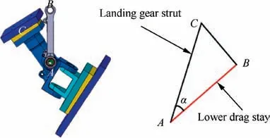
Lower drag stay is a link mechanism in landing gear system of aircraft,to connect aircraft fuselage and strut by bearings and drive the landing gear for extension or retraction.1,27The sketch map of lower drag stay in landing gear system is illustrated in Fig. 1.
In respect of the work precinple of landing gear system,when the landing gear bears ground load, the lower drag stay moves upward due to the restraining effect of locking stay,and the rotational degree of freedom of lower drag stay connecting bolt is restrained.Hence,the lower drag stay can be considered as bearing rod. The design of lower drag stay requires the structural weight reaching to the lightest under satisfying the requirements of static strength and overall structural stiffness.Obviously,the design of the lower drag stay directly influences the take-off,ground maneuvers and landing safety of aircrafts.
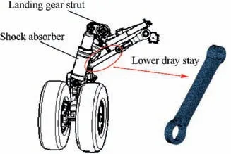
Fig. 1 Strut and lower drag stay attitude angle of landing gear system.
Generally, the strength and weight related to sizes are two main factors, i.e., a pair of incompatible contradiction, in the design of lower drag stay. The traditional design of landing gear lower drag stay is to ensure the strength by reserving a larger safety factor with respect to engineering experience.3However, this design idea undoubtedly increases the structural weight and design cost. Therefore, it is urgent to perform the optimization design of lower drag stay by developing an efficient optimization method. The use of the previous optimization methods only focusses on one design stage to reduce structural weight and improve computational efficiency. In the methods, the machinability of structures is neglected and optimization concept does not go through the whole process of structural design.Therefore,this paper attempts to propose a promising optimization approach, i.e., global/ local linked driven optimization strategy (GLDOS), by considering optimization in many design stages to refine the landing gear design. In other words, the optimization thought is absorbed into the whole process of the landing gear design and different optimization strategies are adopted for different design stages such as globally conceptual design and locally detailed designs(i.e., shape optimization and size optimization).
2.2. Global/local linked driven optimization strategy
Generally, the optimization task consists of minimizing the objective function depending on design variables and boundary conditions.28The design optimization model of lower dray stay can be described as fellow:

where f(x)is the objective function with minimum volume fraction under loading;gj(x)is the stress constraint function;hk(x)is the displacement constraint function; x is the vector of design variables;xLis lower bounder of design variable vector;xUis upper bounder of design variable vector.
In this paper, we develop a whole-process optimization design approach,called global/local linked driven optimization strategy (GLDOS), to improve the design of landing gear lower drag stay.The proposed GLDOS considers optimization in different optimization stages involving conception design and detailed design.
In the conceptual design stage, the design of landing gear lower drag stay involves many parameters and complex boundary conditions,so that this design is a non-convex problem. The commonly-used optimization method such as gradient-based methods are susceptible to find local optimum,because the optimized results obtained are dependent on the initial designing starting point. To address this issue, in this study Multiple Starting Points (MSP) optimization,29a new global research algorithm, is adopted to perform the global topology optimization regarding the processing performance of structure, to obtain the preliminary optimal layout (i.e.,configuration) of lower drag stay. This global search MSP algorithm performs an extensive search of the design space for multiple starting points to improve the chances of finding a more global optimum. Being dependent on the initial design starting point, n different design starting points could potentially result in n different optimum solutions. It is also highly likely that different design starting points could result in the same optimum solution. However, this does not mean that the optimum solution found is the global optimum. The schematic diagram of the MSP algorithm is illustrated in Fig. 2.
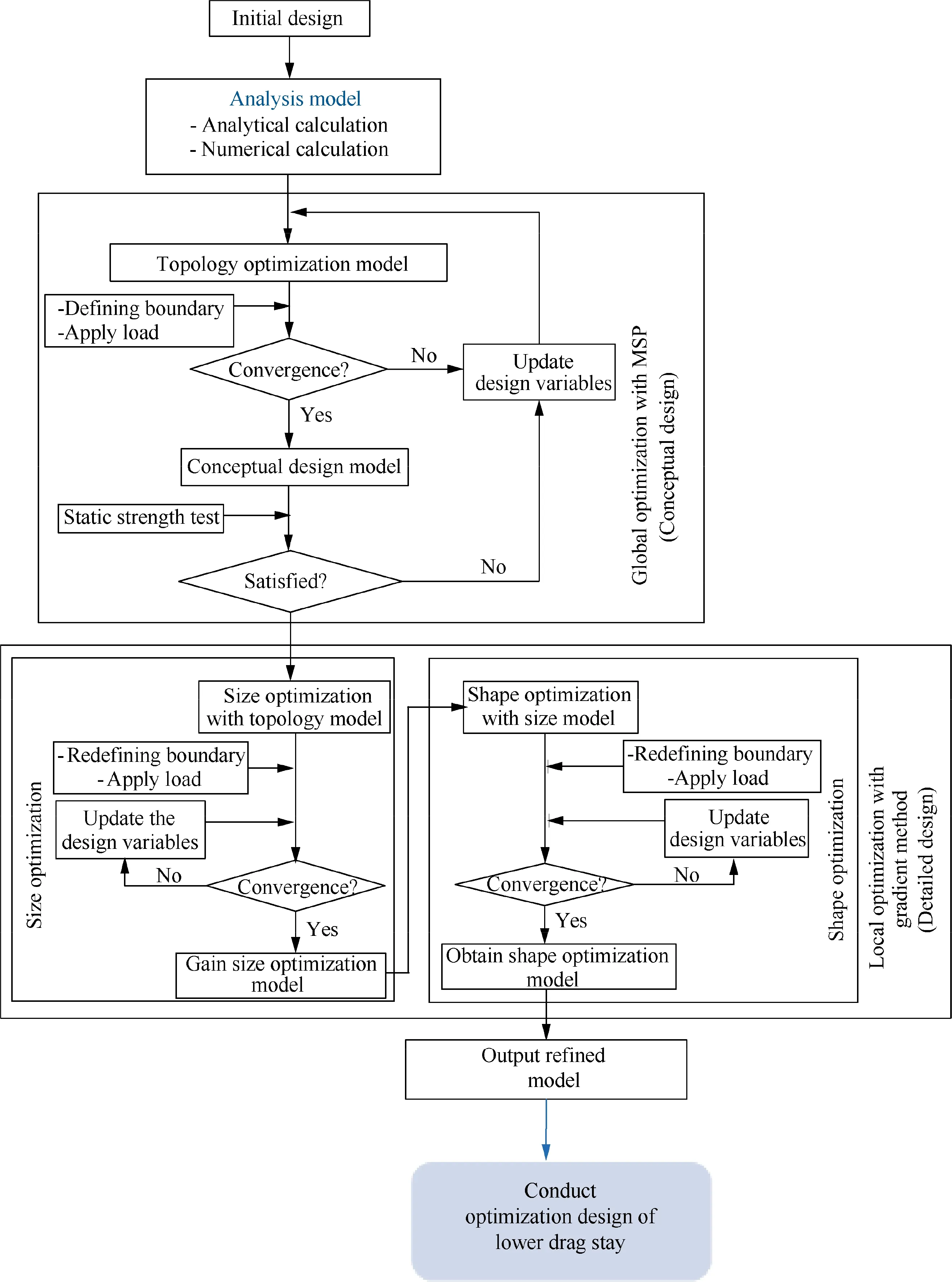
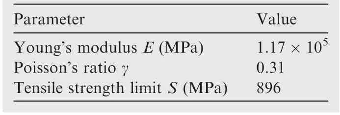
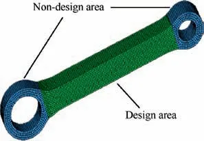
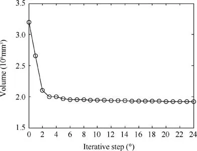
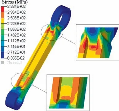
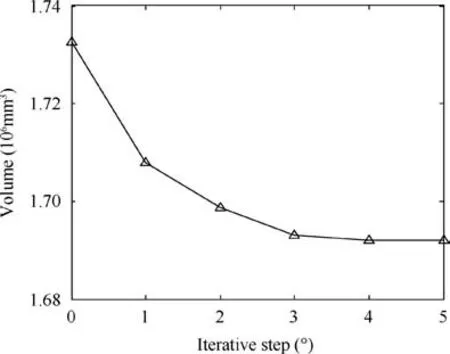
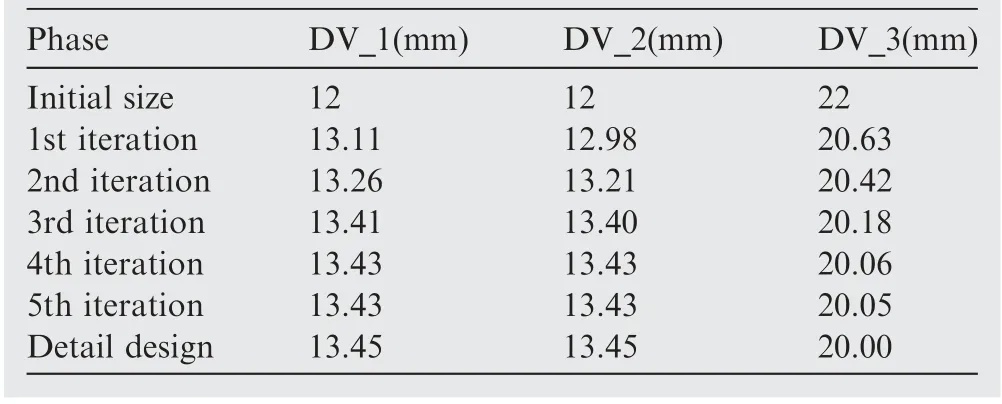
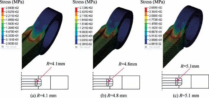
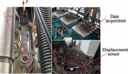
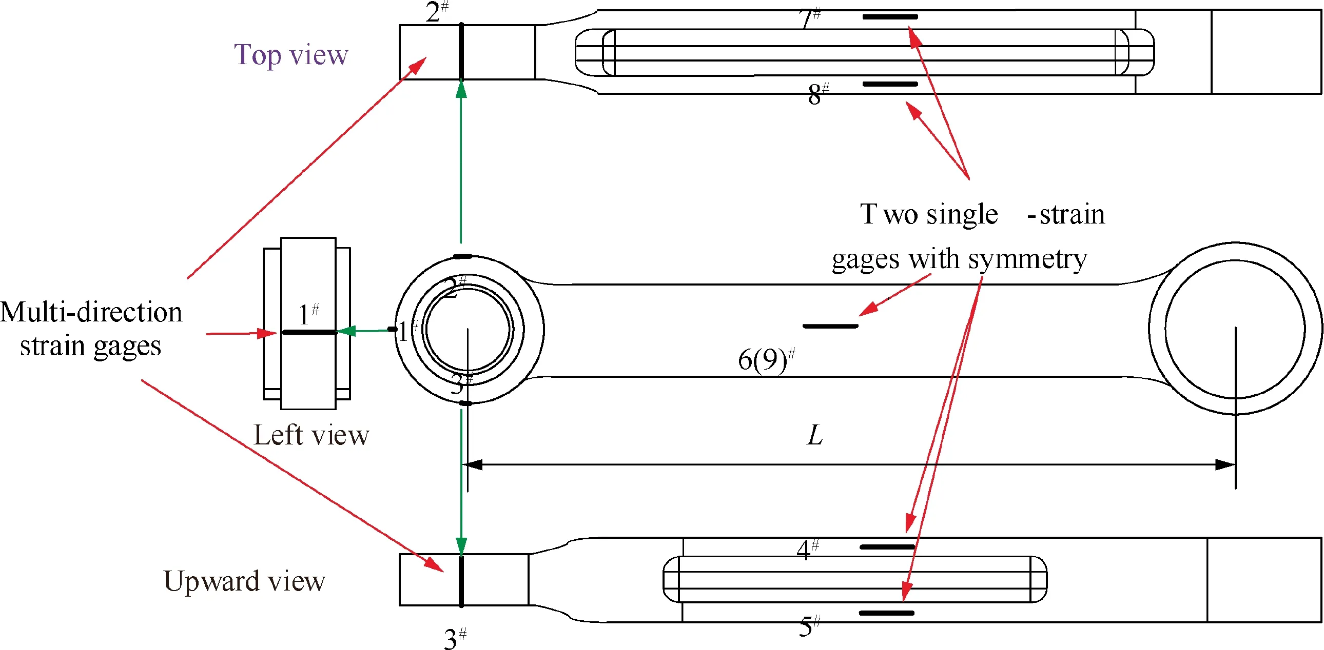
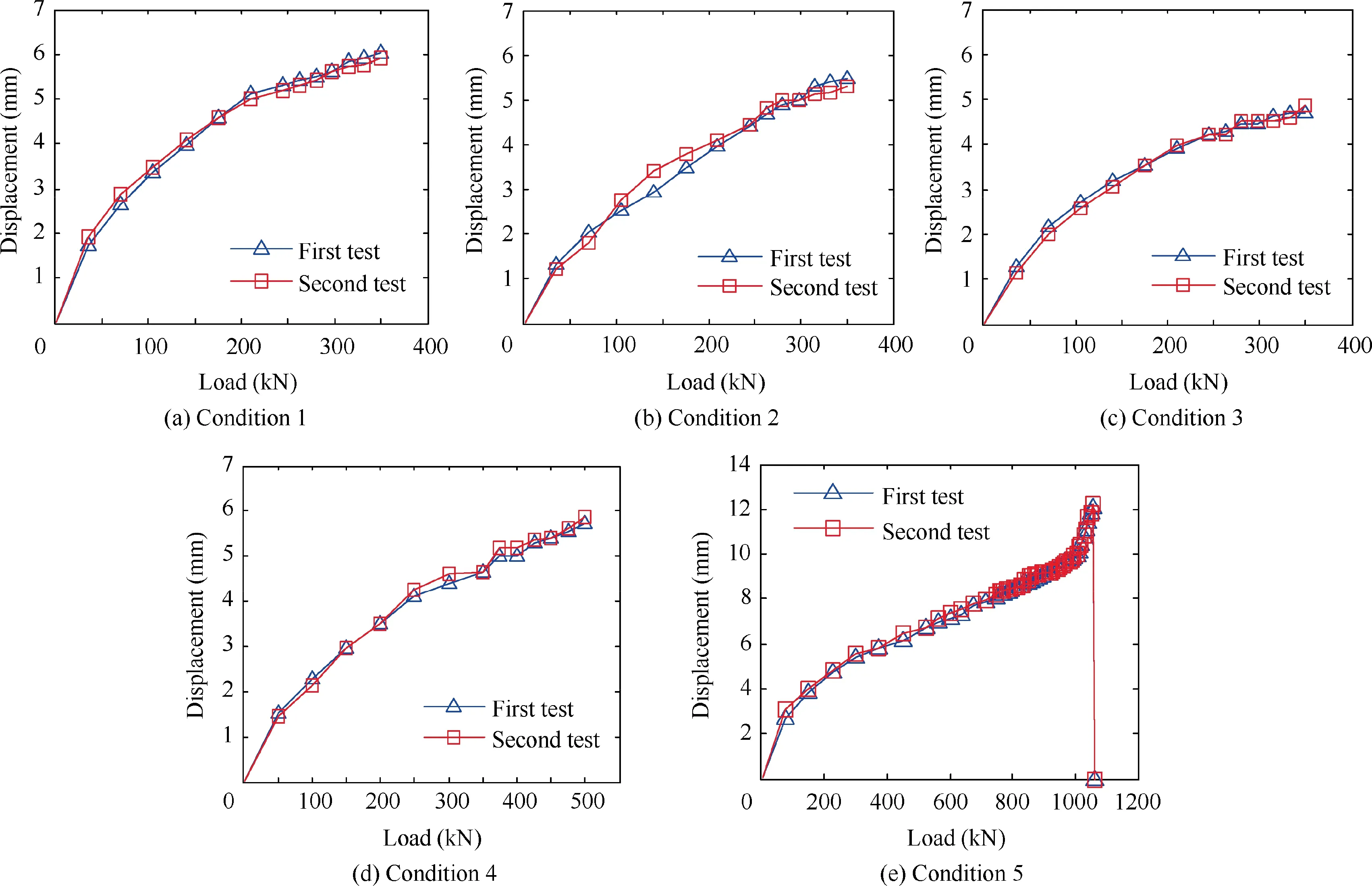
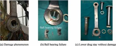
As revealed in Fig.2,the non-convex function is f(x)which is bounded by -a In detailed design stage, more local optimization designs are required. Furthermore, the optimization designs involve less parameters and boundary conditions, and is a relatively simple optimization problem. In this stage, gradient optimization method30is employed to conducted the size and shape design optimizations based on the acquired conceptual model,to gain a more refined lower drag stay model. The size optimization of the lower drag stay is performed on the foundation of topology optimization, to determine the optimal sizes of lower drag stay. To further improve the structural model acquiring from the size optimization, the shape optimization is conducted to refine the structural shapes such as chamfer,turning,smoothness,and so forth and then output the optimal model of the lower drag stay. Obviously,in the developed GLDOS,the optimization idea is respected throughout the whole process of structural design by adopting different optimization techniques, to acquire the perfect structure of lower drag stay and improve the lightweight design of landing gear.It should be noted that all optimizations are finished based the same design variables,constraints and loads. The optimization flowchart of the proposed GLDOS is depicted in Fig. 3. As shown in Fig. 3, the optimization framework based on the GLDOS comprises three modules:analysis model,conceptual design and detailed design. The detailed precedure is described below. Step 1 The initial design data and boundary conditions of landing gear lower dray stay under different loading conditions are determined according to the actual operation conditions. Fig. 2 Schematic diagram of MSP optimization. Fig. 3 Framework of global/local linked driven optimization strategy. Step 2 The global search strategy based on the MSP is used to obtain a preliminary conceptual design model of landing gear lower drag stay based on the topology optimization.Then, the static strength test is carried out to determine whether the model meets the load requirements.If dissatisfied,the topology optimization is re-conducted by modifying the values of design variables and restructuring topology optimization model, or continue to conduct Step 3. Step 3 In the basis of the model obtained from the conceptual design in Step 1,the size design optimization of the lower drag stay is conducted subject to the same design variables and constraints,to define the sizes of lower drag stay and establish the size optimization model. If unconvergent, the size optimization model is updated by modifying the deign variables and redefining the boundary conditions.The action is operated untill convergence and the establishment of the size optimization model. If convergent, continue to Step 4 for shape optimization in the detailed design stage. Step 4 The shape design optimization of the built size optimization model is performed with regard to the design variables and boundary condictions, to refine the model and then acquire the final model of lower drag stay which is optimal and perfect.It should be noted that the gradient optimization method30is employed in the size and shape optimizations. In this section, the optimization design of landing gear lower drag stay is implemented in respect of the developed GLDOS including conceptual design and detailed design mentioned in Section 2. Topology optimization is one conceptual design technique which respects the manufacturing process of structure in the initial stage of product design, when the design space, design objective and constraints are known.The purpose of the topology optimization is to find the optimal material layout and then provide the critical conceptual design scheme for designers. 3.1.1. Finite element model The space position, loading conditions, connection form,material property and boundary condition of lower drag stay are considered as design variables. The material of lower drag stay is titanium alloy TC4. The related material parameters of TC4 are shown in Table 1. The Finite Element (FE) model contains 119 396 tetrahedral elements. Referring to Fig. 1,the attitude angle α between strut and lower drag stay is shown in Fig. 4. To investigate the load-bearing characteristics of lower drag stay, five typical structural loading conditions, i.e., 350 kN, 350 kN, 350 kN, 500 kN and 750 kN, are considered under three attitude angles α(31°,36°,41°)as shown in Table 2.The load is exerted at the point B.It should be noted that loading conditions 5 is a structural destructive case. 3.1.2. Optimization model of conceptual design In the optimization model, design variables are the structural parameters listed Table 1. During the optimization design,the FE model was divided into blue part (non-design area)and green area (design area) as shown in Fig. 5, to gain the optimal structure layout.The displacement and static strength of lower drag stay are restrained by the maximum stress and displacement, respectively. Regarding the lower drag stay materials TC4, the tensile strength limit is 896 MPa and the stress is initially 800 kN according to engineering experience.The point A in Fig. 4 was selected as the displacement point subject to the maximum allowable displacement 10 mm.Besides, the model considers the manufacturing features (i.e.,symmetry and pulling model), to improve the machinability of lower drag stay design.The target of optimization is to minimize volume that is related to the mass, to obtain the lightest lower drag stay. The mathematical model of conceptual optimization design is formatted in Eq. (2). Table 1 Material property of lower drag stay. Fig. 4 Attitude angle between strut and lower drag stay. where fvis the volume function of lower drag stay in which the subscript v stands for volume;ρi(i=1,2,3,...,nk)indicates the relative density of ith material element in design area;ρminis the minimal relative value in elements;nkis the total number of elements; x=(ρ1, ρ2, ρ3,...,ρnk) is the vector of design variables(material relative density); T demotes the stress exerting on the lower drag stay;y expresses the displacement of point A. 3.1.3. Lower drag stay optimization After defining the optimization problem, the MSP method29was applied to the conceptual optimization design of lower drag stay by utilizing many starting points to find the global optimal solution. In this optimization, the topology optimization tends to convergent after 24 iterations. The iteration process is shown in Fig.6.The new topology structure and crosssection shape of the lower drag stay is obtained as shown in Figs. 7 (a) and (b). The preliminary conceptual design model of lower drag stay is drawn in Fig. 7(c). In Fig. 7, we can clearly see the distribution of material and the transfer path of loads. The conceptual design model is re-meshed to conduct the static analysis. The stress nephogram of the lower drag stay is shown in Fig. 8. As revealed in Fig. 8, the maximum stress of lower drag stay is 333.4 MPa at the ends of the stay pole, which satisfies the strength requirement of lower drag stay structure. In this case, we find the maximum displacement is less than 10 mm based on the static analysis,which satisfy the stiffness requirements. On the foundation of the acquired conceptual model,more detailed designs of the lower drag stay are performed by size optimization and shape optimization in coming subsection. 3.2.1. Size optimization Size optimization is to search the optimal sizes of the lower drag stay by updating the properties of structural conceptual model such as thickness of shell elements, stiffness of elastic elements, cross-sectional properties of elements, and so forth.In respect of the concept model of topology optimization,the size optimization of lower drag stay was carried out by meshing the middle surface shown in Fig. 9 and selecting the appropriate design variables, to determine the size optimization model. The FE model and design variables of size optimization are shown in Fig. 9. The loads and boundary conditions of the FE model are the same as these in the topology optimization. The mathematical model of size optimization is shown in Eq. (3). Table 2 Five loading conditions at the point B. Fig. 5 Optimization model of lower drag stay. Fig. 6 Iteration process of conceptual optimization design. in which x indicates the vector of design variables(three sizes:DV_1, DV_2 and DV_3). Fig. 8 Stress contour in conceptual design under dangerous condition. The design variables in size optimization are the thickness of structural element in design area. Based on the experience of engineering design, the distribution characteristics of the thicknesses of three structural elements are shown in Table 3. The gradient algorithm30is employed to find the optimal size combination (the minimum volume) subject to static strength and structural stiffness.The static strength constraints are the area selected reasonably according to the initial size analysis, and the geometric abrupt position is removed. The structural stiffness constraint is the displacement of reference points which was calculated based on the initial size shell element model. The objective of the size optimization is still to minimize the volume of lower drag stay. The initial values of the DV_1, DV_2 and DV_3 are 8 mm, 8 mm and 16 mm,respectively. Through the size optimization, the iteration process is shown in Fig. 10. As illustrated in Fig.10,the volume optimization converges 1.692 mm3after 5 iterations. In the five iterations, the change of design variables (DV_1, DV_2 and DV_3) are listed in Table 4. Fig. 7 Optimization result and concept design result. Fig. 9 FE modeling and design variables. Table 3 Initial value and design regions of size optimization variables. Fig. 10 Iteration curve of size optimization. Table 4 Change of design variables in size optimization. As shown in Table 4, the design variable DV_1 and DV_2 become larger, while the DV_3 becomes small gradually. All the values of the three design variables locate in their corresponding ranges displayed in Table 3. Besides, the volume reaches to the stability after five iterations. In this time, the volume of the lower drag stay is reduced by 2.34%, which is equivalent to the weight reduction of lower drag stay by 2.34%due to the same material.Obviously,the structural sizes of conceptual design were changed through the size optimization so that the 3D model of the optimized region was reconstructed.The structured FE model was meshed to perform the static analysis. The analytical results show that the static strength and stiffness of the design area satisfy the design requirements. Therefore, it is indicated that the mass of the lower drag stay is reduced while keeping the strength and stiffness of structure. 3.2.2. Shape optimization Shape optimization is to optimize the structural shape and position of parts in the detailed design stage, to find the optimum shape,reduce stress concentrations and change the crosssections.Besides,the manufacturing process of the structure is also considered in shape optimization.In this optimization,the design variable is the chamfering R in the middle trench of lower dray stay indicated in Fig.11.The initial value of design variables is R=4 mm, and the chamfering varies from 4 mm to 7 mm. The constraint condition is that stress value is less than 500 MPa. The optimization target is the minimum volume. The mathematical model of shape optimization is illustrated in Eq. (4). After three iteration, the optimization converges and achieves the expected design. The optimization results are shown in Fig. 11. where S is the stress function related to the chamfering R. In Fig. 11, it can be seen that the stress of the chamfering become small from 284.3 MPa to 265.9 MPa when the chamfering R gradually increases from 4.1 mm to 5.1 mm.in respect of processing technic,the chamfering angle R=5.1 mm is the optimum for the shape optimization,because large chamfering make the lower drag stay weight reduce once more. In this section,the experiments of landing gear lower drag stay are conducted to validate the optimization results of landing gear structure design and the effectiveness of the proposed GLDOS method. Fig. 11 Lower dray stay stress changes with different chamfering R. Six single strain gages were installed along the axial direction at the positions of I-beam in the middle part of lower drag stay(i.e., 4#,5#, 6#,7#, 8#and 9#). The three multi-direction strain gages are placed along both the circumference of upper and lower lugs(i.e.,10(3)#,11(2)#and 12(1)#).The position layout of strain gauge is shown in Fig. 12. An electro-hydraulic-servo-universal testing machine(Mode no. YDL2000, Changchun Mechanical Science Institute Company, Changchun, China) was adopted to conduct static test in [0, 2000 kN]. The test device system is shown in Fig. 13. In Fig.13,the experimental data was collected in the range[0, 20 000 με], by multi-channel strain automatic acquisition and processing system (Mode no. DH3816, Donghua Testing Technology Company,Suzhou,China).In the test,the vertical displacements of the lower drag stay and the strut were measured under different loading conditions. The center of lower drag stay lugs was taken as the measuring point A. The detailed experiment procedure of the lower drag stay is described as follows: Step 1: For the test of all (five) conditions, the displacements of the lower drag stay were collected by loading 10 %the test load listed in Table 3, in which the exerted load changed from 0 to 70 % the test load. And then the 5% the test load was added to the stay from 70% to 100% the test load. Fig. 13 Test device system. Step 2: For the first three conditions and Condition 5, the load held 3 s once the load reached to the test load, while the load held 30 s for Condition (4). Step 3:The first four conditions were unloaded step by step,following the inverse process of loading. Step 4: During the test process, the experiment stopped if the test piece was damaged, or continue to the next step. Step 5:Condition 5 was loaded by 1%the test load step by step until 150% the test load, i.e., 1125 kN. Fig. 12 Position distribution of strain gauge on lower drag stay. In respect of the above process and explanation, the experiments were finished twice for five conditions and the data were collected. The test results of the two tests for the five conditions are shown in Fig. 14. In Fig.14,we can see that the test has good repeatability in the curve trend and the experimental matching.It is supported that the test results from the test rig is robust and the test rig can be adopted to validate the developed optimization method(GLDOS). In term of the test procedure described in Section 4.1, the test part(a lower drag stay)is tested under Condition 5 by loading the force from 0 to the damage limit.Through the damage test,it is found that the test part occurs failure when the force reaches to 1065 kN which is 142%of 750 kN.The damage test effects are displayed in Fig. 15. As revealed in Fig. 5, the failure of the test part occurs in Fig.15(a)when the test part is loaded to 1065 kN.In this case,namely,the ball bearings in the lower drag stay are crushed and broken,as shown in Fig.15(b),but the lower drag stay do not occur harmful deformation(shown in Fig.15(c))and miss the bearing capacity during the test. It is indicated that the test is operated within the elastic load limit of lower dray stay. To further support the developed optimization method,the comparison of the method with the traditional design method was done.The test results are summarized as shown in Table 5.Under different loading conditions, the distance between the lug center of lower drag stay (denoted by L in Fig. 12) and the maximum stress of design regions are selected as the objects of comparative analyses. Fig. 14 Load and displacement curves with load under different loading conditions. Fig. 15 Damage test under load Condition 5. Table 5 Precision comparison of GLDOS and tests. As illustrated in Table 5, the errors of the developed GLDOS is far less than these of the traditional method for three optimization objects(parameters)under five loading conditions.Meanwhile,the weight of lower drag stay is reduced by 16.79%,which is more than the traditional method(8.03%).It is indicated that the proposed GLDOS method is validated to be more effective and accurate when the proposed method is adopted in the design of the lower drag stay. Therefore, the application of the proposed method to the structure design of landing gear is very successful. (1) An efficient optimization method, i.e., Global/local Linked Driven Optimization Strategy (GLDOS), by considering optimization thought throughout optimizations for different loading conditions under different optimization stages which comprise both the conception design in global optimization and the detailed design in local optimization. (2) The proposed GLDOS is applied for the design of landing gear lower drag stay in aircrafts, and the optimization results are validated by the comparison of methods and the test data from experimental bench setup. (3) Compared with the traditional design method, the proposed GLDOS method holds better performance in optimization efficiency and weight reduction,by quickly and intuitively guiding structural design. The weight of lower drag stay is reduced by 16.79%. (4) The efforts of this paper provide a promising optimization method for aircraft landing gear design as well as the design optimization of other structures in complex machinery system. Declaration of Competing Interest The authors declare that they have no known competing financial interests or personal relationships that could have appeared to influence the work reported in this paper. Acknowledgements This study was co-supported by National Natural Science Foundation of China (Nos. 51975124 and 51675179), Aerospace Science and Technology Fund of China (No.AERO201937) and Research Start-up Funding of Fudan University (No. FDU38341).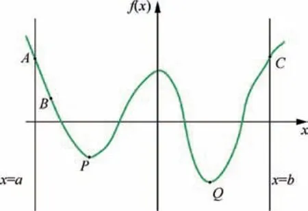
3. Optimization design of landing gear lower drag stay
3.1. Conceptual design

3.2. Detailed design stage





4. Experimental validation
4.1. Experimental setup
4.2. Experiment validation

5. Conclusions
 CHINESE JOURNAL OF AERONAUTICS2021年2期
- CHINESE JOURNAL OF AERONAUTICS的其它文章
- Recent active thermal management technologies for the development of energy-optimized aerospace vehicles in China
- Electrochemical machining of complex components of aero-engines: Developments, trends, and technological advances
- Recent progress of residual stress measurement methods: A review
- Micromanufacturing technologies of compact heat exchangers for hypersonic precooled airbreathing propulsion: A review
- Towards intelligent design optimization: Progress and challenge of design optimization theories and technologies for plastic forming
- A combined technique of Kalman filter, artificial neural network and fuzzy logic for gas turbines and signal fault isolation
