Optimal three-dimensional impact time guidance with seeker’s field-of-view constraint
Shoming HE, Chng-Hun LEE, Hyo-Sng SHIN, Antonios TSOURDOS
a School of Aerospace Engineering, Beijing Institute of Technology, Beijing 100081, China
b Department of Aerospace Engineering, Korea Advanced Institute of Science and Technology, Daejeon 34141, Republic of Korea c School of Aerospace, Transport and Manufacturing, Cranfield University, Cranfield MK43 0AL, United Kingdom
KEYWORDS Applied optimal control;Field-of-view constraint;Impact time control;Missile guidance;Optimal error dynamics
Abstract This paper proposes a new three-dimensional optimal guidance law for impact time control with seeker’s Field-of-View (FOV) constraint to intercept a stationary target. The proposed guidance law is devised in conjunction with the concept of biased Proportional Navigation Guidance(PNG).The guidance law developed leverages a nonlinear function to ensure the boundedness of velocity lead angle to cater to the seeker’s FOV limit. It is proven that the impact time error is nullified in a finite-time under the proposed method.Additionally,the optimality of the biased command is theoretically analyzed. Numerical simulations confirm the superiority of the proposed method and validate the analytic findings.
1. Introduction
The ability to satisfy the desired impact time of anti-ship missiles is often favorable for increasing the survivability since this strategy enables penetrating ship-board self-defense systems by using multiple missiles to intercept a target simultaneously.1–4.For this reason, extensive research activities have been performed to develop impact time control guidance for various guided weapons in recent years.
The first paradigm of impact time control in missile guidance was presented in Ref.1,in which the optimal control theory and linear kinematic model were utilized in deriving the guidance law. The resultant guidance command is given by an optimal form of PNG command with a feedback command that reduces the impact time error. In Ref.5, an guidance law to control impact time, similar to Ref.1, was developed by using the nonlinear engagement kinematics model. Extension of Ref.1was also reported in Ref.6, where the impact angle control constraint was also considered. In this study, the jerk command,i.e.,the time derivative of acceleration,was selected as the control input with the purpose of providing an additional degree-of-freedom for impact time synthesis. Recently,a general approach was proposed in Ref.7to convert existing guidance laws into their impact time control versions. This method can be applied to any guidance law that has a reliable time-to-go estimation. The work in Ref.8analyzed the optimality of error dynamics in impact time synthesis for missile guidance.Different from previous works,the authors in Ref.9suggested a new PNG that relies on a time-varying guidance gain with the purpose of adjusting the interception time gap of multiple missiles.Following the guidance design philosophy proposed in Ref.8,a guidance law to control both impact time and angle was devised in Ref.10. A detailed analysis of the minimum and maximum range of feasible impact times was also investigated in this work.
Impact time control guidance laws have also been developed from the trajectory shaping standpoint. Assuming that a desired Line-of-Sight(LOS)angle profile is a polynomial function, trajectory shaping guidance laws were proposed in Refs.11,12. The impact time constraint in these guidance laws can be satisfied by optimizing the polynomial coefficients.Different from Refs.11,12, a guidance law to control impact time was accomplished in a way to shape the velocity lead angle in Refs.13–15. The advantage of trajectory-shaping-based impact time control is that this strategy does not requires the information on the time-to-go, thus simplifying the implementation.
It is known that impact time control requires to make a detour to adjust the impact time error, which might cause a seeker’s loss of target due to limited FOV constraint. For this reason,it is meaningful to design impact time control guidance laws that not violate the seeker’s FOV condition. The earliest work that considers the seeker’s FOV limit under impact time constraint was reported in Ref.16. This method was based on the switching of guidance command from the original guidance command providing the desired impact time to the guidance command maintaining the constant look angle.This switching strategy, unfortunately, suffers from a sudden abrupt change of the acceleration command. A similar idea was also utilized in Ref.17by switching the guidance gain to cater to the seeker’s FOV limit. To enforce a continuous command, the authors in Refs.18,19proposed a bias type of PNG for controlling impact time and utilized the nonlinearity of cosine function to constrain the seeker’s FOV. The seeker’s FOV constraint was also considered in Refs.15–20through velocity lead angle shaping,but these works fail to address the optimality issue. Note that guidance laws proposed in Refs.15–20ensures a monotonic decrease of the velocity lead angle from the initial point. Therefore, these two guidance laws cannot fully exploit the seeker’s available look angle to achieve a larger desired impact time if the initial lead angle is small.
Notice that most guidance laws providing the desired impact time are studied in a Two-Dimensional (2D) engagement kinematics. In order to fully utilize the synergism effect between horizontal and vertical planes, the authors in Refs.2,4,21–23suggested impact time guidance laws formulated in a Three-Dimensional (3D) engagement scenario for tactical missiles. However, these works never consider the seeker’s FOV limit in designing of guidance laws,thus posing some difficulties in practical implementation. As a remedy, this paper aims to suggest a new optimal guidance law to control impact time while satisfying the seeker’s FOV limit in 3D space. Similar to Refs.1,5,8the biased PNG concept is utilized in deriving the guidance command. More specifically, the proposed guidance command consists of two terms: PNG as the baseline command and the feedback command of impact time error.The error feedback term is determined by utilizing the concept of the optimal error dynamics, developed in our previous work.8A nonlinear function is leveraged to shape the error feedback term, ensuring the boundedness of the velocity lead angle.Theoretical analysis uncovers that the impact time error converges to zero as the time goes and the velocity lead angle constraint is always satisfied the proposed guidance law. By analyzing the optimality of the biased command, a theoretical way to choose the guidance gain is also proposed to guarantee finite and zero terminal guidance command. Up to the best of our knowledge, no 3D impact time control guidance law that considers the seeker’s field-of-view limit is available in the open reference.
The remaining of this paper is constructed as follows. Section 2 provides the problem formulation. The details of the proposed guidance law is presented in Section 3. The theoretical analysis of the proposed method is provided in Section 4.Nonlinear engagement simulations are conducted in Section 5.Finally, the concluding remarks are provided in Section 6.
2. Problem formulation
In this section,the guidance problem to be solved in this study is formulated.To derive the engagement kinematics,four basic assumptions are introduced as follows:
Assumption 1. The target is stationary or slowly moving.
Assumption 2. The missile is treated as a point-mass with an ideal dynamics.
Assumption 3. The missile speed is assumed to be constant.
Assumption 4. The seeker’s look angle is approximated by the velocity lead angle.
Here, it is worth noting that the above assumptions have been widely considered for developing impact time guidance laws for anti-ship missiles: (Assumption 1) A target such as battle ship is slowly moving compared to anti-ship missiles.Therefore, the target speed can be negligible when designing a guidance law. (Assumption 2) Most missile guidance and control systems have been designed using the separated guidance and control structure, based on the fact that the bandwidths of the guidance loop and the control loop are considerably different. In this perspective, the guidance problem can be considered as the kinematics problem with ideal missile dynamics. (Assumption 3) The missile’s speed is typically slowly varying compared to other state variables. Therefore, it could be treated as a piece-wise constant at each time step. (Assumption 4) For typical anti-ship missiles, the angleof-attack and sideslip angle are very small during the endgame.Therefore,the seeker’s look angle can be approximated by the velocity lead angle.
Based on the above assumptions, we consider the engagement geometry in the 3D space, as depicted in Fig. 1. In this figure, the notationrepresents the inertial reference frame for describing the positions of the missile and the target.The relative range between the missile and the target is expressed by the notation R. In Fig. 1, the parameters ϑ and φ,as shown in Fig.1,denote the LOS angles between the missile and the target in the inertial reference frame. To be more specific, ϑ is the LOS angle in azimuth direction, and the φ is the LOS angle in elevation direction. The parameters θ and φ represent the velocity lead angles of the missile in the LOS frame as shown in Fig. 1. θ is the velocity lead angle in pitch direction, and φ is the velocity lead angle in yaw direction. Note that these angles can be calculated using the information of the gimbal angles measured by an onboard seeker,as stated in Ref.24. In Fig. 1, σ represents the total velocity lead angle of the missile in the engagement plane. It can be considered as the heading error to achieve the interception condition for the stationary target.Finally,the notation V represents the missile speed. The nonlinear engagement kinematics in the 3D space can be written as24
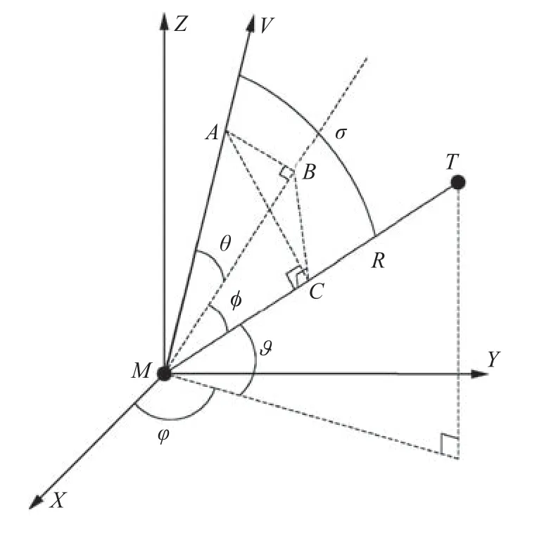
Fig. 1 Three-dimensional homing engagement geometry.
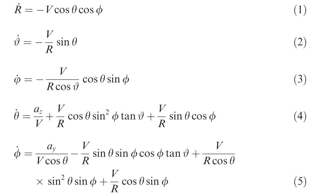
where ayand azrepresent the acceleration components of the missile in yaw direction and pitch direction, respectively.
Additionally,from Fig.1,the relationship between the projected velocity lead angles and the look angle can be determined as follows

The ultimate goal of a guidance is to make the heading error or zero-effort-miss become zero such that the missile can follow the desired collision course to intercept a target.This condition can be mathematically formulated as

where tfdenotes the final impact time.
To enable simultaneous attack against a stationary target,this paper also considers the impact-time constraint, which is given by

where, the notation tfrepresents the final time, and the notation tdrefers to the impact time to be achieved. Here, tdis a kind of design parameter which is selected by a designer to accomplish a mission objective.
In order to maintain target lock-on,i.e.,within the seeker’s FOV limit, the seeker’s look angle should not exceed its maximum permissible value. Under Assumption 4, the seeker’s FOV constraint can be approximated as

where σmaxdenotes the maximum permissible value of the velocity lead angle.
In summary, the problem considered in this study is to devise an optimal guidance law to satisfy constraints Eqs. (7)and (6) without violating condition Eq. (9). It should be pointed out that the desired impact time tdcannot be set arbitrarily large due to the seeker’s FOV limit.With seeker’s FOV constraint Eq. (9), we have -V ≤ ˙R ≤-V cos σmaxfrom Eq.(1). Therefore, the feasible range of achievable impact time under the seeker’s FOV limit can be obtained using the formula, i.e., range over velocity, as

where R0denotes the initial value of the relative range.
Remark 1. Note that the term R0/V cos σmaxin Eq. (10) is a conservative estimation for the achievable impact time as the maximum velocity lead angle cannot be maintained during the flight. However, this information provides some insights into the initial design of the desired impact time.The feasible region of impact time given the interception scenario will be numerically analyzed during simulation studies in Section 5.
3. Impact time guidance law design
In order to intercept the target with the desired impact time td,the concept of biased PNG is utilized in this paper.That is,the proposed guidance command is composed of a baseline PNG part for target capture and a biased command for impact time error regulation.
3.1. Baseline guidance law
The optimal 3D PNG command is given by24

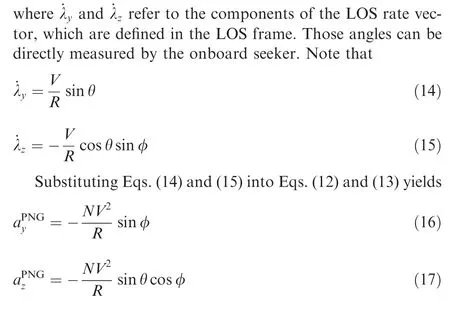
where N indicates the proportional navigation constant of PNG, which is a positive constant. The variable Ω is the LOS rate vector, and V is the missile velocity vector. These vectors can construct the interception engagement plane in the 3D space as mentioned in Ref.25. As the relative range is generally not controllable during the engagement, the PNG command in the 3D space is typically applied in two perpendicular planes which are defined in the velocity frame as24

3.2. Biased guidance command
Extending the results of 2D scenario5to a 3D engagement,the interception time under 3D PNG can be easily determined as
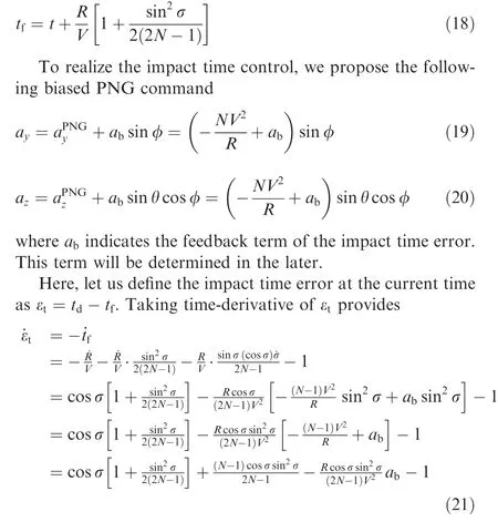
where Eq.(6)is utilized to derive the derivative of velocity lead angle σ.
In Eq.(21),the initial value of velocity lead angle σ is small in practice since the terminal homing guidance phase generally follows a precise guidance handover from a proper mid-course guidance law. The velocity lead angle also gradually decreases as the time goes during the flight. Therefore, the velocity lead angle is kept small during the flight. Hence, we have sin σ ≈σ,cos σ ≈1-σ2/2. By utilizing the small angle approximation of σ and by ignoring the higher-order terms regarding σ,the dynamics of the impact time error as provided in Eq. (21) can be simplified as follows

According to the previous study8,the optimal desired error dynamics for a tracking error e is given as
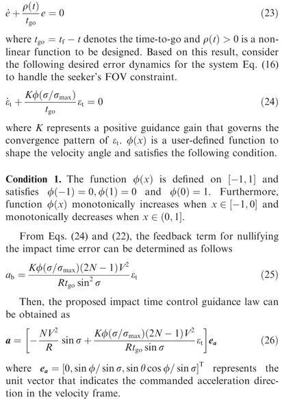
It is clear that the nonlinear functionprovides a way to shape the impact time error feedback command: the capacity in regulating the impact time error reduces when the magnitude of the velocity lead angle approaches its maximum permissible value σmax. Furthermore, the proposed guidance law degrades into classical PNG when |σ|=σmax. Note that,when the proposed guidance law becomes PNG, the proposed guidance law can keep satisfying seeker’s FOV limit condition since the velocity lead angle starts to gradually decrease under PNG for a stationary target26.
4. Analysis of proposed guidance law
4.1. Optimality and convergence of impact time error
In this subsection, the convergence pattern of the impact time error under the proposed guidance law as well as the optimality of the proposed guidance law will be analyzed theoretically.
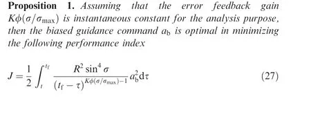
Furthermore,the impact time error will approach 0 as t →tf,i.e.,=0 under the proposed guidance law.
Proof. Denote

Then, according to Theorem 1 in Ref.8, the biased command ab, shown in Eq. (25), is the solution of the following finite-time optimal regulation problem
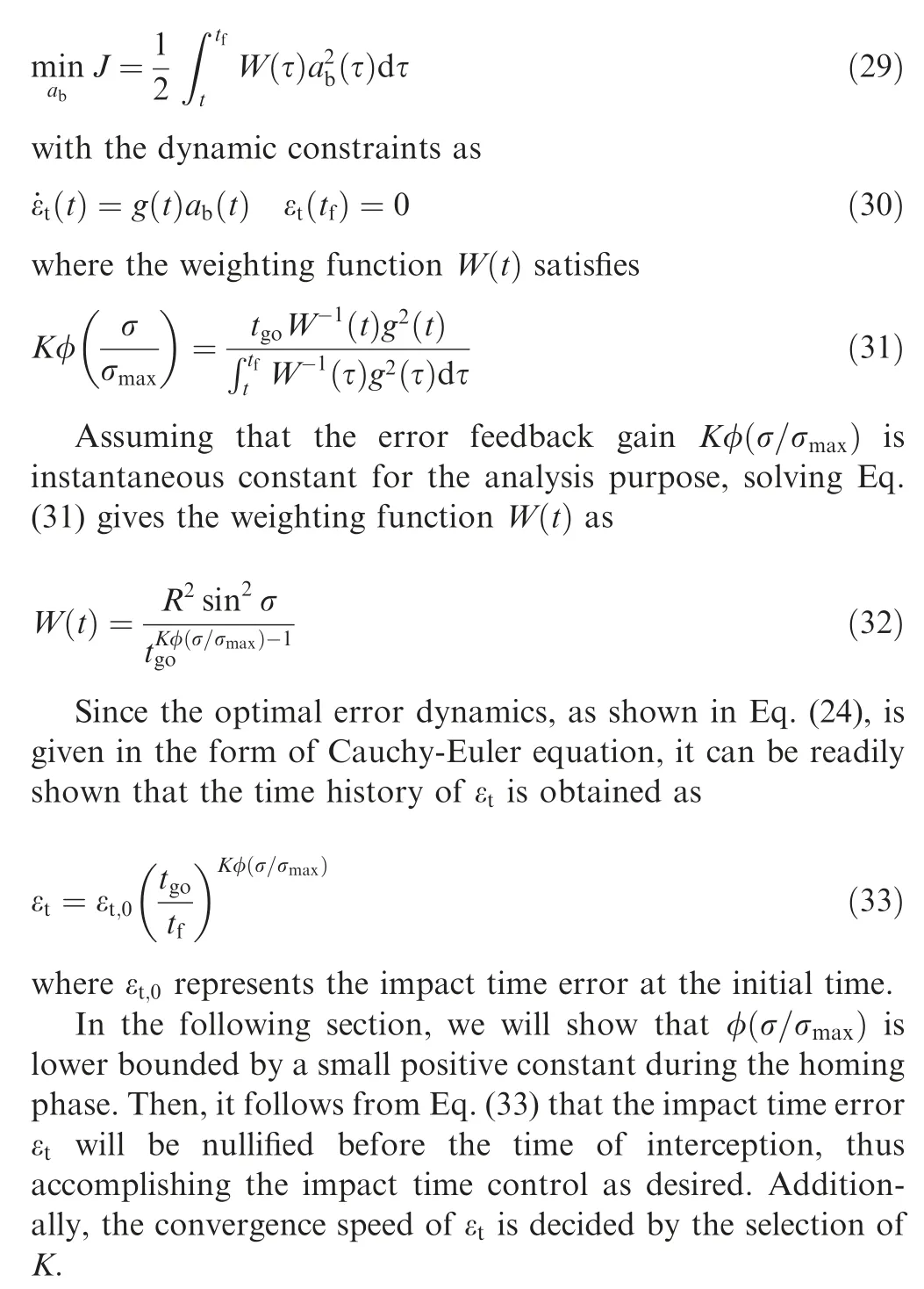
In Proposition 1, the performance index as shown in Eq.(27) can give us general insights into the command pattern of the proposed guidance law and the behavior of guidance laws under the circumstance of impact time control. From Eq. (27), we can readily observe that the magnitude of the weight function decreases as R and σ decrease for a given time-to-go. Therefore, the resultant guidance command might increase as R or σ decrease as shown in Eq.(27).This is a general phenomenon of impact-time-control guidance laws.For a stationary target,the parameter σ can be considered as a heading error.Therefore,decreasing R and σ means that the missile approaches a target, converging to a collision course. For the impact time control, the missile needs to make a detour away from the desired collision triangle, hence adjusting the flight time as desired. By the geometric rule, we readily know that changing the flight trajectory is getting easy as the missile deviates from the collision course.Namely,once the missile makes the collision course to a target, more control effort is required to correct the flight time as desired.This is a general characteristic of impact time control guidance laws, and the above performance index implies this fact. Additionally, based on the above performance index,we can determine the command pattern of the proposed guidance law. A more detailed analysis will be provided in Section 4.3.
It is worth noting that the result of Proposition 1 is based on the approximation of the instantaneous constant for the purpose of theoretical analysis.Therefore,the results obtained might not be exactly the same as the actual ones.However,this assumption is widely-utilized in guidance law analysis Refs.27–29 and we would say that the results obtained are enough to grasp the overall properties of the proposed method.
4.2. Velocity lead angle analysis
In this subsection, we will analyze the properties of velocity lead angle σ under the proposed guidance law to show that condition Eq. (9) is always satisfied. The results are presented in the following proposition.
Proposition 2. If the initial velocity lead angle σ0satisfies|σ0|≤σmax, then the proposed guidance law ensures that|σ|<σmaxfor all t>0.
Proof. In the following, Proposition 2 will be proved in two steps. Step 1 will show |σ|≤σmaxholds for all t>0 if|σ0|≤σmaxand Step 2 will subsequently demonstrate the velocity lead angle σ will never achieve the maximum permissible value σmaxfor all t>0 under the proposed guidance law if|σ0|≤σmax.
Step 1. Differentiating σ with respect to time and substituting Eq. (26) into it yields
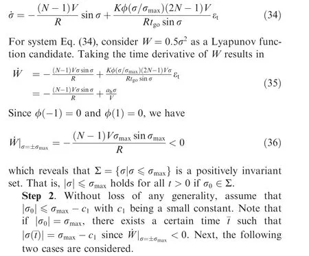
Case 1. abσ<0. Under this condition, it follows from
Eq. (35) that ˙W <0, which means |σ|<σmaxis true.Case 2. abσ ≥0.If ˙W >0,there exists a small constant c2such that ˙W||σ|=σmax-c2=0 since function ˙W is continuous with respect to σ and ˙W|σ=±σmax<0. Therefore, we can readily conclude that the velocity lead angle σ is con-

Fig. 2 Examples of candidate function
Proposition 3. Under the proposed guidance law, the velocity lead angle σ will converge to zero at the time of impact, i.e.,=0.

4.3. Guidance command analysis

Table 1 Initial conditions for homing engagement.
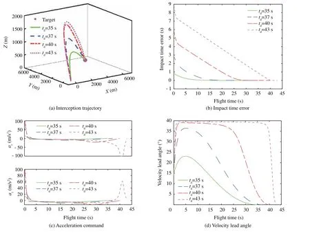
Fig. 3 Simulation results of proposed guidance law with various impact times.
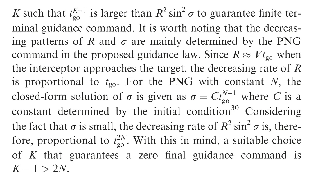
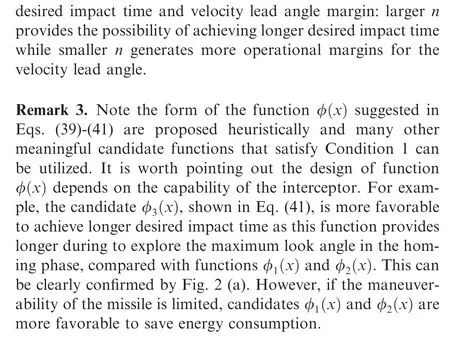
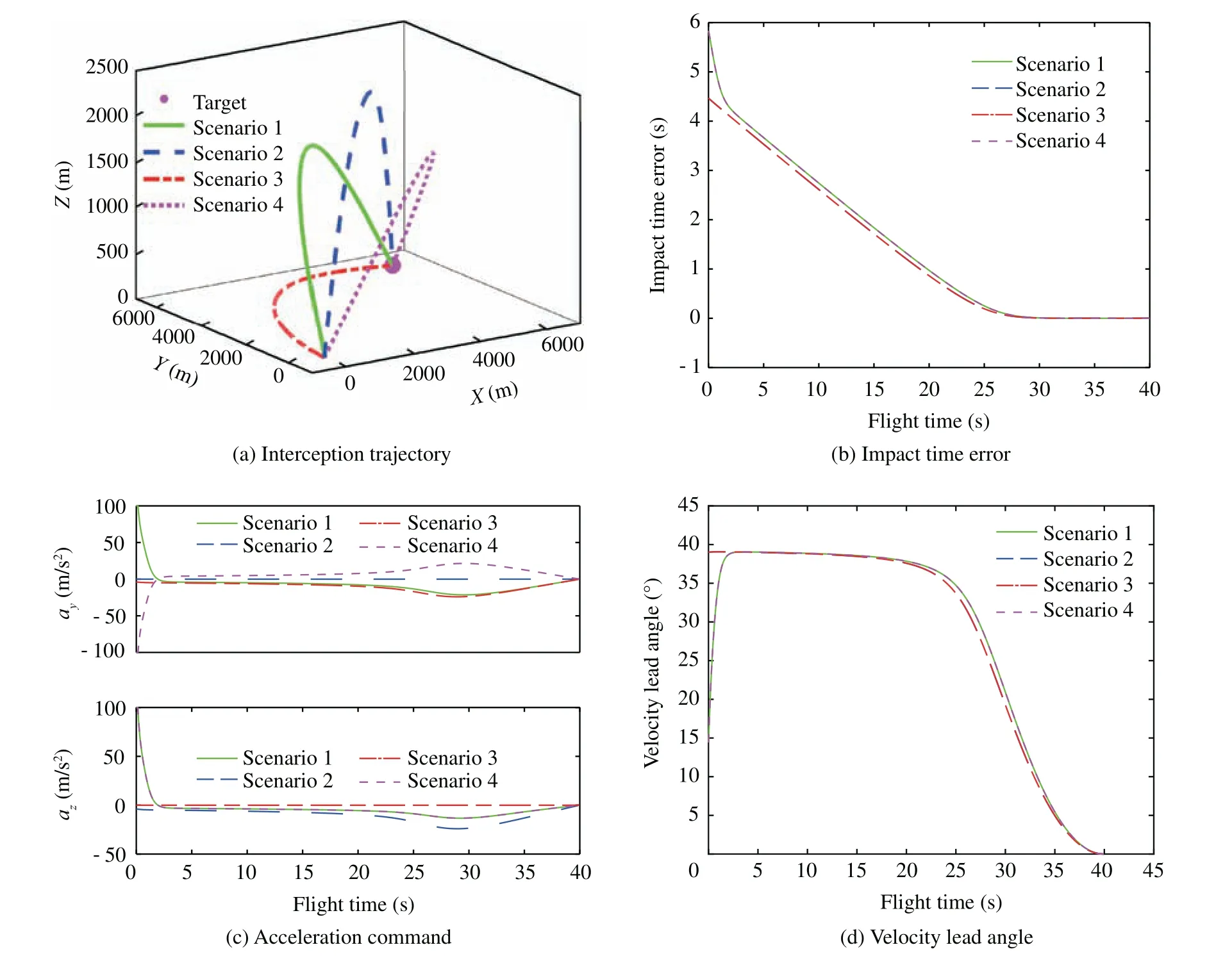
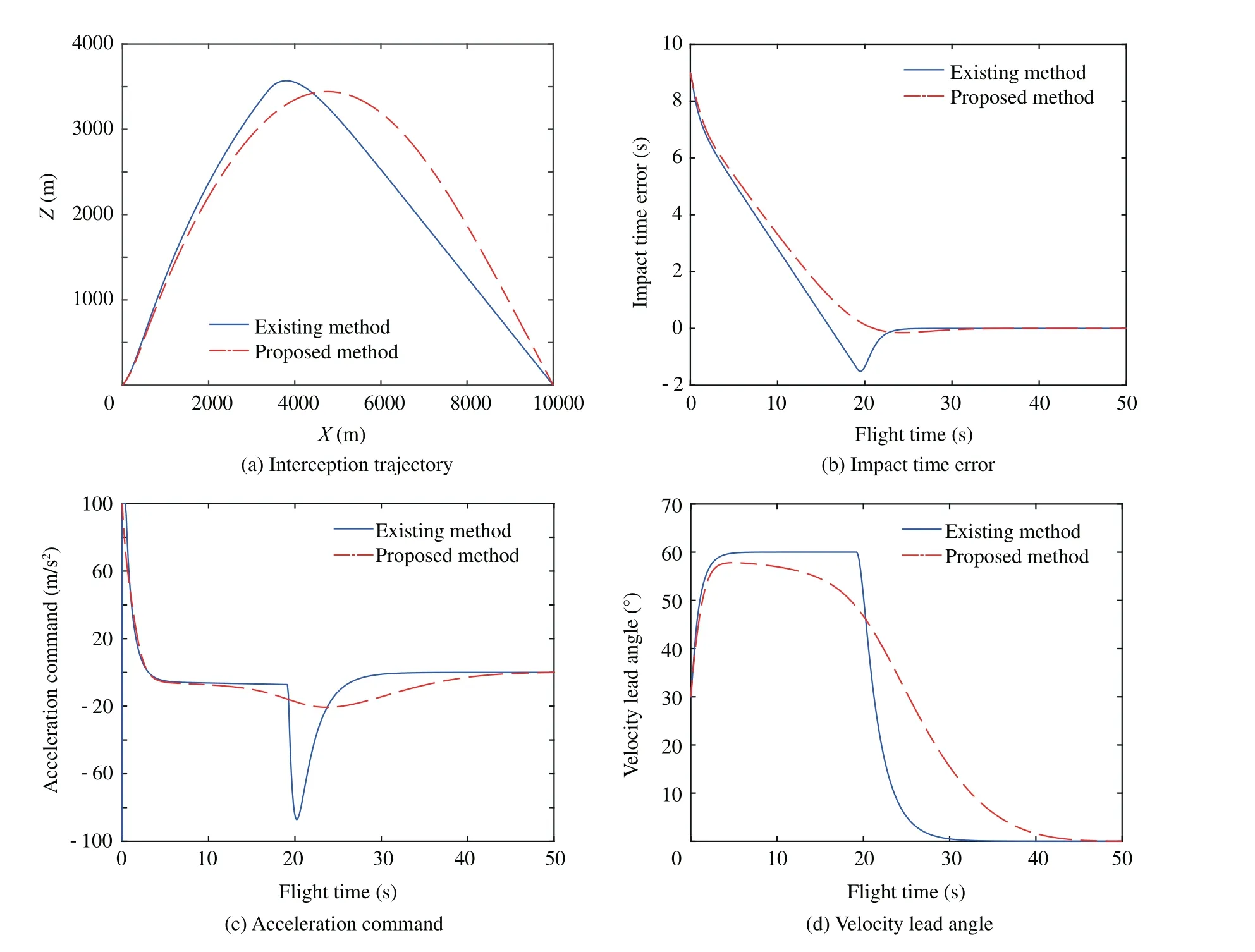
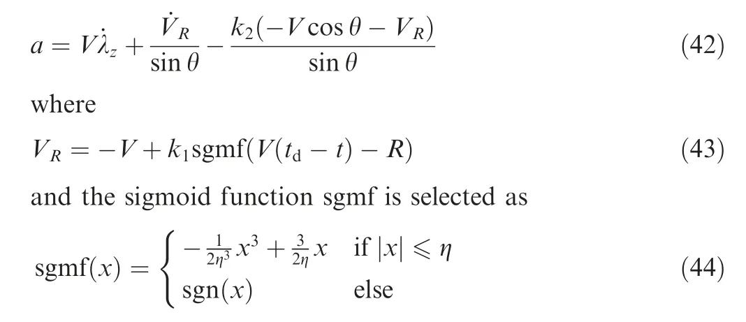
From Eq. (26), it is found that the condition σ=0 is considered as a singularity in terms of generating the guidance command. This condition might result in an abrupt guidance command.But,it can be readily verified that this singular condition is trivial because σ does not become zero (i.e., σ ≠0)except for the final interception point for the stationary target.To see this, assume that there exists a certain time t3,0 Fig. 4 Simulation results of proposed guidance law with various velocity lead angle constraints. Table 2 Summary of initial conditions. Fig. 5 Simulation results of proposed guidance law with various initial conditions. In this section, the proposed guidance law is tested with various impact times td=35,37,40,43 s. Note that td=43 s is the approximated maximum desired impact time for the considered scenario through numerical analysis. The maximum permissible lead angle is set as σmax=40°.Fig.3(a)compares the interception trajectory obtained from different desired impact times, showing that a longer and more curved path is required for a larger impact time.The impact time error under various conditions obtained from the proposed guidance law is depicted in Fig.3(b),demonstrating that the impact time error becomes zero at the final time.The impact time errors recorded in simulations under the considered four different conditions are less than 0.05 s. This result indicates that the proposed method can successfully intercept the target with an accurate impact time as desired. The missile acceleration command is presented in Fig. 3 (c). Clearly, more energy consumption is observed at the beginning of the homing phase as tdincreases.Therefore,the duration of the guidance command saturation is longer with a larger desired impact time. Additionally, the guidance commands converge to zero at the time of interception in all the considered scenarios. From Fig. 3 (c), we can also note that the magnitude of acceleration command increases significantly during the terminal homing phase when the desired impact time approaches its maximum feasible value. It is caused by the fact the available time for driving the velocity lead angle to zero relatively short once the desired impact time approaches its maximum permissible value.Fig.3(d)shows the profile of the velocity lead angle when employing the proposed guidance law. The results in Fig. 3 (d) reveals that the magnitude of the velocity lead angle initially increases intended to reduce the impact time error,and finally converges to zero at the final time to ensure target interception. In this subsection, the performance of the proposed guidance law is evaluated with various velocity lead angle constraints σmax=40°,45°,50°,55°. The desired impact time is set as td=42 s.The simulation results,including interception trajectories, impact time error, missile acceleration commands, and velocity lead angle profiles, are presented in Fig. 4, demonstrating that the missile successfully intercepts the target at the specific time with various lead angle constraints.Fig.4 also reveals that the proposed guidance law tries to leverage the maximum available lead angle to reduce the impact time error during the initial period of the flight.For this reason,the interception trajectory is more curved and more control energy is required during the initial period with a larger σmax.Therefore,the impact time error under the proposed guidance law with a larger FOV constraint converges to zero faster, as shown in Fig. 4 (b). With smaller σmax, however, a slightly sharper turn of the acceleration command can be noted from Fig. 4 (c)when the missile approaches the target.The reason for this fact is that the interceptor with smaller σmaxhas a shorter time in regulating the lead angle to zero. Now,let us examine the performance of the proposed method with various initial conditions, as shown in Table 2.The maximum permissible lead angle is set as σmax=40°and the desired impact time is set as td=40 s. Note that scenario 1 is the same as the scenario studied in previous subsections.Scenarios 2 and 3 are two extreme scenarios in which the initial velocity lead angle approaches its maximum feasible value.The interceptor in scenario 4 has opposite initial flight path angle in the horizontal plane as scenario 1. The interception trajectories of all scenarios are shown in Fig. 5 (a), which reveals that the missile flight trajectory of scenario 2 is located in the vertical plane and the interception trajectory of scenario 3 locates in the horizontal plane. This can be attributed to the fact that the proposed 3D guidance law converges to a 2D impact time control guidance law when the initial flight path angle of one plane becomes zero. This can be easily verified by the guidance command Eq. (26). Fig. 5 (b) compares the impact time errors of all scenarios under the proposed guidance law.It follows from this figure that scenarios 1 and 4 have the same impact time error dynamics since these two scenarios have the same initial velocity lead angle.Similarly,scenarios 2 and 3 also have the same impact time error dynamics. The guidance commands in both pitch and yaw planes for all scenarios are presented in Fig.5(c).Since the proposed guidance law in scenarios 2 and 3 reduces to 2D guidance, the commanded acceleration in one plane becomes zero. We can also note that the scenarios 1 and 4 share the same guidance command in the pitch plane while having the opposite value in the yaw plane. The reason is that these two scenarios have symmetric interception trajectories with respect to a vertical lpane,as confirmed by Fig.5(a).Fig.5(d)shows the time histories of look angle under the proposed guidance law for all scenarios.The result in Fig. 5 (d) reveals that the velocity lead angle can be constrained with its feasible region and converges to zero under the proposed guidance law with various initial conditions. To further show the superiority of the proposed guidance law,comparison simulation is conducted in this subsection. As mentioned before, up to the best of the author’s knowledge,no impact-time-control guidance law with seeker’s FOV constraint in a 3D space is available in the open literature. There have been only some studies on some impact-time-control guidance laws considering the seeker’s FOV limit in a 2D space. Because of this reason, there is a limitation to compare the proposed method to existing methods directly. Therefore,in the comparison study, the proposed method is compared to existing methods, in a vertical engagement plane only. For the purpose of comparison, the impact-time-control guidance considering the seeker’s FOV limits based on the backstepping control technique31is implemented.The guidance command of this method is given as Fig. 6 Comparison results between proposed method and existing method. Table 3 Quantitative comparisons of control effort. In the above guidance command, k1,k2, and η represents the design parameters. For comparison, the engagement scenario and the design parameters given in Ref.31are used:td=50 s,σmax=60°,k1=125,k2=1, and η=200. More detail information can be found in Ref.31. The simulation results obtained from these two different guidance laws are shown in Fig. 6, which clearly indicates that all cases can successfully intercept the target while satisfying the desired impact time.However,the difference between these two guidance laws lies in the fact that the existing method shows an abrupt change of the guidance command, as can be confirmed by Fig. 6 (b). This characteristic is not desirable for the guidance operation because it might result in the instability of guidance loop.32The control energy consumption, defined as ∫tf0 a2dt, is recorded as in Table 3. From this result, it is concluded that the proposed guidance law consumes less control energy,compared with the existing method. This is because the proposed method is developed based on the concept of optimal error dynamics.8Last but not least, the proposed method can be applied to a 3D engagement scenario,unlike previous methods including Ref.31. In this paper, the impact time control guidance problem for a tactical missile with seeker’s FOV constraint against a stationary or a slowly-moving target in a 3D engagement scenario is suggested. The proposed guidance law consists of two command terms: a baseline 3D PNG command term and a feedback command term of an impact time error. Theoretical analysis uncovers that the impact time error will be nullified as the missile approaches the target. The optimality of the biased feedback term and the behavior of the velocity lead angle are also discussed to provide better insights into the proposed guidance law. Although the proposed method is developed for a stationary target or a slowly-moving target, the guidance algorithm developed can also be leveraged for a non-maneuvering target by utilizing the predictedinterception-point concept.4.4. Selection of φ
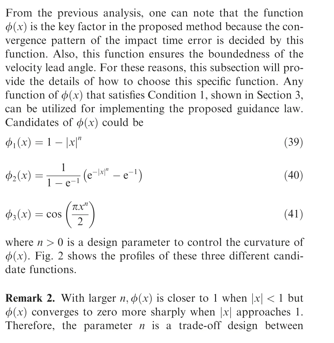
5. Numerical simulations


5.1. Performance with different impact times
5.2. Performance with different velocity lead angle constraints
5.3. Performance with different initial conditions
5.4. Comparison with other guidance laws

6. Conclusions
 CHINESE JOURNAL OF AERONAUTICS2021年2期
- CHINESE JOURNAL OF AERONAUTICS的其它文章
- Recent active thermal management technologies for the development of energy-optimized aerospace vehicles in China
- Electrochemical machining of complex components of aero-engines: Developments, trends, and technological advances
- Recent progress of residual stress measurement methods: A review
- Micromanufacturing technologies of compact heat exchangers for hypersonic precooled airbreathing propulsion: A review
- Towards intelligent design optimization: Progress and challenge of design optimization theories and technologies for plastic forming
- A combined technique of Kalman filter, artificial neural network and fuzzy logic for gas turbines and signal fault isolation
