Electromagnetic scattering characteristics of coaxial helicopter based on dynamic transformation method
Zeyang ZHOU, Jun HUANG, Jinjun WANG
School of Aeronautic Science and Engineering, Beihang University, Beijing 100083, China
KEYWORDS Coaxial helicopter;Dynamic electromagnetic scattering;Radar cross section;Radar stealth;Rotor
Abstract With the development of coaxial rotors and high-speed helicopters, the electromagnetic scattering characteristics of coaxial helicopters have gradually become a research hotspot.In order to deal with the Radar Cross-Section(RCS)of high-speed rotating rotors or coaxial main rotors,a Dynamic Scattering Method (DSM) based on dynamic process simulation and grid coordinate transformation is presented. Instantaneous electromagnetic scattering from rotors and helicopters is solved using Physical Optics (PO) and Physical Theory of Diffraction (PTD). Important factors are analyzed and discussed in detail, including individual rotor rotation, azimuth, elevation angle,fuselage,pitch angle,and roll angle.The results show that the electromagnetic scattering characteristics of rotor-type components are dynamic and periodic. The dynamic RCS period of a single rotor is related to the dynamic RCS period of the coaxial main rotor. Choosing different observation angles and attitude angles has a great impact on the static and dynamic RCS of the helicopter.The presented DSM is effective and efficient to analyze and determine the dynamic electromagnetic scattering characteristics of conventional helicopters or coaxial helicopters.
1. Introduction
In recent years, helicopter technology has been moving towards stealth and high speed.1,2The research on the aerodynamic and electromagnetic scattering characteristics of coaxial helicopters has also received more and more attention.
The aerodynamic and stealth designs of a rotor or helicopter are usually indivisible.For the optimization of the aerodynamic and acoustic characteristics of the rotor, hierarchical Kriging model, the validated Reynolds Averaged Navier-Stokes(RANS)solver and FW–Hpdsequation are comprehensively utilized and developed.3To solve the Radar Cross-Section (RCS) for helicopters and rotors,4high-frequency method is used to calculate the RCS curve of the target under different azimuths and elevation angles.5Genetic Algorithms and Kriging surrogate models are used to optimize the design of the rear fuselage surface of the helicopter,6while changes in the shape of the rear fuselage still need to be discussed for changes in the maneuverability of the fuselage and the stealth characteristics of the side and tail.7Physical Optics (PO) and Equivalent Currents Methods (ECM) were used to calculate and analyze the electromagnetic scattering characteristics of two helicopters.8The aerodynamic characteristics of the coaxial main rotor helicopter in the forward flight and hovering states are simulated by numerical methods in detail.9,10It can be seen that the aerodynamic and static electromagnetic scattering characteristics of the single rotor are still the mainstream of research,the aerodynamics of the coaxial main rotor has gained more and more attention,and the static RCS of the coaxial rotor still needs more work.
However, as a high-speed rotating component on a helicopter,the rotor or coaxial rotor itself has dynamic echo characteristics. A coherent laser detection micro-Doppler echo model of a moving extended rotor is constructed using the physical-optical surface element method.11The stealth design,frequency characteristics and important scattering sources of single rotor and coaxial rotor can be studied by PO.12–14The stealth design of military helicopters can effectively reduce the detection probability of enemy detection equipment to the helicopter,15–17thereby enhancing the survivability of the helicopter. The RCS curves of propeller and non-propeller helicopter models were calculated using PO method, and the concept of RCS gain value for blade impact analysis was proposed.18–20Using the quasi-static method, the Doppler spectrum of the moving target can be obtained from the RCS data of the rotor.21–23Based on the structural characteristics of helicopter blades and radar echo characteristics, a novel rotor scattering enhancement technology is presented,24while new research method is needed to deal with the dynamic scattering of the rotor when the attitude change of the aircraft is considered.25Grid transformation technology is used in global ocean models,26bearing box calculations and low-amplitude structural strata.27,28Changes in the optimized geometry and changes in real-time flight status are all factors that cannot be ignored by the electromagnetic scattering of coaxial rotors.29,30Therefore, it could be a new idea to use the above grid transformation methods,31coordinate axis transformation, and narrow surface element method to simulate the dynamic electromagnetic scattering process of coaxial rotors.32–34
Most research in history has focused on the RCS calculation of single rotor,that is,the static electromagnetic scattering characteristics, or using the quasi-static method to calculate the RCS of the rotor at a small number of sample points,but the dynamic RCS calculation method of the rotor or coaxial rotor is lacking. Aimed at the motion characteristics of the coaxial twin rotors, combined with grid technology and coordinate conversion methods, this paper attempts to establish a dynamic simulation method to calculate and analyze the dynamic RCS of single rotor or multi-rotor, which has practical significance and application value for studying the radar stealth of coaxial helicopters.
In this paper, the dynamic RCS calculation method is presented in Section 2. Coaxial helicopter and rotor models were built in Section 3.The results of rotor electromagnetic scattering are provided and discussed in detail in Section 4. Finally,the full text is summarized in Section 5.
2. Dynamic scattering method
The dynamic electromagnetic scattering schematic of the coaxial helicopter is shown in Fig. 1, where c is the propagation speed of electromagnetic waves,t is time,subscript 0 represents initial time, D is the distance between the helicopter and the radar station, α is the azimuth between the radar station and the helicopter, β is the elevation angle between the radar station and the helicopter, Vtip,m1is the tip speed of main rotor 1,Vtip,m2is the tip speed of main rotor 2,Ar,m1is the rotation angle of main rotor 1, Ab,m1is the angle between adjacent blades of main rotor 1,and Ab,m2is the angle between adjacent blades of main rotor 2.
2.1. Instantaneous scattering calculation
For a rotor that is stationary or in a transient state, its RCS can be determined by PO. At this time, the magnetic vector position of the radar wave inducing the induced current in the illuminated area of the rotor surface could be described as

where A(r) is the magnetic vector position generated by the surface induced current, μ is the permeability coefficient, Jsis the induced current on the target surface, r′is the coordinate vector of the source point,S is the target surface,k is the wave number in free space, and R is the distance between the field point and the source point:
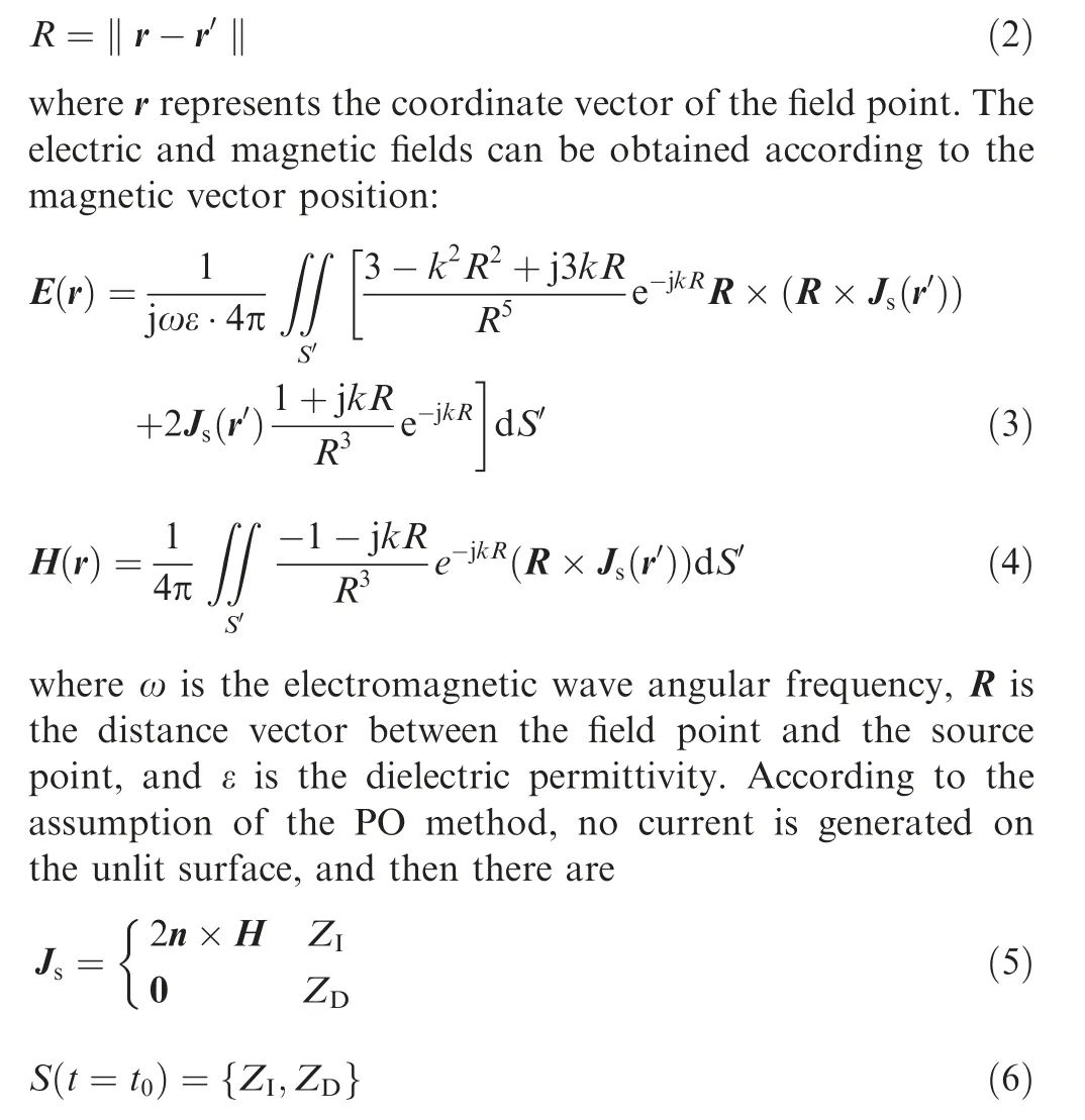
where t0represents the initial time or any other instant,n is the unit normal vector of the outer normal direction of r’ at the surface of the scatterer, ZIis the illuminated area, and ZDis the dark area. The electric field formula can be converted to the following form:
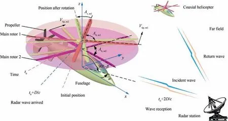
Fig. 1 Schematic of dynamic electromagnetic scattering for coaxial rotor helicopter.
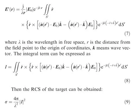
However, the rotor also has many edges and smaller areas,the Physical Theory of Diffraction (PTD) is used to solve the edge diffraction of the target surface. At this time, the actual scattering field is the sum of PO contribution and edge contribution:

where JSrepresents the total current in the actual scattering field, JPOrepresents the induced current determined by PO method, JPTDrepresents the current determined by PTD.Diffraction coefficients obtained by PTD do not appear odd at reflection boundaries, and for more description of PO+PTD, please refer to Refs. 2,5.
2.2. Dynamic process simulation
Static or instantaneous calculations are not enough for highspeed rotating rotors, and thus the Quasi-Static Principle(QSP) is often used to handle this dynamic process:
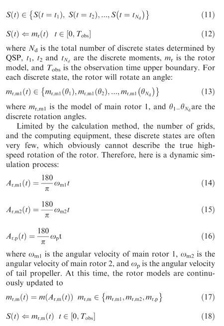
where mr,mis the rotor model. Because the rotation of the rotor is obviously periodic, the observation time range of its dynamic RCS should have a minimum range.
The speed of the main rotor and the thrust propeller are different,and the number of blades is also different,which results in their periodic inconsistencies, and thus a basic passage time is defined as
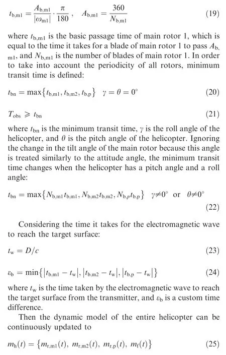
where mh(t)is the dynamic model of the helicopter,and mf(t)is the model of the helicopter fuselage with the main rotors and thrust propeller removed.
2.3. Grid coordinate transformation
Converting the dynamic model of the helicopter to the grid data required for electromagnetic calculation, we have
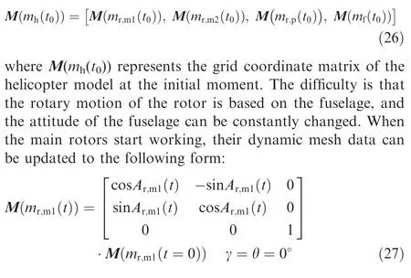
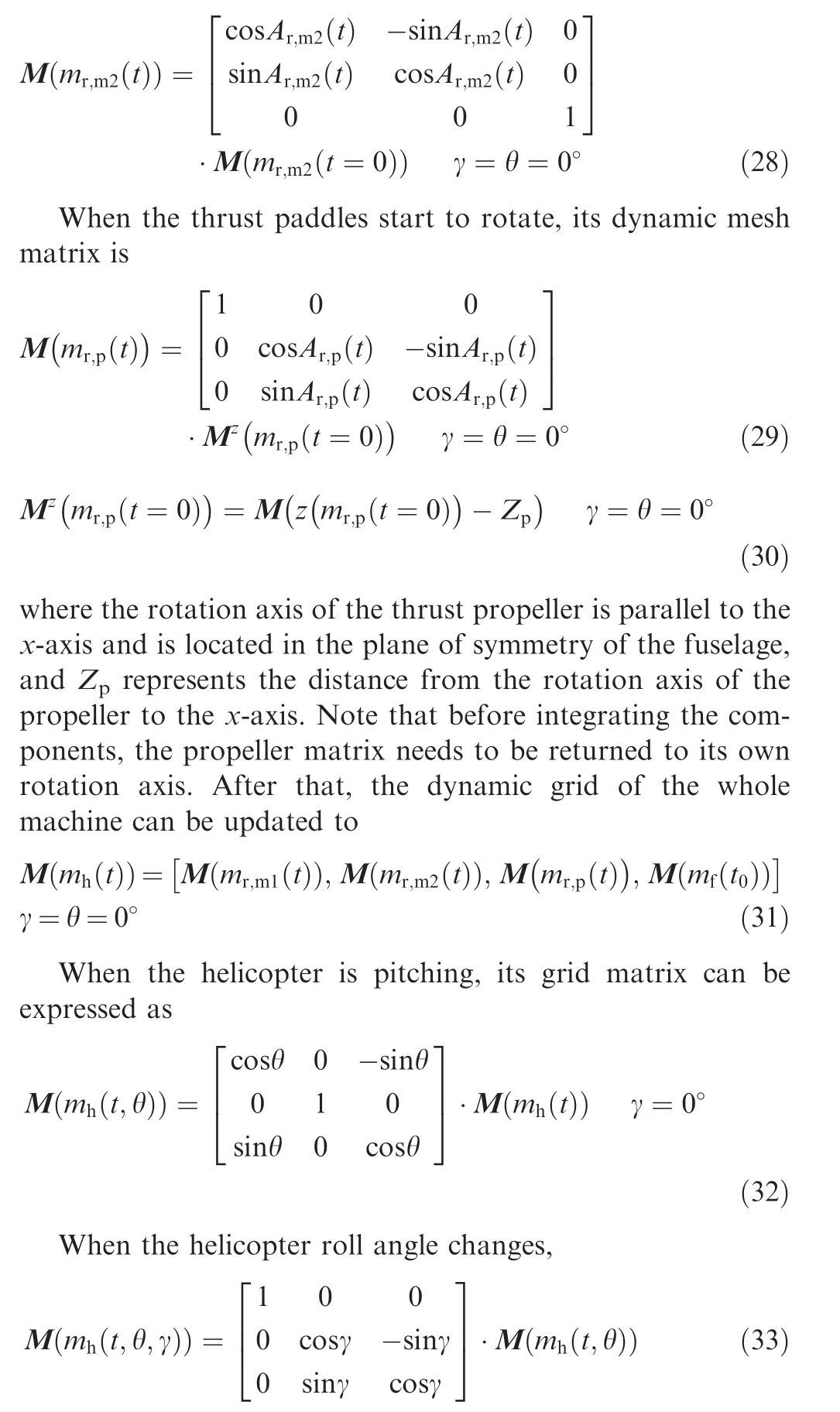
The above Dynamic Scattering Method is verified by PO+MOM (Method Of Moment)/MLFMM (Multi-Level Fast Multipole Method)in FEldberechnung bei Korpern mit beliebiger Oberflache (FEKO) as shown in Fig. 2, where the radar wave uses horizontal polarization, fRis the frequency of the radar wave, and the balde tip Mach number of the propeller is 0.527.Due to the limitation of FEKO’s dynamic simulation,QSP is used to discrete the rotation state of the rotor to obtain a denser rotation angle and then calculate this dynamic process within a given time range. The results show that the dynamic RCS curve obtained by DSM can be in good agreement with the calculation results of FEKO, while the former can reflect the continuity on the time scale well,and the observation duration and observation accuracy can be defined by DSM. This implies that using DSM to calculate the dynamic electromagnetic scattering characteristics of the rotor is accurate and efficient.
The above results also show that the RCS of the rotating rotor does have dynamic characteristics, with a maximum difference of 28.308 dBm2, and thus more research work is still needed for the main rotors and the entire helicopter in the following content.
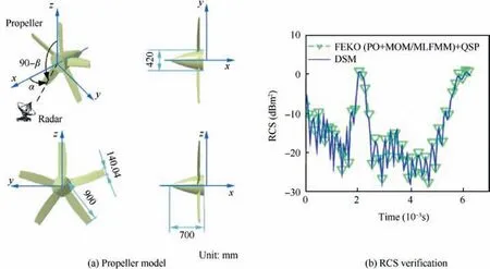
Fig. 2 Verification of rotor dynamic RCS on mr,p at α=210°, β=γ=θ=0°, fR=6 GHz.
3. Helicopter and rotor model
Referring to the design of the Sikorsky X-2 high-speed helicopter,22the coaxial helicopter established in this paper is shown in Fig. 3, where Lhis the length of the helicopter, Hhis the height of the helicopter, Wfis the width of the fuselage,Rm1is the radius of the main rotor 1, Rm2is the radius of the main rotor 2, and Rpis the radius of the propeller.
The main dimensions of the helicopter are shown in Table 1,where Zm1is the distance from the plane of main rotor 1 to the coordinate origin, Zm2is the distance from the plane of main rotor 2 to the coordinate origin, Xpis the distance from the plane of propeller to the coordinate origin, Xhtis the distance from the trailing edge of horizontal tail to the yz plane,and Zvtis the distance from the bottom end face of vertical tail to xy plane.
The geometry layout of the main rotor and thrust propeller are shown in Table 2,where Attis the twist angle of blade tip,Atris the twist angle of blade root,ωris the angular velocity of the rotor, and Rhubis the outer radius of rotor hub. The rotational speeds of the two main rotors are equal and their directions are opposite.
The surface of the model of the helicopter and each rotor part is divided into a high-quality and precise triangular surface element mesh through the high-precision unstructured mesh technology as shown in Fig.4.Mesh encryption technology is used in small areas, including the leading and trailing edges of the rotors, the edges of the horizontal and vertical tails as well as the local lines of the fuselage.
4. Results and discussion
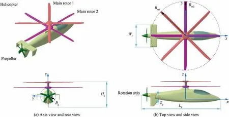
Fig. 3 Establishment of coaxial main rotor helicopter model.

Table 1 Main dimensions of various parts of helicopter.

Table 2 Geometrical characteristics and motion parameters of rotors.
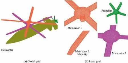
Fig. 4 Surface mesh for helicopter and rotor parts.

Fig. 5 Dynamic electromagnetic scattering characteristics of coaxial main rotor surface at α=0°, β=0°, γ=θ=0°, fR=6 GHz.
Fig. 5 presents that the rotation of the rotor does cause changes in the electromagnetic scattering characteristics of the surfaces of itself and the coaxial rotor. When t=0.0057 s, the strong scattering source part of the main rotor 1 includes the front surface of the hub, the rear part of the upper surface of the blade 1 and the leading edge of the blade 3, while for the main rotor 2, the leading edge of the blade 4, the rear of the upper surface of the blade 2 and the front of the hub appear dark red. These characteristics are derived from the mediocre design of these curved surfaces,which makes them unable to deflect radar waves well to nonthreatening positions. When t=0.0177 s, the original red(about -10 dBm2) on the surface of the blade 2 of the main rotor 1 faded away, and only a small amount of yellow and orange(-22 to-18 dBm2)appeared at the leading edge,while blade 4 turns 53.1°, and the dark blue on its surface turns orange-yellow. For the main rotor 2, a large area of orange yellow(about-20 dBm2)on the surface of paddle 1 gradually deepens into red (near -5 dBm2) because the angle between the entire blade surface and the radar wave gradually increases, and the favorable incident angle of the deflected radar wave is lost. These results show that DSM can well describe the dynamic electromagnetic scattering characteristics of individual rotor and coaxial rotors.
4.1. Effects of individual rotor
Fig. 6 provides that the continuous rotating motion of the rotor makes its electromagnetic scattering characteristics show a clear periodicity, and when the attitude angles of the rotor plane are 0°, this period is equal to its basic passing time.For Fig.6(a)here,the rotor’s dynamic RCS curve shows 4 distinct repetitive processes,with a peak size of 31.64 dBm2and a minimum value of -9.539 dBm2, because the radar wave passes through the rotor plane at this time and the blade will enter the next identical rotational movement when it passes through the angle between adjacent blades, and thus period at this time is exactly equal to the basic passing time. For Fig. 6(b), it can be seen that the rotor dynamic RCS period and the basic passing time are both equal to 0.03 s, while RCS characteristics of rotors at different azimuths are significantly different, including peaks and RCS shapes. For Fig. 6(c),σdis the normalized rotor RCS,which is equal to the ratio of the current RCS to the maximum RCS difference, and σdhas no unit. The RCS values here are derived from DSM real-time calculations, not QSP sampling results. The characteristics of these results are consistent with those of Refs.11,23. For Fig. 6(d), fdis the sum of the micro-Doppler frequencies of all surface elements of the rotor at the instant. It can be seen that the total micro Doppler frequency of the rotor appears as a sinusoidal curve, which is consistent with the curve characteristics in Refs. 11,23 This shows that DSM can well capture the dynamic and periodic characteristics of rotor RCS.
Table 3 shows that the average RCS value of the main rotor 1 in 0–0.03 s is higher than that of the main rotor 2 by more than 15.78 dBm2. When α=30°, the difference between the average RCS of two separate main rotors even reached 26 dBm2. The reason for these changes is that the main rotor 1 has one more cylindrical shaft fairing than the main rotor 2, and the cylindrical design is not easy to deflect the incident radar waves in the circumferential direction, thus improving the overall RCS level of the main rotor 1. It can be seen that the design of the coaxial main rotor shaft fairing is still related to its overall radar stealth characteristics.
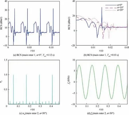
Fig. 6 Dynamic RCS and time–frequency characteristics of rotor at β=0°, γ=θ=0°, fR=6 GHz.
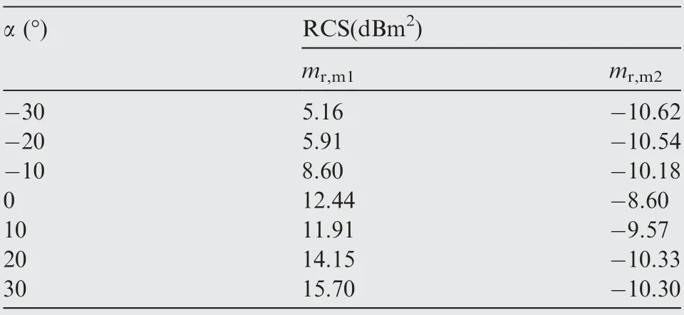
Table 3 Dynamic RCS mean of main rotor at β=0°, t=0–0.03 s, γ=θ=0°, fR=6 GHz.
Fig. 7 indicates that the RCSs of the main rotor 2 and the thrust propeller also show strong dynamic characteristics under different azimuth angles. For Fig. 7(a), the RCS-time curve at α=30° and 40° both have two large peaks, while the RCS-time curve at α=50° has only one, with a size of 12.07 dBm2appearing at t=0.0134 s. Since the main rotor 2 and the main rotor 1 have the same number of blades, blade design, and rotation speed, their dynamic periods at this time are equal, which is equal to the basic passing time of 0.03 s.For Fig.7(b),the three RCS time curves are generally similar,but there are differences in peak size and local fluctuations.The maximum value of the RCS time curve at α=180° is 13.07 dBm2, that of the RCS time curve at α=190° is 13.9 dBm2, and that of the RCS time curve at α=200° is 3.162 dBm2.During a basic passage time interval,as the rotor rotates, the angle between the surface and the radar wave will continuously change, so that the strong scattering sources on its surface are constantly transferred, and the scattering characteristics of the leading and trailing edges are constantly changing. These cause the electromagnetic scattering of the entire rotor to show dynamic characteristics.
In general,the respective electromagnetic scattering characteristics of main rotor 1, main rotor 2 and thrust propellers show obvious dynamic characteristics when rotating. When the attitude angles are all equal to 0°, the respective dynamic periods are equal to their basic passing time.
4.2. Effects of observation angles
Fig.8 reveals that the RCS of the coaxial main rotor at different azimuth angles shows different dynamic characteristics.For Fig. 8(a), the overall level of the dynamic RCS curve of main rotor 1 is significantly higher than the dynamic RCS curve of main rotor 2,where the former has a maximum value of 20.24 dBm2, while the latter has a maximum value of only 3.788 dBm2, and the reason for these changes is that the main rotor 1 has a 0.399 m round tube fairing under the hub,which will continue to form more strong scattering sources,although its outer diameter is smaller than the outer diameter of the main rotor 2 by 0.03 m.For Fig.8(b)and(c),it can be clearly found that the period of the RCS time curve of the coaxial main rotor at α=30°and 40°is 0.12 s, which is exactly equal to 4 times the dynamic period of the main rotor 1 or 2 alone.This is because the main rotors 1 and 2 are set to rotate in the opposite direction. When one of the blades (recorded as B1-1)of the main rotor 1 meets a blade of the other main rotor for the first time at the projection direction in the xy plane, the angle of rotation is smaller than Ab,m1. As B1-1 continues to rotate until it encounters all the blades of the main rotor 2,it begins the cyclical ‘‘meeting rotation”. For Fig. 8(d), the peak sizes of the RCS curves at different azimuth angles are similar (around 20.26 dBm2), but the peak positions are slightly different.The shapes of the three RCS curves are similar,while the minimum and local fluctuations are obvious dissimilarity.Table 4 presents that the average RCS of the coaxial main rotor fluctuates slightly within the azimuth range of 30°to 80°, and the RCS mean is basically stable at 11.96–12.04 dBm2. At this time, the radar wave passes through the coaxial main rotor disk.Both the hub and the shaft are strong scattering sources, which can cover most of the dynamic electromagnetic scattering changes caused by blade rotation.These results indicate that the RCS level of the coaxial main rotor is significantly higher than that of the main rotor alone.In the case of no attitude angle, the dynamic period of the coaxial main rotor is four times that of the main rotor alone.When we observe at different azimuth angles, the dynamic RCS curve of the coaxial main rotor is obviously different,and the influence of azimuth angle cannot be ignored.

Fig. 7 Dynamic RCS of rotor at β=0°, γ=θ=0°, fR=6 GHz.
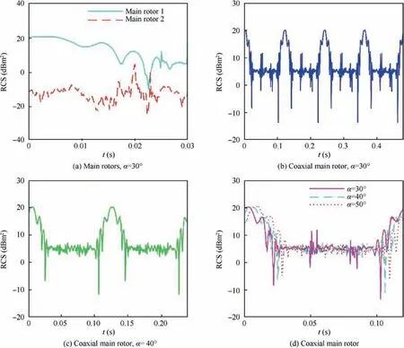
Fig. 8 Effect of azimuth on dynamic RCS of rotor at β=0°, γ=θ=0°, fR=6 GHz.

Table 4 Dynamic RCS mean of coaxial main rotor at β=0°, t=0–0.12 s, γ=θ=0°, fR=6 GHz.
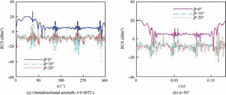
Fig. 9 Effect of elevation angle on dynamic RCS of coaxial main rotor at γ=θ=0°, fR=6 GHz.
Fig. 9 manifests that the elevation angle has a significant effect on the RCS-azimuth and RCS-time curves of the coaxial main rotor. For Fig. 9(a), the RCS-time curve at β=0°mostly fluctuated around 5.682 dBm2, and most of the RCS values at the RCS curve at β =10°and 20°decreased rapidly to about -7.121 dBm2. For an instantaneous or stationary coaxial main rotor, the increase of the elevation angle can effectively avoid the strong scattering source appearing on the hub’s large curvature edge surface and the circular tubular shaft fairing,while the angle between the end face of the blade tip and the radar wave is also improved,which will reduce the RCS level of the coaxial main rotor after increasing the angle of increase. For Fig. 9(b), the maximum value of the RCS curve at β=0° exceeds 20 dBm2, that of the RCS curve at β=10° is 14.81 dBm2appearing at 0.1077 s, while that of the RCS curve at β=20° is 5.562 dBm2appearing at 0.1101 s. Other differences among the three RCS curves include the shape of the curve, the overall level of the RCS,and local fluctuations. The reason for these changes is mainly because the increase of the elevation angle effectively changes the angle between the radar wave and the rotor blade plane,and improves the incident angle of the radar wave to the hub and the shaft. Table 5 provides that the average RCS of the coaxial main rotor shows a trend of increasing first and then decreasing when the elevation angle increases from-20° to 20°. While the elevation angle is increased, the included angle between the radar wave and the rotor shaft can be quickly reduced. This greatly improves the ability of the shaft fairing to deflect radar waves, so the RCS level of the entire rotor is reduced. These results indicate that the change in elevation angle will greatly change the static and dynamic characteristics of RCS within the given range.
In general,the RCS level of the coaxial main rotor is significantly higher than that of the single main rotor.The period of the former is equal to the number of single main rotor blades times the basic passage time of the single main rotor.Choosing the appropriate azimuth and elevation angle can obviously improve the observation results.
4.3. Effects of fuselage
Fig. 10 shows that the presence of the fuselage will greatly increase the RCS level of the helicopter, but it still cannot cover up the dynamic changes brought about by the coaxial main rotor,although the thrust paddle has not started to work.For Fig. 10(a), the overall RCS level of the two RCS-azimuth curves is significantly higher than the RCS of the coaxial main rotor alone. At t=0.0042 s, the RCS azimuth curve shows a peak of 36.03 dBm2at the lateral 92°, and a peak of 35.86 dBm2at α=268°. The other RCS curve has the same peak, but it varies greatly within the different azimuth ranges,including 1.5°–66.4° and 96°–155.8°. This fuselage adopts a certain stealth design in the direction of the head, including a sharper nose, a more inclined cockpit, and a smaller projection area in the head direction. These have caused that the rotation of the coaxial main rotor will have a larger RCS impact on the helicopter in the head direction range. For Fig. 10(b), there are 4 large peaks in the RCS-time curve at α=30°, which are 31.79 dBm2at t=0.025 s, 73.94 dBm2at 0.055 s, 87.36 dBm2at 0.085 s, and 76.44 dBm2at 0.115 s,where the time interval between 2 adjacent peaks is exactly equal to the basic transit time of the single main rotor. The RCS curve at α=90° shows four peaks exceeding 35 dBm2,which are 76.38 dBm2at 0.015 s, 36.06 dBm2at 0.045 s,73.98 dBm2at 0.075 s, and 87.39 dBm2at 0.105 s. The sides of this helicopter’s fuselage are covered with relatively vertical curved surfaces, which allows the side of the fuselage to directly reflect the radar wave that is incident vertically,so that the overall level of the RCS curve at α=90° is significantly higher than that of the RCS curve at α=30°. These results show that DSM can well handle the dynamic electromagnetic scattering problems of fuselage plus coaxial rotor.
Fig. 11 shows that the effect of the fuselage on the electromagnetic scattering characteristics of the helicopter is also significant when we consider that both the coaxial main rotor and the thrust propeller are rotating.For Fig.11(a),the RCS curve at t=0.039 s shows 3 large peaks, which are 76.38 dBm2at α=162°, 87.31 dBm2at α=252°, and 80.21 dBm2at α=342.3°, while the RCS curve at t=0.059 s also shows 3 large peaks, which are 80.22 dBm2at α=42.25°, 76.4 dBm2at α=222°, and 87.33 dBm2at α=312°. The dynamic changes of these peaks are mainly caused by the rotation of the coaxial main rotor with some contributions from the thrust paddles,which is also a dynamic scattering effect that the fuselage cannot block. In the range of head direction α=-15.7°to 40.25°, the difference between the two RCS curves is very small, which is because the fuselage head has a better stealth effect and the fuselage has a better cover to the thrust propeller. However, these two RCS curves are very different in the range of tail and tail-lateral azimuths, including 100.3° to 160° and 161.5° to 239.3°, because the high-speed rotating thrust paddles at this time can directly scatter the incident radar waves to most of the tail and tail-side azimuth directions without being blocked by the fuselage.For Fig.11(b),most of the RCS values of the curve at α=270° are maintained at 28.54 dBm2, the maximum value is 42.05 dBm2, and the minimum value is 25.33 dBm2, while the RCS value of the other curve mostly fluctuates around 15.43 dBm2, with a maximum difference of 16.18 dBm2. The presence of the fuselage also greatly improves the dynamic RCS level of the helicopter at α=270°compared to that at α=180°.These results indicate that the fuselage will block partial dynamic scattering effect of the thrust propeller in the head direction, but it cannot cover the static and dynamic effects of the rotor on the helicopter.
In general, the impact of the fuselage on the static and dynamic RCS of the helicopter is very significant, but it still cannot cover the dynamic effects of the coaxial main rotor and thrust propeller.
4.4. Effects of attitude angles
Fig. 12 presents that the pitching angle and rolling angle have a great influence on the electromagnetic scattering characteristics of the helicopter at the given observation time and angles.For Fig. 12(a), the overall level of the RCS curve is higher at θ=0° (most RCS exceeds 6.256 dBm2), with peaks of 37 dBm2at α=92° and 35.84 dBm2at α=268°, while the overall RCS curve at θ=10° and 20° is low, but the shape is similar. When the pitch angle increases in a positive direction, the nose of the helicopter is continuously raised, which is helpful to improve the strong scattering source of the nose,the hub and the main rotor shaft fairing in the head direction,and also weaken the electromagnetic scattering characteristics in the tail direction of the thrust propeller. For Fig. 12(b), the overall levels of the three RCS curves are similar,but there are differences in peak and local fluctuations. The RCS curve atγ=0° shows three peaks exceeding 37 dBm2, which are 37.16 dBm2at α=62.5°, 48.54 dBm2at α=314.3°, and 38.17 dBm2at α=324.5°. In the positive side direction α=90°±2°, the maximum value of the RCS curve of γ=0° is 35.99 dBm2, while the maximum value of the RCS curve of γ=10° is 23.85 dBm2, and the maximum value of the RCS curve of γ=20° is 20.34 dBm2. It can be found that on the negative side, the peak value also decreases as the roll angle increases. The main reason for these changes is that the increase of the roll angle can prevent the large area of the fuselage’s side plate from being 90° or near vertical to the side radar wave, while the incident angle of the hub and the spinner of main rotor shaft is reduced. These results show that DSM can well describe the effect of attitude angles on the dynamic electromagnetic scattering characteristics of the coaxial helicopter.

Table 5 Dynamic RCS mean of coaxial main rotor at α=30°, t=0–0.12 s, γ=θ=0°, fR=6 GHz.
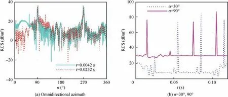
Fig. 10 Effect of fuselage on dynamic RCS of helicopter at Ar,p=0°, γ=θ=0°, fR=6 GHz.
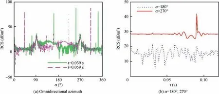
Fig. 11 Effect of fuselage on dynamic RCS of helicopter at γ=θ=0°, fR=6 GHz.
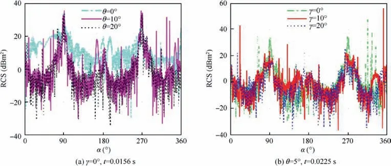
Fig. 12 Effect of attitude angles on dynamic RCS of helicopter at α=0°–360°, β=0°, fR=6 GHz.
Table 6 shows that the instantaneous RCS average of the entire helicopter changes greatly when the pitch angle increasesfrom -30° to 30°. When β increases positively from 0°, the nose of the helicopter is continuously raised. At this time,the average RCS value decreases from 18.21 dBm2to 16.17 dBm2and then rapidly increases to 25.95 dBm2. While β increases negatively from 0°, the average RCS of the helicopter keeps decreasing.Since the helicopter’s lateral RCS distribution occupies a larger part of the entire RCS,changing the pitch angle also continuously changes the electromagnetic scattering characteristics of the fuselage surface.Then consider the changes of the main rotor and tail rotor inclination angle,and the overall RCS of the helicopter has such complicated features.

Table 6 Dynamic RCS mean of helicopter at α=0°–360°, β=0°, t=0.0156 s, γ=0°, fR=6 GHz.
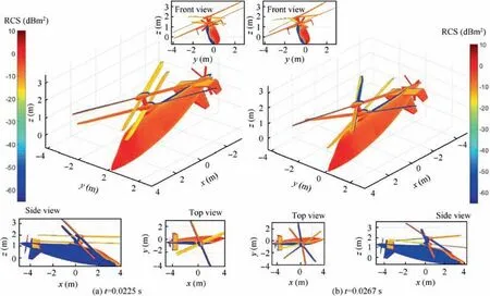
Fig. 13 Effect of attitude angles on surface scattering of helicopter at α=20°, β=0°, θ=-10°, γ=20°, fR=6 GHz.
Fig. 13 indicates that the attitude angles also have a significant effect on the electromagnetic scattering characteristics of the helicopter surface when both the coaxial rotor and thrust propeller are working. For Fig. 13(a), crimson and red (0–10 dBm2) are widely distributed on the surface of the helicopter, including most of the illuminated area of the fuselage,the protruding fairing on the back of the fuselage, the shaft cover of the main rotor, the coaxial main rotor hub, the few blade edges of the main rotor, vertical tail, part of the blade surface of the thrust paddle,the leading edge of the horizontal tail and its winglets,because the bins in these areas are almost perpendicular to the incident radar wave, or the angle of the crocodile radar wave is large, and thus they have a very weak ability to deflect the radar wave.For Fig.13(b),time advances to 0.0267 s, while the main rotor 1, the main rotor 2 and the propeller are rotated by 80.1°,-80.1°and 304.38°respectively compared with the initial position. The electromagnetic characteristics of the fuselage, the top of the fuselage, the main rotor spinner fairing, the main rotor hub and the tail are almost unchanged, while the blade surfaces of main rotor 1 and main rotor 2 have changed a lot,including the appearance of orange-yellow (-20 to -12 dBm2), the deepening of orange-yellow (near -10 dBm2), and the transfer of orange-red(-10–0 dBm2) areas. The overall changes in the electromagnetic scattering characteristics of thrust propellers are small,mainly due to insignificant shifts in red shades. These results indicate that the presence of pitch and roll angles will have a significant impact on the surface electromagnetic scattering characteristics,static RCS and dynamic RCS of the helicopter.
Generally speaking,properly increasing the pitch angle can improve the stealth characteristics of the helicopter, while properly increasing the roll angle is helpful to weaken the lateral electromagnetic scattering characteristics, but these changes cannot cover the dynamic effects of the rotor-like components.
5. Conclusions
By studying the dynamic electromagnetic scattering characteristics of rotors, coaxial rotor, and coaxial main rotor helicopter, the following conclusions can be drawn:
(1) The electromagnetic scattering characteristics of rotortype components including main rotors, coaxial main rotors, tail rotors, and thrust rotors are dynamic. This discovery makes up for the shortcomings determined by the quasi-static principle.
(2) When the pitch and roll angles(and the tilt angles of the paddle) are equal to 0°, the dynamic RCS period of the single rotor is equal to its basic passing time, while the attitude angles of the paddle exist, the dynamic RCS period of the coaxial main rotor is equal to that of the single main rotor times the number of individual main rotor blades.
(3) Choosing a proper azimuth and elevation angle is helpful to improve the RCS of the helicopter, the fuselage will greatly increase the dynamic and static RCS levels of the helicopter, adjusting the pitch angle can improve the dynamic RCS of the helicopter, while the roll angle mainly affects the helicopter’s lateral RCS.
Acknowledgements
This research was supported by the project funded by China Postdoctoral Science Foundation, the Excellence Foundation of Beihang University for PhD, and the National Natural Science Foundation of China (No. 91641123).
 CHINESE JOURNAL OF AERONAUTICS2021年2期
- CHINESE JOURNAL OF AERONAUTICS的其它文章
- Recent active thermal management technologies for the development of energy-optimized aerospace vehicles in China
- Electrochemical machining of complex components of aero-engines: Developments, trends, and technological advances
- Recent progress of residual stress measurement methods: A review
- Micromanufacturing technologies of compact heat exchangers for hypersonic precooled airbreathing propulsion: A review
- Towards intelligent design optimization: Progress and challenge of design optimization theories and technologies for plastic forming
- A combined technique of Kalman filter, artificial neural network and fuzzy logic for gas turbines and signal fault isolation
