Tensile properties of a composite–metal single-lap hybrid bonded/bolted joint
Xioqi LI, Xioqun CHENG,*, Yuji CHENG, Zhiyong WANG,Wenjun HUANG
a School of Aeronautic Science and Engineering, Beihang University, Beijing 100191, China
b Istar-space Technology Co., Ltd., Tianjin 300304, China
c AVIC China Helicopter Research and Development Institute, Jingdezhen 333001, China
KEYWORDS Experimental tests;Failure mechanism;Finite element model;Hybrid (bonded/bolted)joint;Tensile properties
Abstract Hybrid bonded/bolted(HBB)joint has been widely used in engineering practice because it can overcome the potential weakness of pure bonded and pure bolted joints.However,studies on HBB joint are still at the initial stage. In this paper,tensile properties of a composite–metal singlelap HBB joint was investigated experimentally. And a detailed finite element model (FEM) was established to simulate the tensile behavior of the joint.The model was verified by the experimental results. Then the damage propagation and load transfer mechanism were explored based on the FEM. The results show that the HBB joint can provide multi-load transmission paths and resist damage propagation in the adhesive. The HBB joint has higher strength and energy absorption capacity than the pure bonded joint.And the HBB joint has greater initial damage load and tensile stiffness than pure bolted joint. Adhesive fillets can obviously improve the tensile performances of the HBB joint.Lateral stiffness of the joint boundary and testing machine show obvious effects on tensile performances of single-lap hybrid joints.
1. Introduction
In recent decades, increasing application of composite materials in engineering promotes researchers to study the connection techniques between composite and metal structures.Adhesive bonding and mechanical fastening are the main connecting methods in practice. Bonded joint has good stiffness,light weight,high load transfer efficiency,and favorable structural integrity.1,2However, bonded joint has not been widely used in primary aircraft structures yet because its high strength scatter and environmental sensitivity cause the difficulties to meet the certification requirements.3,4To overcome the shortages of bonded joint, mechanical fastening is introduced to it,which results in a hybrid joint.Previous investigations indicate that the mechanical fastening in HBB joint can ensure safety of the structure by avoiding catastrophic destroy once the adhesive fails.5–7Industries show a wider application of hybrid joint in aerospace, vessels, vehicles, etc. while the study on it is just at the initial stage.8
A few investigations on HBB joint have been carried out to evaluate the load carrying capacity,energy absorption and load transfer distribution by comparing with pure bonded and pure bolted joints through experimental and numerical methods.Hart-Smith9considered the HBB joint as a fail-safe structure and found that bonding and bolting together does not achieve any significant advantage over adhesive bonding in welldesigned intact structure. Kelly10,11concluded that HBB joint with specific geometries and material combinations can possess good performances.Lower modulus adhesives can improve the performances of hybrid joint.This phenomenon was also found by Kweon et al.12Franco and Zuccarello13found that using minimum overlap length derived from theory can significantly decrease the maximum shear and peeling stress in the adhesive.Hoang-Ngoc and Paroissien5studied the load transfer, energy absorption and stress distribution of HBB joint. The results indicate that for flexible adhesive, shear stress in the adhesive is homogenous in overlap zone while peeling stress is dominated by the compressibility of the adhesive material.
Several investigations have discussed the design parameters of HBB joint, such as adherend thickness, adhesive thickness,overlap length,bolt pitch distance,adhesive modulus and plasticity, bolt-hole clearance, etc. Kelly10studied the effects of some design parameters on load transfer, and found that the load transferred by the bolt increases with the increase of adherend and adhesive thickness, and decreases with the increase of overlap length, pitch distance and adhesive modulus.A systematic parameter discussion was carried out by Bodjona et al.14,15A numerical model was employed to analyze the effects of design parameters on a single-lap HBB composite joint. It was found that adhesive yield strength is the most important factor affecting the load sharing while the joint edge distance ratio, adhesive hardening slope and adhesive thickness are other important parameters.Fully plasticized adhesive is the key factor to achieve a large proportion of bolt-carried load.Lopez-Cruz et al.3experimentally investigated the effects of adherend thickness, adhesive modulus and thickness,clamping area and bolt-hole clearance. The results indicate that adherend thickness and adhesive modulus are the most important design parameters that positively affect the HBB joint strength. Clamping area and bolt-hole clearance show negative effects.
Detailed FEMs of HBB joint have been established by some investigators to obtain a more accurate simulation and reveal the damage mechanism. In the model of Hai and Mutsuyoshi,16cohesive elements were used to simulate the damage of the adhesive. The laminates were simulated by equivalent materials to reduce the complexity of the model. The simulation shows a good correlation with the experiment and the authors found the adhesive failure initiates at the free edges of the adhesive layers due to the stress concentration. Chowdhury et al.17established detailed FEMs of bolted, bonded and hybrid step-lap composite joints with thick carbon fiber/epoxy adherend panels. A progressive failure process was simulated and a Multi-Continuum Theory was used. Nonlinear properties of the adhesive material were considered as well. The results suggest that it is important to place fasteners close to the ends of the overlap to suppress the peeling stress and delay the effects of crack initiation. Raju et al.18established a detailed FEM of a HBB composite joint with an elastic–plastic adhesive and interference-fit bolt. The results indicate that interference-fit HBB joint has approximately 10% higher bolt-carried load than neat-fit HBB joint. The bolt will carry the load as soon as the interference-fit joint is loaded. Cheng et al.19explored tensile properties of a HBB composite joint with flanging. A detailed FEM was established to predict the strength and failure mode.The influence of adhesive thickness,bolt preload and bolt-hole clearance were discussed.Goldarag et al.20investigated the clamping force variation in double-lap pure bolted and hybrid joints subjected to longitudinal tensile loads by using a FEM.The authors concluded that the clamping force in hybrid joint due to the bolt tightening torque is lower than that in the pure bolted joint at a specified tightening torque value. And longitudinal tensile load will reduce the clamping force in hybrid joint. A simplified model for stress analysis of a single-lap HBB joint was presented by Paroissien et al.21. The model is based on the macro-element technique that supports non-linear adhesive, fastener material behavior and unbalanced joint configurations. The model can be used to predict the quasi-static mechanical behavior up to the failure of adhesive. However, loading process after the adhesive bonding fails was not considered in the model.
The previous works have focused on load sharing, structural strength and effects of design parameters.Although some detailed FEMs have been established,few of them can be used to reveal the load sharing or failure mechanism of HBB joint(some studies only considered the adhesive as a progressive damage model), and few of them could provide complete load–displacement results up to the failure of bolt.8In this paper, tensile properties of a composite-steel single-lap HBB joint are investigated experimentally, and then a detailed FEM is established to simulate the joint tensile behavior up to the bolt bearing failure and study the failure mechanism,load sharing,friction forces and stress distributions.The characteristics and advantages of the HBB joint are concluded by comparing with the pure bonded and pure bolted joints.Effects of adhesive fillets and joint boundary lateral stiffness are discussed.
2. Experiment
2.1. Materials and specimen manufacturing
The composite-steel single-lap HBB joint is a combination of composite laminate, metal plate, adhesive layer and bolt. The specimen sketch is shown in Fig. 1. The composite laminate is made of T300/5228 (carbon/epoxy) and consists of 24 plies with lay-up [0/45/90/-45]3S, and the nominal ply thickness is 0.125 mm. The metal plate is made of 45# steel. The adhesive layer between the laminate and metal plate is SY14-M(a moderate temperature cured adhesive).The fastener is standard M6 outside hex bolt made of 304 stainless steel.The material properties are shown in Table 1 and Table 2. ASTM D5961 test standard was referenced to conduct the experiment.22
In manufacturing procedure, firstly, a large T300/5228 composite laminate and a large metal plate were manufactured separately. Secondly, surfaces of the metal plate and laminate were properly handled, and then the laminate and metal plate were bonded together by second solidification. Thirdly, the bonded plate was cut into single specimens.Fourthly,the hole was drilled in each specimen and the bolt was installed with a 3.5 N·m tightening torque. Finally, some modification works such as deburring, grinding and cleaning were conducted.The laminate passed the nondestructive testing and no initial damage was found. Three specimens named A-1, A-2, A-3 were manufactured in total.
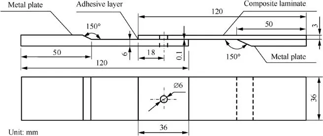
Fig. 1 Configuration and geometric parameters of specimens.
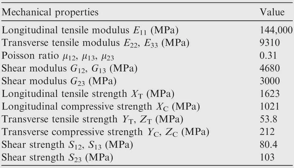
Table 1 Mechanical properties of T300/5228 ply.
2.2. Experimental test
All experimental tests were carried out on an Instron8801 100 kN electro-hydraulic and servo-controlled material testing machine at room temperature. A tensile load was applied at a constant displacement rate of 1 mm/min until the specimen failed.The load error is less than 1%.A 25 mm measuring scale extensometer was installed at the lateral side of the specimen to obtain bearing deformation of the bolted hole as shown in Fig.2.
3. FEm
3.1. Modelling
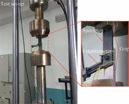
Fig. 2 Test set-up and extensometer installation.
Finite element analysis of the HBB joint was performed on ABAQUS software. Benefited from the symmetric geometry,only a half of the joint was modeled to save CPU time. The model consists of 4 parts,including composite laminate,metal plate,bolt(screw and nut are modeled as a whole with 0.5 mm diameter hole at the bolt center in order to obtain fine meshes),and adhesive layer.Cohesive element was ever used to simulate interfacial damage of the adhesive bonding by establishing two cohesive layers with 0 mm thickness between the adhesive and adherends.However,many tries showed that the computation is difficult to converge due to serious non-linear issues of the model and no satisfactory results were obtained. Therefore,cohesive element was not employed finally, and adhesive and adherends were tied together directly in the model.
Fig. 3 shows meshes, load and boundary conditions of the FEM. In the figure, UXand UZare displacement constraints along X- and Z-directions respectively; ΨX, ΨYare rotation constraints along X- and Y-directions respectively; and EYis boundary stiffness along Y-direction. All parts were meshed with 3D solid element C3D8R defined by eight nodes hexahedral reduced integration element with three degrees of freedom per node. The adhesive layer and each composite ply were meshed with one element along the thickness. Refined meshes were adopted in the bonded and bolted region to increase theaccuracy of stress and failure simulation.The model contained 38,660 meshes and 47,110 nodes in total.Symmetric boundary condition was applied on the symmetry planes. Fixed constraint was applied on the end of the metal plate (All=0 in the figure). Displacement load of UXwas applied on the end of the laminate.

Table 2 Mechanical properties of SY14-M, 45#steel and 304 stainless steel.
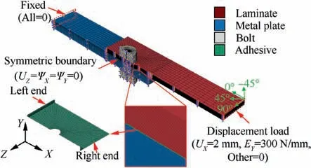
Fig. 3 FEM details of the HBB joint.
The adhesive fillets at ends of the bondline(see Fig.4)were considered in the FEM.Because the three specimens have different fillet shapes and sizes,the fillets of specimen A-1 were considered in the FEM as shown in Fig. 4. Lateral stiffness of the testing machine was also considered in the model due to its obvious effects on single-lap structure.23As the lateral stiffness of INSTRON 8801 is 300 N/mm,a spring with 300 N/mm stiffness along Y-direction was modeled at the loading end, which is denoted with EY=300 N/mm as shown in Fig.3.
A 3.5 N·m pre-tightening torque (equal to 2.9 kN tensile preload along the bolt axis) was applied on the bolt as shown in Fig. 4.Six surface-surface hard contact pairs,including: C1(bolt shank-laminate hole), C2 (bolt shank-adhesive hole), C3(bolt shank-metal plate hole), C4 (bolt head-laminate), C5(bolt head-metal plate) and C6 (laminate-metal plate), were created as shown in Fig. 4. C6 is set to simulate the friction between the adhesive and adherends after the adhesive fails.0.04 mm bolt-hole clearance was considered between the bolt and hole in the model.
3.2. Failure criteria and material property degradation rule
Failures of the composite laminates and the adhesive layer were considered in the FEM by choosing proper damage initiation and evolution criteria. Plasticity of the metal plate and bolt was considered in the FEM as well.
3.2.1. Composite material
Three dimensional Haszin failure criteria,24Chang fiber-shear failure criteria25and Ye delamination failure criteria26were employed to predict the different damage modes in the laminate, which are explained in detail as follows:
Fiber tensile failure (σ11>0):

Fiber compression failure (σ11<0):

Matrix tensile failure (σ22>0):

Matrix compression failure (σ22<0):

Fiber-matrix shear failure (σ11<0):
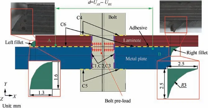
Fig. 4 Fillets, preload, contact pairs, and extensometer displacement in the FEM.

Delamination in tension (σ33>0):

Delamination in compression (σ33<0):

where σ11, σ22, σ33are normal stress components along longitudinal, transvers and thickness directions, respectively. σ12,σ13, σ23are shear stress components. XT, XCare tensile and compressive strengths along longitudinal direction. YT, YCare tensile and compressive strengths along transverse direction.ZT,ZCare tensile and compressive strengths along thickness direction. S12, S13, S23are shear strengths.
Once the stress state of an laminate element satisfies any of the above failure criteria,stiffness of the element is degraded to a certain value according to the degradation rules proposed by Camanho and Matthews27and Tserpes et al.28as listed in Table 3.
3.2.2. Adhesive layer
The failure of the adhesive layer was predicted by maximum tensile strain criterion which can be expressed using principle stress components as following:

where σris equivalent stress,σ1,σ2and σ3are maximum,medium and minimum principle stress respectively, and [σ] is allowable stress equals to the uniaxial tensile strength of the adhesive.
The adhesive failure criterion was chosen by considering the brittleness of SY-14M adhesive as shown in Fig. 5. There are two alternative criteria, maximum tensile stress criterion and maximum tensile strain criterion. Maximum tensile strain criterion is recommended when compressive stress is greater than tensile stress, while the condition is contrary for using maxi-mum tensile stress criterion. The bolt preload leads to a large compressive stress in the adhesive layer, but the effect is negligible in the fillets.Therefore,two cases were compared here.In case-1, maximum tensile strain criterion was used in both the adhesive and fillets;in case-2,maximum tensile stress criterion(σr=σ1≤was used in the fillets while maximum tensile strain criterion was used in other regions. The results showed a negligible difference between the two cases. Therefore, the maximum strain criterion was applied for the whole adhesive layer.
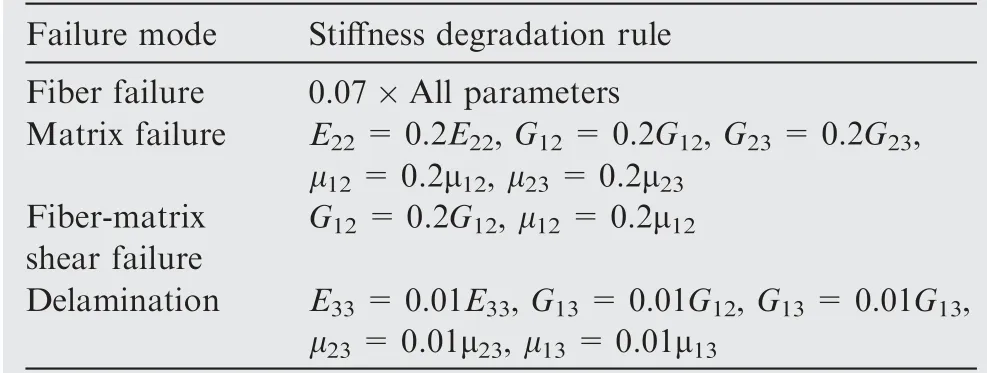
Table 3 Stiffness degradation rules of composite.
Once an adhesive element fails, its stiffness and Poisson ratio degrade to small values and the element totally loses the load transfer ability according to the following equations:

3.2.3. Bolt and metal plate
The metal plate (45# steel) and bolt (304 stainless steel) were considered as plastic materials. The stress–strain relationships of 45#steel and 304 stainless steel used in the model are shown in Fig. 5.
4. Results
4.1. Load–displacement curves
Experimental and numerical load–displacement curves are plotted in Fig. 6, in which A-1, A-2, A-3 are experimental results of the three specimens and FEM is numerical result.The displacement in curves refers to UAX–UBX=25 mm as marked in Fig. 4, corresponding to the extensometer results in the experiment (see Fig. 2). The initial damage load Lai(the load when the first sound was heard in the experiment,corresponding to the load when the initial damage occurs in the FE analysis), ultimate bonding load Lau(the highest load before the adhesive totally fails) and ultimate bolting load Lbu(the ultimate load after the adhesive fails) are listed in Table 4. As can be seen, Laiand Lauof the three specimens show large differences, which may result from the different adhesive fillet configurations, bolt-hole clearance or other factors.Lbuof the three specimens are almost the same.The load–displacement results of A-1 and FEM match well. Therefore,the FEM is validated to be effective.
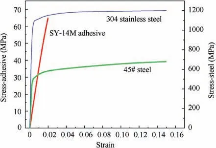
Fig. 5 Tensile property of SY-14M adhesive, 45# steel and 304 stainless steel.
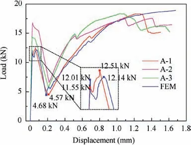
Fig.6 Experimental and numerical load–displacement results of joints.

Table 4 Experimental and numerical Lai, Lau and Lbu.
4.2. Failure morphology
The three specimens have almost the same failure morphologies. Fig. 7 shows the failure morphologies of both the specimens and the FEM. In view A-A of the laminate, yellow lines mark the fiber–matrix shear damage, green lines mark the delamination, red lines mark the fiber break and purple lines mark the matrix damage. The joint finally fails with the serious bearing crushing around the laminate hole edge and complete failure of the adhesive. There are damaged adhesive volumes at both surfaces of the metal plate and laminate.Yield deformation of the metal plate occurs around the bolt hole edge at the extruded side. The bolt has plastic bending deformation as well. The experimental and numerical damage results match well, thus the validity of the model is further proved.
4.3. Damage propagation
4.3.1. Adhesive damage propagation and analysis
Fig.8 presents the load sharing and adhesive damage propagation (red elements denote the damage). In the figure, Ljis the load carried by the HBB joint, Lbis the load carried by the bolt, including bearing load and friction force, Lbnis the bolt bearing load,d1is the load carried by the failed adhesive due to its small stiffness and d2is the friction force.
From Fig.8,the specific adhesive damage propagation process can be explained as follows (point A–F are marked in Fig. 8):
1) Before the damage occurs, the load–displacement curve is a straight line.The damage initiates from right end of the adhesive at point A and then propagates along the transvers direction to the lateral sides.
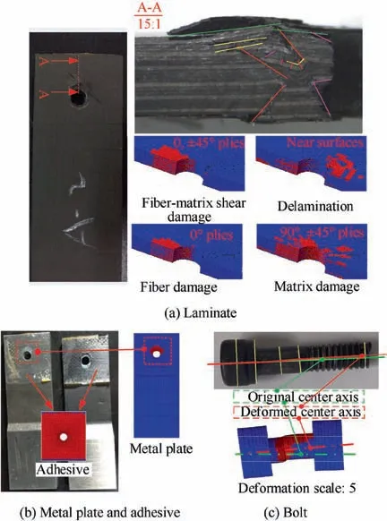
Fig. 7 Experimental and numerical damage morphologies.
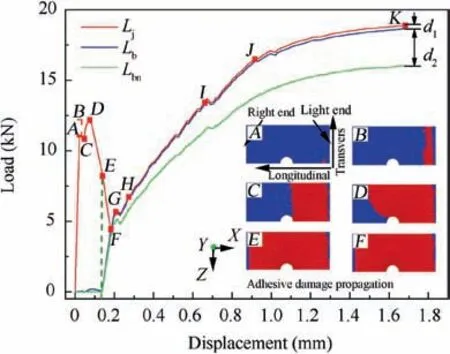
Fig. 8 Load sharing and adhesive damage propagation in the HBB joint.
2) Ljreaches the 1st peak at point B.The damage begins to propagate to left end of the adhesive along the longitudinal direction. Then Ljdecreases lightly.
3) Ljreaches the 1st valley at Point C. Correspondingly,the damage propagates to the vicinity of the hole and then propagating speed gradually becomes lower.
4) Ljreaches the 2nd peak at point D. Then the damage continues expanding to the left end with a faster speed and Ljdecreases quickly.
5) The adhesive is totally damaged at point E. The bolt begins to carry load and Ljcontinues decreasing quickly.After point E, Lbincreases rapidly.
6) Ljreaches the 2nd valley at point F. At this point, Ljis almost equal to Lb, which means the load is totally transferred by the bolt.
It can be concluded that before point F, the load is almost totally transferred by the adhesive layer and the joint performs like a pure bonded joint. After point F, the load is totally transferred by the bolt and the HBB joint performs as a pure bolted joint.Accordingly,the loading process of the HBB joint can be divided into two stages, adhesive–carries–load (ACL)stage and bolt–carries–load (BCL) stage.
d2has a large value at the BCL stage, indicating that the contact friction force plays an important role in load transfer.The friction force comes from three contact pairs including C1(bolt shank-laminate hole), C4 (bolt head-laminate) and C6(laminate-metal plate), and their corresponding loads are shown in Fig. 9. As can be seen, the friction force from C1 plays the most important role, which includes two parts as explained in Fig.10.One is caused by the bearing friction parallel to the joint plane and the other is caused by the bearing friction perpendicular to the joint plane. In Fig. 10, f denotes the friction force, and fx, fy, fzdenote the components of friction force along X-, Y- and Z-directions respectively.
Fig.11 shows the stress distribution along the adhesive centerline at point A,B and C(points in Fig.8).σXX,σYY,σZZare tensile stress components along X-, Y- and Z-directions, and σXY, σXZ, σYZare shear stress components. Note that σXZand σYZare not plotted in the figure due to their small values.At point A,tensile stress σXXand shear stress σXYare the main stress components around the adhesive ends.σYYshows a large compressive stress around the adhesive hole due to the bolt preload. It is worth mentioning that σZZshows a large value.σXYis still the most important stress component causing damage at point B.Comparing the stress distribution at point A,B and C, it can be found that local damage of the adhesive does not obviously change the stress status of the undamaged adhesive regions.
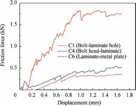
Fig. 9 Friction forces from C1, C4 and C6 in HBB joint.
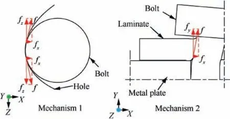
Fig. 10 Mechanisms of bolt-hole friction force.
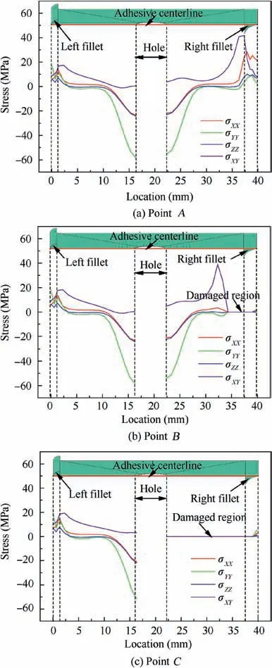
Fig.11 Stress distribution along the adhesive centerline at point A, B and C.
4.3.2. Laminate damage propagation
Morphologies of matrix-fiber shear damage, matrix damage,delamination and fiber damage in the laminate at point F, G,H and K (points in Fig. 8) are listed in Table 5. In the table,red elements denote the damage.
The matrix-fiber shear damage mainly occurs in 0°, ±45°plies, and the fiber damage mainly occurs in 0° plies. Both these two types of damage initiate at the compressed side of the hole and propagate along the thickness, longitudinal and circumferential directions.
The matrix damage mainly occurs in 90°and±45°plies at compressed side of the hole and in 90°and 45°plies at uncompressed side of the hole. This kind of damage initiates at theuncompressed side due to the tensile stress, and then quickly expands to the compressed side once the adhesive totally fails.
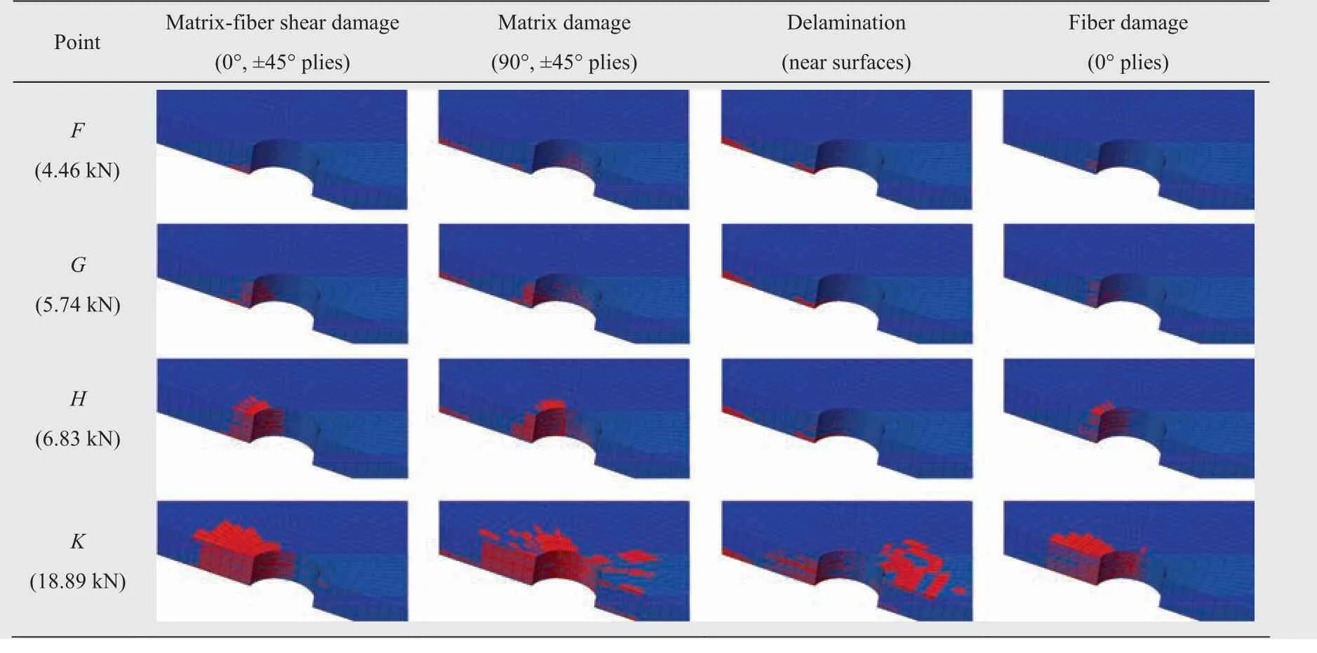
Table 5 Laminate damage propagation process.
The delamination initiates in the interfaces around the hole and is close to the bottom surface of the laminate bonded with the adhesive. Once the adhesive totally fails, the delamination gradually occurs in other interfaces due to bearing of the bolt shank. Different from other damage types, a large area of delamination occurs at the uncompressed side of the hole due to friction and compression of the bolt head when the specimen bends. Interface stresses between the two outermost laminate layers at uncompressed side of the hole, as shown in Fig. 12(a), are selected to explain the delamination mechanism. The interface stresses before delamination occurrence against the loading displacement are plotted in Fig. 12(b). As can be seen, σXZand σZZare the main stresses causing the delamination. Before the 1st peak load, σXZis mainly caused by the laminate bending.And after that,σXZis caused by both the laminate bending and the friction between the bolt head and laminate. σZZincreases after the 1st peak load due to the increase of compressive force of the bolt head.
4.3.3. Metal plate and bolt damage propagation
Plastic damages of the metal plate and bolt are shown in Table 6 (point F–K are marked in Fig. 8). Plastic damage of the metal plate initiates at the compressed hole edge at point F and then propagates along the longitudinal and circumferential directions. The large plastic region around the hole agrees well with the experimental results at point K. Plastic deformation of the bolt occurs later than that of the metal plate,which mainly results from the bending deformation.
To sum up, the numerical and experimental results of the load–displacement curves and damage morphologies match well, which proves the validation of the FEM. Some discussions can be conducted based on the FEM.
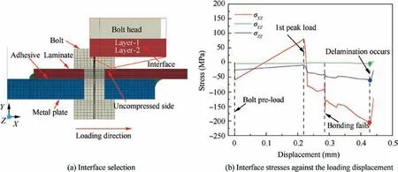
Fig. 12 Interface selection and interface stresses at the uncompressed side of the hole.
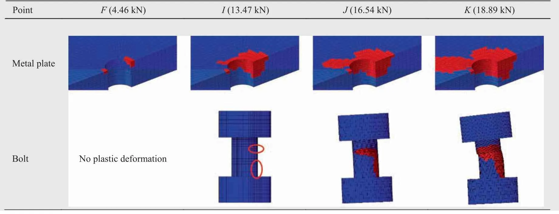
Table 6 Damage propagation in the metal plate and bolt. (Red elements denote the plastic region.)
5. Discussions
5.1. Comparison of different joint forms
Performances of clearance-fit and neat-fit HBB joints are compared with those of pure bonded and pure bolted joints in this section. The load–displacement curves are plotted in Fig. 13.The load, stiffness and energy absorption results are listed in Table 7, in which Siis the initial tensile stiffness of the joint,Ejis the energy absorption during the loading process and Ejais the energy absorption before the adhesive totally fails.
It can be concluded that the clearance-fit HBB joint is like a simple combination of pure bonded and pure bolted joints while the neat-fit HBB joint is not. This is because the bolt bears part of the load at ACL stage in the neat-fit HBB joint.Compared with the pure bonded joint, the ultimate bonding load (Lau) and energy absorption (Eja) at ACL stage of the neat-fit joint increase by 15.5% and 32.8%, respectively; the energy absorption (Ej) of HBB joint is almost 14 times that of pure bonded joint due to the great energy absorption capacity of bolt bearing. Compared with the pure bolted joint, the adhesive in the HBB joint increases the initial stiffness(Si),initial damage load(Lai)and energy absorption(Ej)of HBB joint by 75.9%,57.55%and 1.2%,respectively.Therefore,the HBB joint shows better performances than the pure bonded and pure bolted joints by providing multi-load transmission paths.
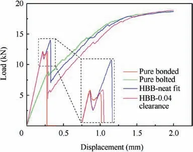
Fig. 13 Load–displacement curves of different joints (displacement refers to that at laminate end).
Additionally,the bolt obviously changes the adhesive damage propagation as shown in Fig. 14. The damaged volume ratio (solid line) is ratio of the damaged adhesive volume to the total adhesive volume.The damage expanding speed(dash line) is the first derivative of the damaged volume ratio versus displacement curve. As can be seen, the damage propagation process in both the pure bonded and HBB joints can be divided into three stages: first quickly expanding stage (stage A–B and A’–B’), slowly expanding stage (stage B–C and B’–C’) and second quickly expanding stage (stage C–D and C’–D’). In the first quickly expanding stage, the damage in the HBB joint expands more quickly than that in the pure bonded joint. In the slowly expanding stage, the damage propagation in the HBB joint takes much more displacement than that in the pure bonded joint. And in the second quickly expanding stage, the damage in the HBB joint expands more slowly than that in the pure bonded joint. The damage propagation process indicates that the HBB joint has great damage tolerance and damage resistance.
5.2. Effect of adhesive fillets
To author’s knowledge,only Kelly10,11established adhesive fillets in HBB joint model but didn’t discuss their effects.In practice, adhesive fillets are common in bonded structures. In this section, effects of the adhesive fillets on HBB joint performances are discussed by comparing four FEMs with different fillets as listed in Table 8. In the table, ‘●’ means there is corresponding left or right fillet in the joint while ‘-’ means there is no corresponding fillet.The sizes and shapes of the fillets are shown in Fig. 4.
Fig.15 shows the effects of the left and right adhesive fillets.The performance values of J_NF are set as unit one,and other values are relative values of J_NF. As can be seen, the fillets can improve the HBB joint performances overall. Specifically,the right fillet improves the initial damage load (Lai) and the left fillet improves the ultimate bonding load (Lau); both theleft and right fillets improve the energy absorption capacity(Eja).The fillets show small effects on the ultimate bolting load(Lbu) and stiffness (Si).

Table 7 Load, stiffness and energy absorption of different joints.

Fig. 14 Adhesive damage propagation process in pure bonded and neat-fit HBB joints.

Table 8 Arrangement of the adhesive fillets in the four HBB joint FEMs.
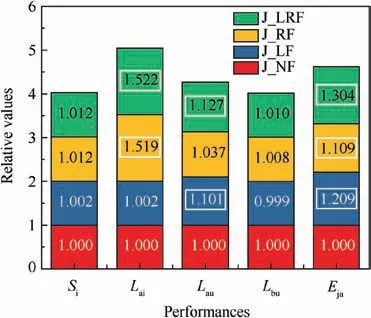
Fig.15 Performance comparisons for joints with different fillets.
The contributions of the adhesive fillets can be explained by Fig. 16. Compared with the J_NF, the fillets in J_LRF reduce the stress at right end of the adhesive (point A in Fig. 16) by 40.5% and reduce the stress at the left end (point B) by 22.0%when the applied load is 7 kN.This is because the fillets obviously increase the bonding area and reduce the stiffness mutation at the adhesive ends.
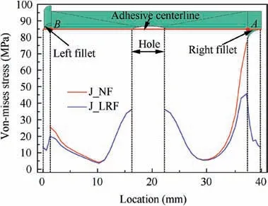
Fig. 16 Von-Mises stress distribution along adhesive centerline in J_NF and J_LRF under load of 7 kN.
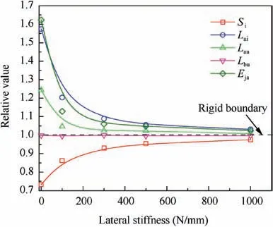
Fig. 17 Effects of boundary lateral stiffness.
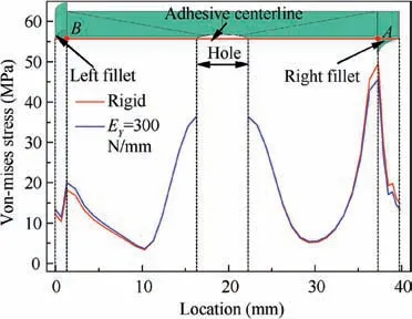
Fig. 18 Von-Mises stress distribution along adhesive centerline in situations of rigid and EY=300 N/mm under load of 7 kN.
5.3. Lateral stiffness of boundary
Lateral stiffness of testing machine is found to have a large effect on bending deformation of single-lap bolted joint while has no effect on bolted joint strength.23However, bending deformation may lead to a decrease of HBB joint strength by increasing peeling stress. In this section, six lateral stiffnesses including 0 N/mm, 100 N/mm, 300 N/mm, 500 N/mm,1000 N/mm and fully rigid are considered.
The relationships between the lateral stiffness and joint performances are plotted in Fig. 17. The performance values in rigid situation are set as unit one,and other values are relative values of the rigid one.It can be concluded that decreasing lateral stiffness will improve the bonding strength (Laiand Lau)and energy absorption capacity (Eja) but reduce the tensile stiffness (Si). Similar to the conclusion of bolted joint, lateral stiffness shows a small effect on the ultimate bolting strength(Lbu).
The effects of the lateral stiffness can be explained by Fig. 18. Smaller lateral stiffness decreases the stress at right end of the adhesive(point A in Fig.18)by 7.9%but increases the stress at the left end (point B) by 10.4%. This is because smaller lateral stiffness reduces the joint bending deformation.Therefore, smaller lateral stiffness of the boundary makes the adhesive stress distribution more uniform and then improves the joint strength and energy absorption capacity. However,smaller bending deformation results in a larger axial deformation and then reduces the joint tensile stiffness. Moreover,boundary of HBB joint is not fully rigid in practice, considering lateral stiffness of the boundary in design and analysis of single-lap HBB joint can obtain more accurate results.
6. Conclusions
In this paper, tensile performances of a composite–metal single-lap HBB joint were studied experimentally. Then a detailed FEM of the joint was established and proved by the experiments.Loading process,load sharing,stress distribution and damage propagation were investigated based on the FEM.Finally, tensile behaviors of HBB, pure bonded and pure bolted joints were compared and the effects of adhesive fillets and boundary lateral stiffness are discussed.Some conclusions can be drawn as following:
1) Tensile behavior of the HBB joint can be divided into two stages: adhesive–carries–load (ACL) stage and bolt–carries–load(BCL)stage.The load is mainly transferred through the adhesive at ACL stage,while the load is totally transferred through the bolt at BCL stage.
2) The adhesive damage mainly results from shear stress and longitudinal tensile stress. The damaged adhesive regions do not obviously change stress status of the undamaged regions. The damages in the laminate and metal plate initiate from the hole edge and then propagate along the thickness,hole circumference and longitudinal directions. The plastic deformation of the bolt mainly results from the bending force.
3) Friction forces have obvious effects on the load transfer.Friction force between the bolt shank and hole plays the most important role among all the contact friction forces.
4) The HBB joint provides multi-load transmission paths and damage resistance. Clearance-fit bolt-hole relationship should be avoided.The HBB joint has much greater energy absorption capacity than the pure bonded joint and shows larger initial damage load and tensile stiffness than the pure bolted joint.
5) Adhesive fillets can improve tensile performances of the HBB joint by increasing bonding area and reducing stiffness mutation. Lateral stiffness of testing machine and joint boundary show obvious effects on tensile performances of single-lap hybrid joint and should be considered in joint design and analysis.
 CHINESE JOURNAL OF AERONAUTICS2021年2期
- CHINESE JOURNAL OF AERONAUTICS的其它文章
- Recent active thermal management technologies for the development of energy-optimized aerospace vehicles in China
- Electrochemical machining of complex components of aero-engines: Developments, trends, and technological advances
- Recent progress of residual stress measurement methods: A review
- Micromanufacturing technologies of compact heat exchangers for hypersonic precooled airbreathing propulsion: A review
- Towards intelligent design optimization: Progress and challenge of design optimization theories and technologies for plastic forming
- A combined technique of Kalman filter, artificial neural network and fuzzy logic for gas turbines and signal fault isolation
