Pseudo-linear inertial navigation algorithm
Habib GHANBARPOURASL
Department of Mechatronics, University of Turkish Aeronautical Association, Ankara 06790, Turkey
KEYWORDS Inertial navigation algorithm;Integrating algorithm;Position quaternion;Pseudo-linear inertial navigation equation;Quaternions;Velocity quaternion
Abstract A new method is illustrated for processing the output of a set of triad orthogonal rate gyros and accelerometers to reconstruct vehicle navigation parameters(attitude,velocity,and position).The paper introduces two vectors with dimensions 4×1 as velocity and position quaternions.The navigation equations for strapdown systems are nonlinear but after using these parameters,the navigation equations are converted into a pseudo-linear system. The new set of navigation equations has an analytical solution and the state transition matrix is used to solve the linear timevarying differential equations through time series. The navigation parameters are updated using the new formulation for strapdown navigation equations. Finally, the quaternions of velocity and position are converted into the original position and velocity vectors. The combination of the coning motion and a translational oscillatory trajectory is used to evaluate the accuracy of the proposed algorithm.The simulations show significant improvement in the accuracy of the inertial navigation system, which is achieved through the mentioned algorithm.
1. Introduction
In the Inertial Navigation Systems(INSs),there are four categories of the sources of errors,including sensors’errors,initial condition errors, gravity modeling errors, and digital integrating errors, which are the main sources of error in the INS.1,2Sensor errors are linked to the quality of sensors, but repeatable errors can be reduced by a calibrating process and the compensating errors of sensors.2,3Initial condition errors are another source of errors and they can be divided into initial attitude,velocity, and position errors.Many of the navigation grad systems can automatically align themselves on the ground but their initial position is provided by external measurements,which cause errors in the INS.4The INS needs to have a model of gravity because the accelerometers measure only the specific accelerations but not the total accelerations, and it is another source of error.1–3Originally, the strapdown navigation equations were formulated in the 1950s,which are continuous-time differential equations, but for programming the navigation systems,we need to discretize this type of equations,3but then,it will become another source of error in the INS. The digitalization of the navigation equations first focuses on attitude algorithms.5Between 1950 and 1960, there were two popular methods, which include applying first-order algorithms with high-speed updates (10–20 kHz), and using higher-order algorithms with low-frequency updates (50–100 Hz).5Wilcox6and McKern7introduced Picard-type successive integration8using savage and third-order algorithms. Some researchers focused on updating the rotation vector. Gilmore updated the high-frequency rotation vector,9Miller worked on the seconddegree fitting polynomial on gyros data and then updated the rotation vector10while Lee et al. followed Miller’s works with more data.11
In recent years,another round of attitude algorithms’optimization has been started. Savage introduced an optimal explicitly matching approach to obtain the desired response of conning input amplitude, which is a function of its frequency.12Wang et al.proposed a higher-order rotation vector that was updated by considering the third13and fourth14order approaches to Picard’s component solution to a rotation vector. Wu et al.15,16worked on the attitude integration applying different methods. These methods are using Chebyshev polynomials, Rodrigues vector, and functional iterations. Iterative integration of the quaternions using Chebyshev polynomials has been filed in Ref.,17and that using a higher-order polynomial approach is given in Ref.18The application of Taylor’s series approach and comparison with functional iteration integration for quaternions is given in Ref.19
A two-speed updating algorithm for velocity and position integrating with inspiration of attitude algorithms is introduced by Savage in Ref.20He presented his analytical approach to sculling motion in two forms and used the algorithm with scrolling terminology while Litmanovich used his algorithm with more data; hence, his algorithm continued to be an accepted algorithm by various navigation communities.21Sculling integral is a critical part of updating velocity and position. Ref.22adapted sculling integral with different sensor inputs like angular rate/specific force increments’ input and the incremental angle/specific force input.Ref.23shows a new algorithm based on the sculling-error compensation approach, which was proposed for vibrating environments.Instead of polynomial models, it uses a singular perturbation model. Wu proposed a functional iterative integration-based method applying Chebyshev polynomials and named it iNavFIter.24
This paper introduces two new parameters including velocity and position quaternions. The mentioned parameters are different from dual quaternions, which are used in a previous research work.25The new parameters help us reduce the nonlinearities that emerge from the transformation of specific forces from the body frame to the inertial frame. Quaternions helped to introduce a new formulation for INS differential equations; however, the number of states increased from 10 to 12. The new equations behave as a linear time-varying system, so the problem can be solved using different methods. In this paper, a time series approach is used to find a solution to linear time-varying differential equations. For comparison of the proposed algorithm,a well-known algorithm called Savage algorithm has been used,5,20which operates in the navigation frame. The inertial frame version of Savage algorithm is filed in Ref.26The application of careful implementation of inertial navigation algorithm and its application in transfer alignment are given in Ref.27
2. Inertial navigation equation
Some important reference frames have to be defined to come up with navigation equations.The inertial frame is represented by i,and it is centered at the Earth’s center,the x-y plane is on the equatorial plane,the z axis coincides with the Earth’s rotation vector, and the x axis coincides with the vernal equinox axis 2. The body frame is represented by b, which is located in the aircraft’s center of gravity while all the mentioned axes are respectively heading in the longitudinal, right-wing, and downward directions.1All reference frames are considered as right-hand frames.
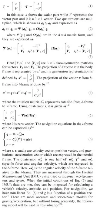
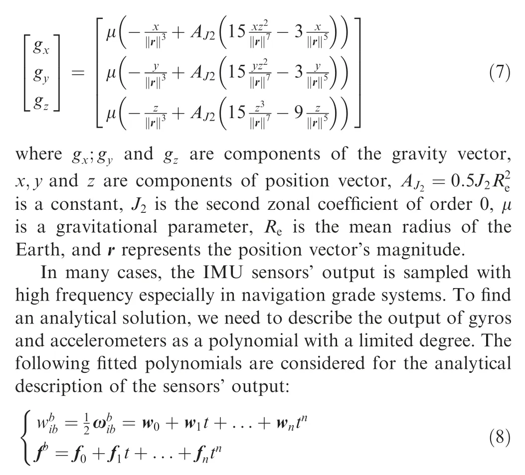
Most of the inertial navigation algorithms use quaternions for attitude computation. Quaternions are four parameters and they have some advantages for other attitude representation methods like Euler’s angles, rotation vector, and Direction Cosine Matrix (DCM). In this paper, we will show a quaternion in vector formation, which is given as
3. New formulation of navigation equation
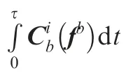
Multiplying two sides of the differential equations of velocity, and position, which are given in Eq. (6), we can write
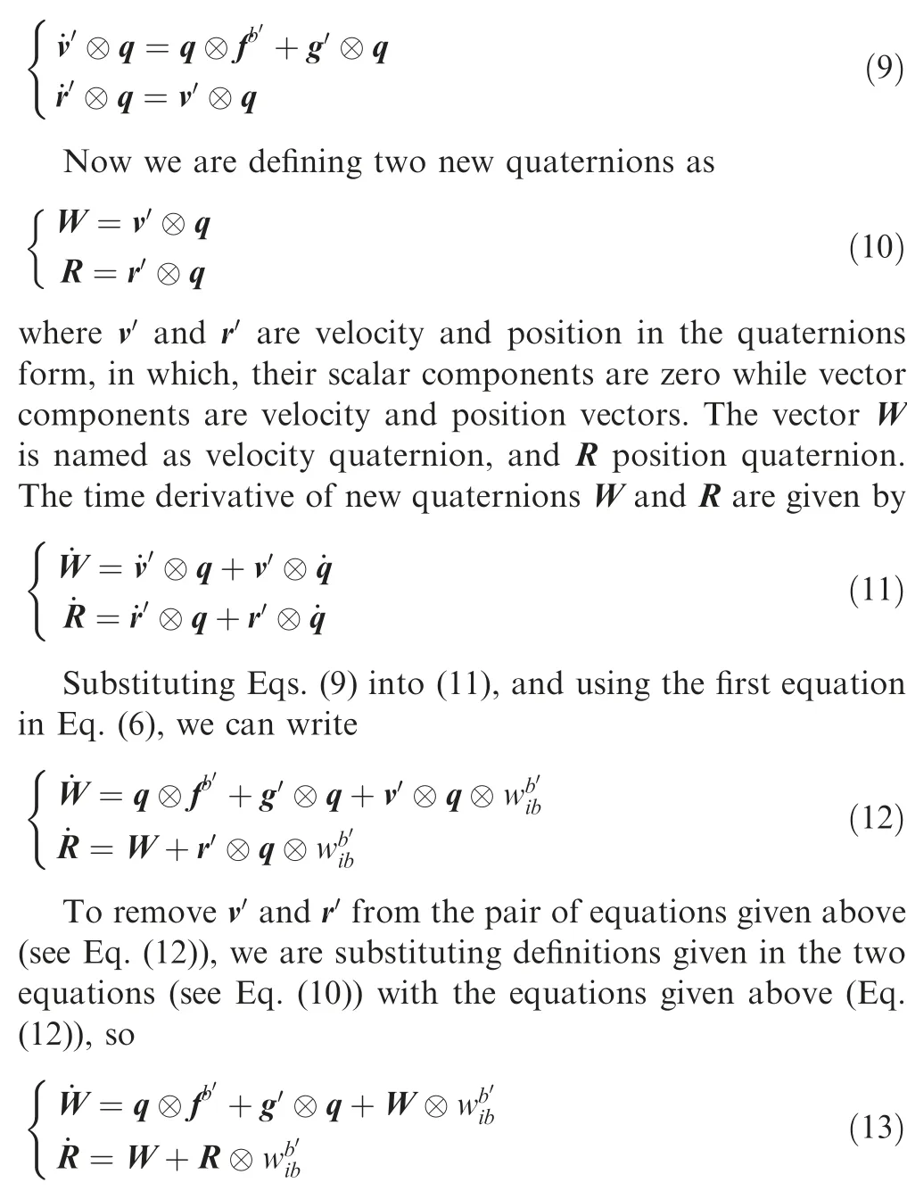
All terms in the two equations (see Eq. (13)) are pseudolinear except for the g′⊗q term. Here, g is a non-linear function of the position vector. For its compatibility with other terms to diminish the non-linearity problem with the new model, we have rearranged the gravity vector as

where β is a scalar function of r,and d has the remaining terms of the model (7), which are not in the term given above (14),and it is a vector in the inertial frame. Here β and d are represented in the model by Eq. (7), so it will become

where α is a scalar parameter and a function of position vector. Finally, using Eqs. (13) and (14), and the first part of Eq.(6), the navigation equations in the inertial frame are summarized as

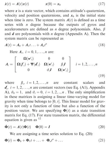
where I is a 4×4 unit matrix, and d is a small disturbance input. This form of equations in this paper are termed as pseudo-linear navigation equations. In the state space (Eq.(16)), there are 12 states and the system matrix is a function of IMU’s output, but it still has nonlinearities connected to the gravity vector. One way to surpass this problem (avoiding nonlinearities)is by evaluating the gravity’s parameters at time zero, but they will cause more errors. The system matrix is a function of position but in short time, we can suppose that it is a linear function of position. To completely remove this error, a time-varying linear model has been provided for β and d in Appendix A. Using that process, we are trying to remove any existing non-linearity in the system. It is given in the matrix form in Eq. (16). We wish that the model shows good numerical properties because of linear behavior of the dynamic system.
4. Approximation of state transition matrix
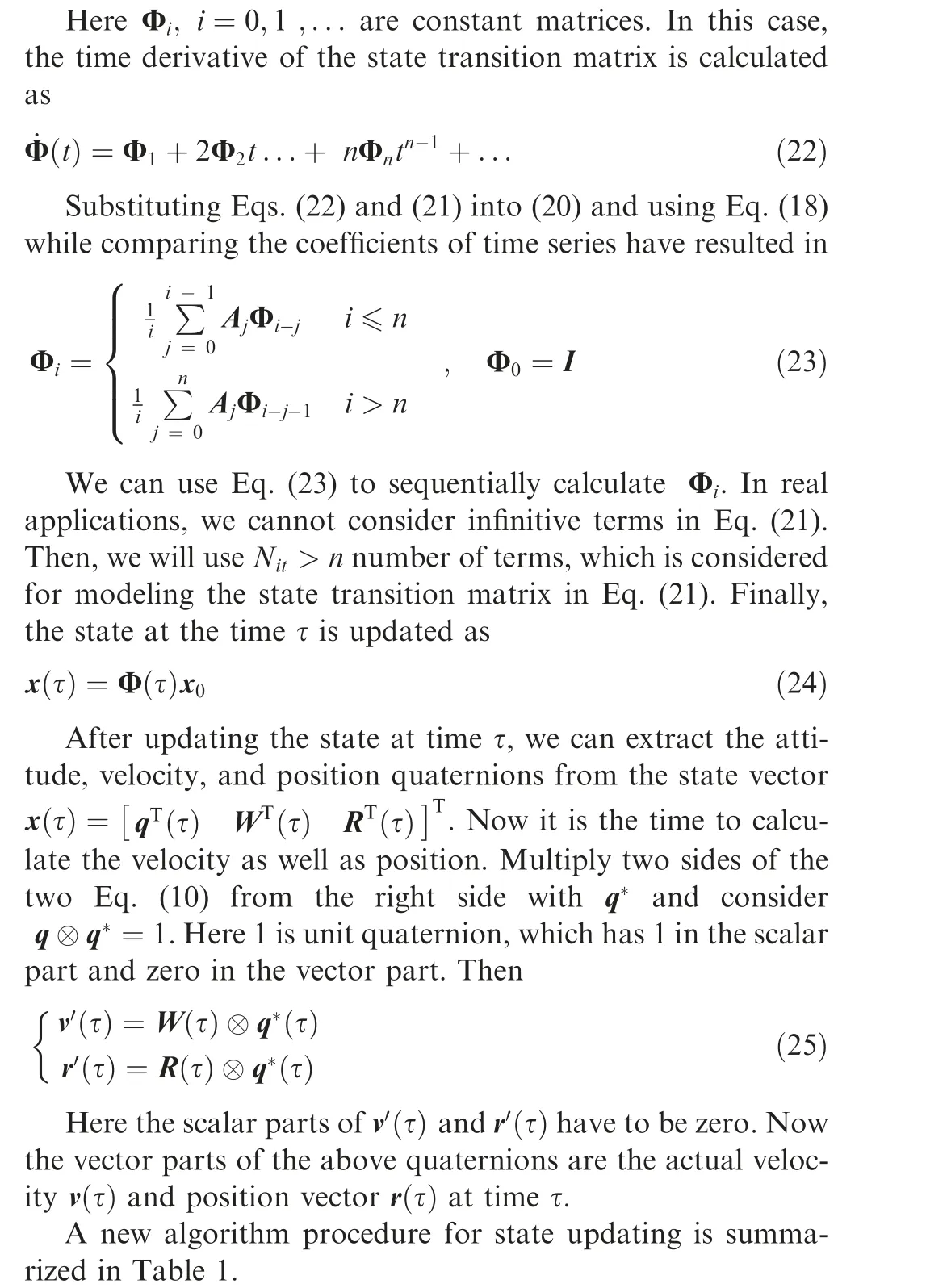
Now, we are representing Eq. (16) as a linear time-varying system:
5. Error analysis
For error analysis, we will use the Taylor series expansion of the state transition matrix.Using Leibniz formula,we can calculate the time derivative of Eq. (20) as29
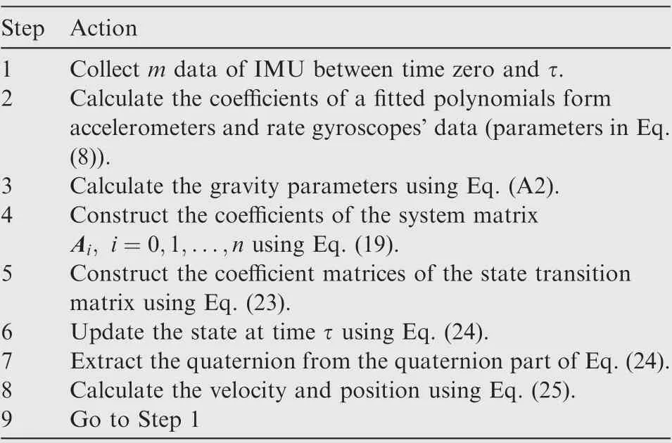
Table 1 INS procedure.
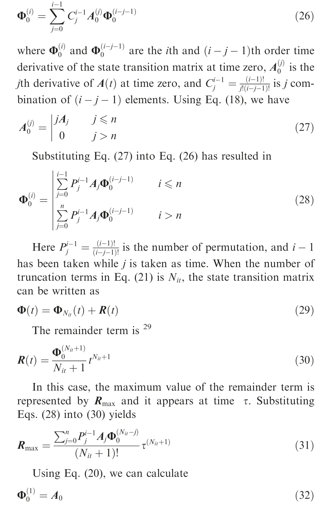
Recursively using Eq.(28)and initializing with Eq.(32),we can calculate the maximum error of the state transition matrix.Using Eq. (5), we can see, when Nit→∞;Rmax→0. Using Eqs. (24) and (31), we can calculate the maximum state error at time τ for Nitterms in Eq.(21),and we consider the following state error at time τ:

6. Savage algorithm
For comparison of the proposed algorithm’s performance, we are considering the Savage’s algorithm,5,20which is accepted as a standard algorithm by the navigation community. The original algorithm is implemented in the navigation frame but the inertial frame implementation version is given in Ref.28The incremental angle and velocity are defined as

where Δθkand Δvkare incremental angle and velocity respectively.Incremental rotation vector between times tk-1and tkis given in Ref.28as
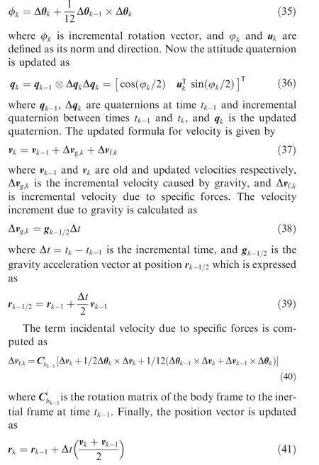
The Savage algorithm uses Eqs. (36), (37) and (41) for navigation.
7. Simulation study
For evaluating the performance of the proposed algorithm,we need to design a reference trajectory with known attitude,position, and velocity such that the angular velocities and specific accelerations for motion are known. Here we are defining two reference trajectories, in which, both of them have analytical solutions. We used a combination of classic coning motion for the body with a straight line translational motion as a first reference trajectory. The second one is a combination of conning motion and oscillating translational motion. The classic coning motion has an analytical solution and simply, we can evaluate the performance of the attitude algorithms. The classic coning motion has a specific angular velocity,which is given below24:

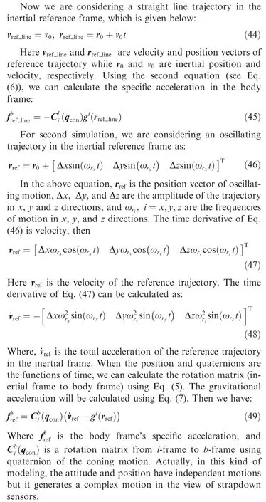
For evaluating the potential of new formulation,two examples have been solved to show the performance of the algorithm. The simulations are done for one-hour duration with an ideal IMU. The sampling frequency for IMU’s sensors is 1 kHz, and the navigation parameters are updated at 100 Hz frequency. An 8-degree polynomial has been used for interpolating angular velocity and specific acceleration vectors. The incremental angles and velocities are calculated using fitted polynomials on angular velocities and specific accelerations described by a system of equations (see Eq. (8), and Eq.(34)), and then they have 100 Hz updating frequencies. The simulations are started with 30° and 60° right ascension and declination (relative to the inertial axis) with 10000 km altitude. The parameters of gravity are approximately used in the second-order Eq.(A1).Table 2 shows the straight line simulation parameters.
The left side of Fig. 1 illustrates the coning motion’s angular velocity, which is constant in the×axis and oscillates in y and z directions at π rad/s frequencies.The right side of Fig.1 shows the quaternion components.
The period of ωyand ωzis 2 s with the magnitudes of 31.25°. and ωxhas constant value -2.734°. Fig. 2 shows the components of the nominal specific acceleration vector in three directions and its zoomed graphs for slight line trajectory.
We can see that all the components of specific accelerations are oscillatory in short time due to coning motion and its magnitude reduces in long time because the altitude is increasing.Figs.3–5 represent position error ei(i=x,y,z),velocity error evi(i=x, y, z) and quaternion error error eqi(i=1, 2, 3, 4),respectively, for both proposed and Savage algorithms.
It can be observed that the maximum position error in one hour for the proposed method is 0.16 mm, and for Savage algorithm, it is 1.01 km. The maximum velocity errors for the proposed and Savage algorithms are 0.2 mm/s and 1.25 m/s, respectively. Maximum attitude error for the proposed algorithm is 4×10⁻⁸arcsec, but for Savage algorithm,it is 0.61 arcsec.
In the first example, the maximum magnitude of specific acceleration is 1g.In the second example, we want to examine the errors of algorithms when specific accelerations are highly oscillatory. The simulation parameters are represented in Table 3.
The coning motion’s parameters are the same for both simulations. The specific accelerations for oscillatory motion in the body frame are represented in Fig. 6.
Fig. 6 clearly shows that high-frequency oscillations in the specific accelerations originate from the coning motion but the low-frequency oscillations take place due to the oscillatory path. The maximum fx;fy, and fzare 97.08 m/s2, 60.38 m/s2,and 23.91 m/s2respectively. The oscillatory reference trajectory has different magnitudes in x, y, and z directions, such as 50 km,10 km, and 6 km in x, y, and z axes.
For imagining the complexity of the reference path, the designed path is shown relative to the starting point in Fig.7.The total velocity is in an oscillating state.Its minimum value is 420 m/s and the maximum is 2192 m/s.The proposed and Savage algorithms are successfully implemented in the MATLAB environment and the error of the position vector is shown in Fig. 8.
Fig. 8 shows that the maximum error of position exists in three directions within one hour, and it remains lower than 2 mm,but for Savage algorithm,it is 1.66 km.This is a significant improvement in the inertial navigation accuracy. Fig. 9 shows the velocity error in the inertial frame.
Velocity error for the proposed algorithm remains less than 5×10⁻⁶m/s but maximum error of Savage algorithm for total velocity is 2.9 m/s. That is a ‘‘bit error” for the inertial navigation system.
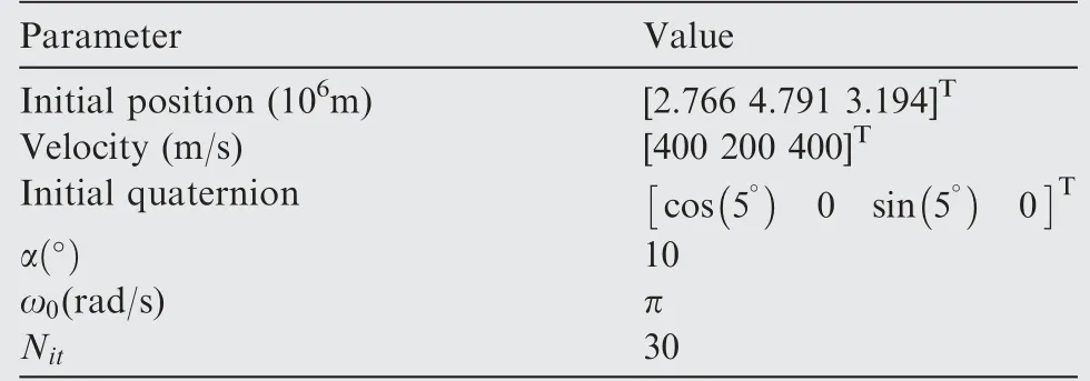
Table 2 Simulation parameters for straight line trajectory.
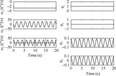
Fig. 1 Nominal angular velocities and quaternions for coning motion.
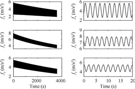
Fig. 2 Specific acceleration for straight line reference trajectory.
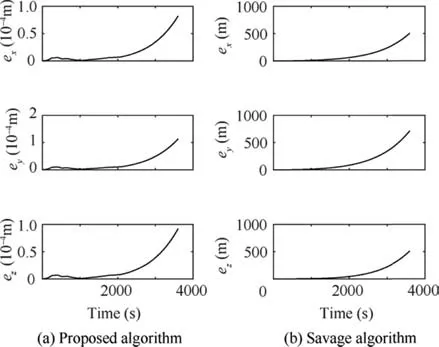
Fig.3 Position error for straight line reference trajectory by two methods.
In Fig.10,we can see that the errors of the quaternions are very close to zero. In that case, the rotation angle’s error is 8×10⁻⁸arcsec but the maximum error of rotation angle for Savage algorithm is 1.15 arcsec.We know that the first components of v′and r′are zero. After converting the quaternions’velocity and position, errors are accumulated in the first element of estimated v′and r′using mathematical equations(see Eq.(25)).These errors are represented in Fig.11 and they show unstable behavior of these parameters.
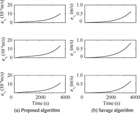
Fig.4 Velocity error for straight line reference trajectory by two methods.
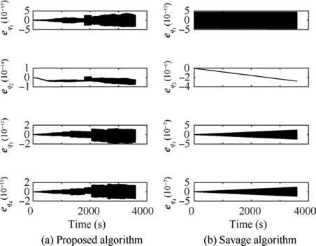
Fig. 5 Quaternion error for straight line reference trajectory by two methods.

Table 3 Simulation parameters for oscillatory trajectory.
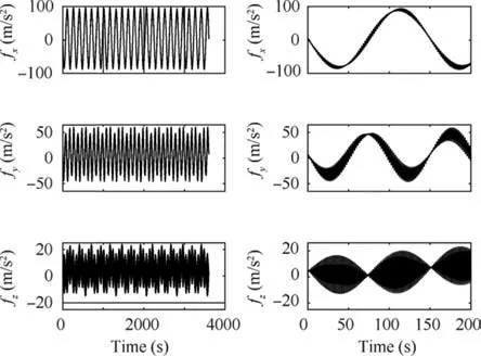
Fig. 6 Specific acceleration of oscillatory reference trajectory.
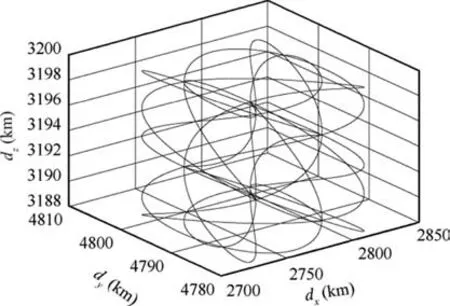
Fig. 7 Oscillatory reference path.
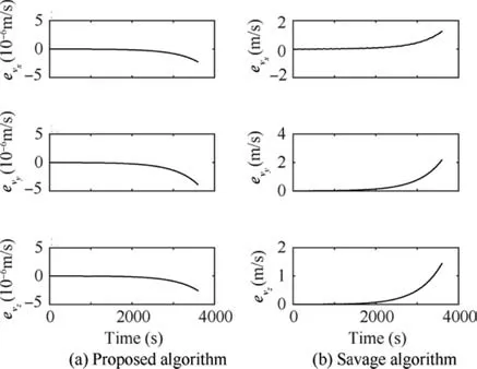
Fig. 9 Components of velocity error for oscillatory reference path by two methods.
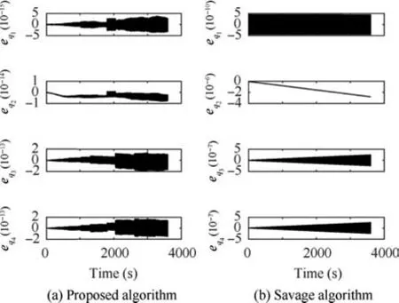
Fig. 10 Components of quaternions’ error for oscillatory reference path by two methods.
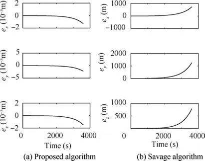
Fig. 8 Position error for oscillatory reference path by two methods.
For all simulations,we use a PC with an Intel(R)Core(TM)i5-2450 M CPU @ 2.50 GHz, 4 GB RAM, and MATLAB-2017b.
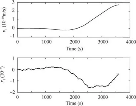
Fig. 11 First element of velocity and position quaternions.
8. Conclusions
In this paper, we design a new method for an ultra-accurate algorithm for application in the inertial navigation systems.This new algorithm uses some newly-defined parameters including velocity and position quaternions. These parameters transform the nonlinear navigation state equations into linear time-varying equations,which are further solved using the time series approach. A trajectory is designed for evaluating the algorithm, which has an analytical solution keeping in view specific forces and angular rates. The designed trajectory is a smooth oscillatory trajectory and it is generated by a combination of classic coning motion and a translational oscillatory trajectory. By tuning the parameters, it is possible to generate a path with different frequencies and amplitudes. Simulations show that the algorithm can be significantly improved in terms of numerical integration of the inertial navigation systems.It is shown that, for a difficult trajectory, the proposed algorithm has almost 100 m/s2specific acceleration,1800 m/s amplitude of the oscillatory velocity, and almost 42 angular velocity within one hour with less than 2 mm errors.
Appendix A.
One of the error sources in the velocity integration algorithms is integrating gravitational acceleration,which is a function of position. Savage used the middle point to calculate the integration of gravity vector.20This paper uses a special representation of the gravity vector. It is completely fitted with the model, which is used in this paper. As it is represented in Eq.(14), there are two functionsand. They are not the explicit functions of time. Here, we are considering an approximated polynomial with n degree, such as
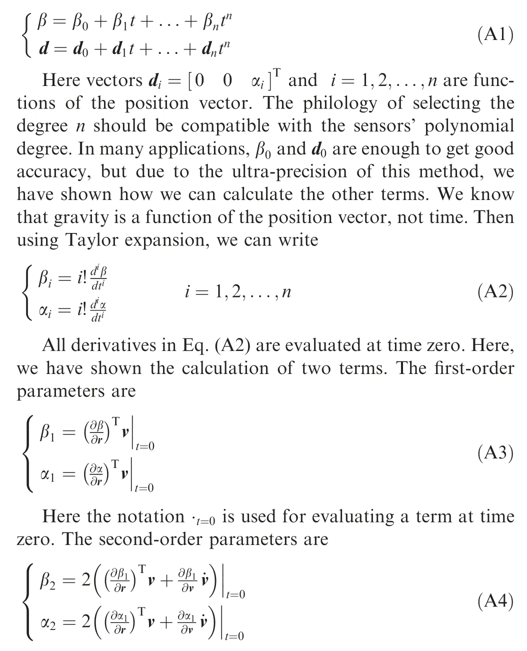
Here all the time derivatives are evaluated at time zero. In the above equations, the total acceleration ˙v has to be evaluated at time zero, and we can calculate it using the second equation of the two equations (see Eq. (6)) mentioned earlier.

 CHINESE JOURNAL OF AERONAUTICS2021年2期
- CHINESE JOURNAL OF AERONAUTICS的其它文章
- Recent active thermal management technologies for the development of energy-optimized aerospace vehicles in China
- Electrochemical machining of complex components of aero-engines: Developments, trends, and technological advances
- Recent progress of residual stress measurement methods: A review
- Micromanufacturing technologies of compact heat exchangers for hypersonic precooled airbreathing propulsion: A review
- Towards intelligent design optimization: Progress and challenge of design optimization theories and technologies for plastic forming
- A combined technique of Kalman filter, artificial neural network and fuzzy logic for gas turbines and signal fault isolation
