A Lamb wave quantification model for inclined cracks with experimental validation
Jingjing HE, Hode HUO, Xuefei GUAN, Jinsong YANG
a School of Reliability and Systems Engineering, Beihang University, Beijing 100083, China b Graduate School of China Academy of Engineering Physics, Beijing 100193, China
c CAD/CAM Institute, Central South University, Changsha 410083, China
KEYWORDS Crack orientation;Crack size quantification model;Incident angle;Lamb wave;Probability of reliable quantification (PRQ)
Abstract This paper investigates the influence of crack orientation on damage quantification using Lamb wave in plate structures.Finite element simulation is performed to acquire Lamb wave signal responses for different configurations of crack orientations and crack lengths.Two Lamb wave features,namely the normalized amplitude and the phase change,are used as damage sensitive features to develop a crack size quantification model. A hypothesis based on the geometrical influence on signal features is proposed, and the crack size quantification model incorporating the orientation angle is established using the hypothesis. An index of Probability of Reliable Quantification(PRQ) is proposed to evaluate the performance of the model. The index can be used to determine the sizing risk in terms of probabilities.A realistic aluminum plate is used to obtain the experimental data using piezoelectric (PZT) wafer-type sensors around a center through crack. The experimental data are used to validate the overall method. Results indicate that the proposed model can yield reliable results for size quantification of inclined cracks.
1. Introduction
As one of the important guided ultrasonic waves, Lamb wave has been proven to be one of the promising candidates for damage identification and quantification in metal and composite plate-like structures1–6. Lamb waves are a form of elastic perturbation and two basic modes of Lamb waves can be distinguished in a homogenous, isotropic plate-like structure,namely symmetric and anti-symmetric modes. Lamb waves have the advantages of strong penetration and minimal attenuation over a long distance. The wave characteristics are sensitive to discontinues along the propagation paths.Discontinuities such as cracks and corrosion pits etc. along the wave path can alter the characteristics of Lamb waves.Therefore, the existence of damage and the subsequent quantification of damage can be made by analyzing changes of the characteristics of Lamb wave.Wang and Chang7proposed a diagnostic technique for anomaly detection and localization using piezoelectric actuators and sensors in isotropic plates.The technique uses a built-in network of piezoelectric actuators and sensors to generate and receive Lamb waves over a wide range of frequencies. Lowe et al.8investigated the transmission of Lamb waves across adhesively bonded lap joints using finite element method (FEM). Three modes(S0, A0, and A1) of Lamb waves were studied in parallel aluminum sheets bonded with epoxy adhesives. He et al.9developed a multi-feature fatigue crack length estimation model using three damage sensitive features of the Lamb wave,namely, the correlation coefficient, the amplitude change,and the phase change. The authors confirmed that the multifeature model outperforms single-feature models in terms of sizing accuracy. Qiu et al.10presented a series of quantitative damage monitoring method, including damage occurrence,number, location, and size estimation. Hua et al.11developed a damage identification method based on extended dictionary construction. The advantage of their proposed method is the ability of forming damage outline for quantitative evaluation.Lu et al.12investigated the relationship between crack length and the reflection/transmission coefficient, through which the crack length was quantitatively evaluated. De Fenza et al.13presented a method of damage detection based on an artificial neural network and probability ellipse method using simulated data Lamb wave. The authors showed that the amplitude of the damage indices provides additional information about the inspection sensitivity. The development of damage assessment methods using Lamb wave can be found in, but may not be limited to, some recent surveys14–17.
Although many studies on damage assessment using Lamb wave have been reported,there are still challenges in achieving a robust and generic damage quantification model due to the following factors, such as versatile geometry features of targets, unknown damage orientations, uncertain data acquisition, and inconsistent data processing and interpretation for different targets. One of the uncertainty sources for crack quantification using Lamb wave is that an actual crack may not initiate or propagate as expected to favor the sensor arrangement. In particular, the locations of pre-installed sensors are usually based on assumed potential damage areas;however, crack initiation and propagation can be highly stochastic. The crack can grow in an unexpected direction in most cases. For example, aircraft components may consist of hundreds of rivets,around which cracks are susceptible to initiate18–20.The arrangement of the actuating and receiving sensors is usually perpendicular to the line between two rivets in SHM applications. In these cases a crack may not grow in a straight line due to the multi-axial loads or materials nonuniformity21–24,therefore,treating the crack as an ideal horizontal one can introduce uncertainties in size quantification25. The influence of the crack orientation on size quantification is of great importance for fatigue life assessment. Chang and Mal26developed a method of crack orientation estimation by analyzing the time and frequency spectra of Lamb waves scattering around edge cracks. Lu et al.27studied the distribution of the reflection/transmission features around a crack under different angles of incidence using finite element simulation and experimental data. In their study, the incident angle was defined as the angle between the incident direction and the vertical axis of a pair of sensors. It was found that the transmission coefficient increases as the incident angle increases, and the reflection coefficient decreases as the incident angle increases.An interpolation was given to correlate the two coefficients with the incident angle.Other techniques for crack orientation estimation include pattern-based approach28,spectrabased approach29, as well as frequency based approach30. To the best knowledge of the authors, few studies are reported to provide a Lamb wave-based quantification model for cracks incorporating the incident angle. The purpose of this study is to investigate the influence of the crack orientation on the Lamb wave signal features, and develop a Lamb wave-based quantification model for inclined cracks.
The rest of this paper is organized as follows. First, the influence of the crack orientation on the Lamb wave signal features is investigated using numerical experiments.A hypothesis based on geometry effect is proposed to establish the size quantification model for inclined cracks. Numerical experimental results are used to verify the effectiveness of the quantification model. Next, aluminum plates with center through thickness cracks are used to validate the proposed method and model. Piezoelectric (PZT) wafer-type sensors with pitch-catch configuration are used to generate and receive the Lamb wave signal. Different cases of the combinations of the incident angle and length are included. Following that,an index of probability of reliable quantification(PRQ)is proposed to evaluate the performance of the model. Finally, conclusions are drawn based on the current results.
2. Crack size modeling considering crack orientation
To explore the influence of the crack orientation on the Lamb wave data and develop a crack size model incorporating the influence,Lamb wave data are acquired using numerical experiments, and damage sensitive features are extracted for crack size modeling. Based on the correlation analysis of the crack orientation and the damage sensitive features, a hypothesis is proposed to include the crack orientation effect in the crack size quantification model.
2.1. Finite element simulation
The term incident angle in this study is defined as the angle between the incident direction and the horizontal axis in Cartesian coordinates.To reveal the effect of incident angle and the Lamb wave data, numerical experiments are performed using the finite element method (FEM). A 500 mm×500 mm×2 mm aluminum plate with encastre boundary condition is modeled using ABAQUS software. There are two typical sensor configurations of damage detection using Lamb wave: the pulse-echo configuration and pitch-catch configuration. In the pulse-echo configuration, the actuator and receiver are set on the same side of the damage region. One limitation of the pulse-echo configuration is that it may not be sensitive to the damage with a small incident angle because few backscattered waves are reflected back to sensors27. The pitchcatch configuration in which the actuator and receiver are placed across the crack region is employed in this study. As shown in Fig. 1, a total of 12 actuators and sensors denoted as Aiand Si(i=1, 2...,6) are used. Angles of incidence (θi)of 15°, 30°, 45°, 60°, 75°, 90° are studied. The properties of the material are listed in Table 1. A through-thickness crack with a width of 0.4 mm is modeled in the center of the plate.The length of crack denoted as a varies from 2 mm to 10 mm with an increment of 2 mm. After that the size varies from 10 mm to 30 mm with an increment of 5 mm.This configuration of six pairs of pitch-catch PZT sensors is designed to investigate the effect of crack orientation on size quantification.
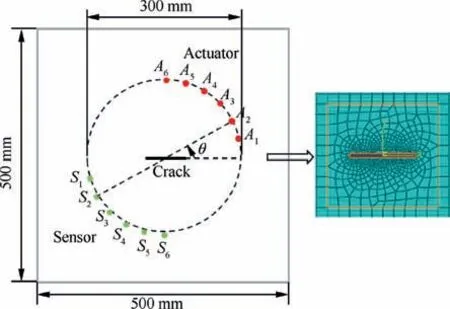
Fig. 1 Dimensions of plate structure, crack location, and mesh around crack used in a 3D FEM analysis.
In general, there are two methods to simulate Lamb wave data. In the first method, both the PZT transducers and the host structure (the plate) are modeled and a perfect bonding between them is assumed. For actuation a voltage input of tone burst signal is applied to the top surface of the PZT sensor. For signal receiving the equipotential condition of the electrode surface of the sensor is imposed by coupling the electric potential degrees of freedom (DOFs) of the surface. For the second method, a vertical force or a uniform in-plane radial concentrated force on the circumferential nodes of sensors is used to represent the input signal31–33. Although both methods have been proven to be consistent with experimental results,the second method has been reported to be more computationally efficient as it does not require the coupling effect between the PZT transducer and the structure34.Therefore,the second method is employed to simulate Lamb wave signal in this study.
Lamb wave is dispersive in nature,and its velocity depends on not only material properties, but also excitation frequencies.In theory there are infinite number of modes with increasing frequencies, which significantly increases the difficulties of signal interpretation. According to the dispersion curve of Lamb wave propagating in a 2024-T3 aluminum alloy plate with 2 mm thickness, the excited Lamb waves have only basic symmetric S0 mode and antisymmetric A0 mode when the product of frequency and thickness is less than 2 MHz·mm.Existing literatures have shown that S0 mode is more sensitive to cracks in metal structures, while A0 mode is more sensitive to impact damage, composite delamination and corrosion damage etc.35. Therefore, the S0 mode is chosen for crack quantification in this study.The excitation frequency of Lamb wave is set to be 0.16 MHz given that the thickness of the target plate is 2 mm in this study.As shown in Fig.2,a Hanningwindowed 3.5 cycles sinusoidal tone burst is used as the excitation signal.
A proper element size is determined as follows. Using the maximum frequency of 160 kHz and the transverse and longitudinal speeds, the minimum wavelength is36–37
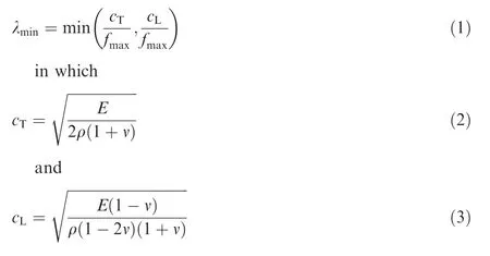
The term λminis the minimum wavelength,cTand cLare the transverse and longitudinal wave velocities, respectively.Terms E, υ, ρ are Young’s modulus, Poisson’s ratio, and the material density, respectively. The terms of cTand cLgiven by Eqs. (2) and (3) are calculated as 3120.3 m/s and 6194.6 m/s, respectively. The minimum wavelength λminis obtained as 19.5 mm. The spatial discretization should meet the condition that at least 10 elements are needed for the minimum wavelength; therefore, the element edge length (Δx) is chosen as 1 mm on average for the mesh generation. Two layers of elements are modelled through the thickness (2 mm). It is worth mentioning that finer meshes should be adopted for damage cases in order to model the crack and wave interaction more reliably. To achieve that, the mesh in the vicinity of the crack is adaptively generated in the FEM package to ensure the interaction between the wave and the crack can be well captured in numerical simulation. For transient analysis the accuracy of the FEM can be improved by setting smaller time steps38. In general, the minimal time step δtneeds to satisfy Eq. (4)
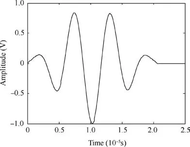
Fig. 2 3.5-cycle excitation signal for Lamb wave.

Table 1 Mechanical properties of specimens.

which ensures that during one time step the propagation length of the wave is less than the size of a discrete element.Therefore, in the numerical analysis, the minimum time step δtis set as 0.1 μs.
2.2. Feature extraction of Lamb wave
Existing studies have shown that each target may have unique local geometries, fatigue crack morphologies, sensor variabilities,and boundary conditions due to manufacture and loading variability. It has been shown in Refs.9,39that a single feature is not sufficient for damage size quantification due to the fact that a considerable variability was observed in the response from different specimens. For a notch-type damage such as a through-thickness crack where there is no contact between two crack surfaces, the transmitted waves are the scattered waves in a detour route from the crack tip27.There is also signal amplitude loss of the transmitted signal due to the reflection wave. The underlying mechanism can be explained as follows. When Lamb waves pass through a crack or a discontinuous area,the transmitted waves are changed because of the forward scattering40–41. The wave amplitude represents the energy of the Lamb waves carried by the signal. The energy of the received signal will reduce if the crack size increases in the pitch-catch method. Another feature is the phase change of the signal, which refers to the difference of the time-offlight between baseline signal and damaged signal. The forward scattered wave will take a detour to the sensors once it encounters a crack. Thus, the time of arrival of the received signal will delay with the crack size increasing27. Based on above discussed mechanisms, the two features (normalized amplitude and the phase change) are employed to estimate crack size through a physical model.
2.3. Results and preliminary discussion
To extract the two features discussed above from simulation signal data, an appropriate time window should be chosen according to the group velocity.The group velocity of the generated Lamb wave at a particular frequency can be verified in an undamaged specimen by measuring the time-of-flight(ToF)between two sensors with a known separation distance.In this study, the group velocity at the frequency of 0.16 MHz is experimentally measured as 5454 m/s. The approximate ToF which represents the first wave package received by the receiver can be obtained according to the distance between the actuator and receiver. The normalized amplitude received at S6with cracks length a ranging from 2 mm to 30 mm and incident angle of 90° are shown in Fig. 3 for illustration. It can be observed that the peak value of normalized amplitude decreases and the phase delays as the length of crack increases.This is consistent with the mechanism discussed above. The results indicate the two damage sensitive features,i.e.,the normalized amplitude and phase change, are reasonable candidates for damage quantification.
Lamb wave signals of all six sensors with different incident angles θ(shown in Fig.1)and a crack length of 15 mm are generated and presented in Fig.4.For obliquely incident wave the wave front does not reach the crack simultaneously across the length, and this alters the wave characteristics. It is observed that the normalized amplitude decreases as the incident angle increases, while the phase change shows an opposite trend.
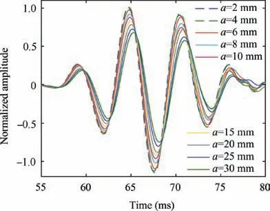
Fig. 3 FEM simulation data of Lamb wave responses for different sizes of cracks with an incident angle of 90°.
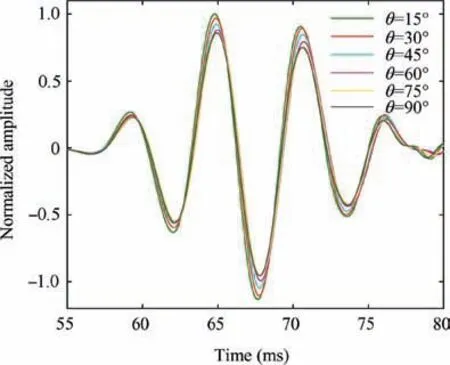
Fig. 4 FEM simulation data of Lamb wave responses with different incident angle for 15 mm crack.
The influence of incident angle on features of Lamb wave based on FEM results are presented in Fig. 5. It can be observed from Fig. 5(a) that the normalized amplitude decreases sharply when the incident angle increases from 15°to 45°, the trend has gradually flattened toward the incident angle of 90°. Whereas the phase change exhibits the opposite trend in Fig. 5(b). It can be seen from Fig. 5(a) and (b) that the changes of the two features (normalized amplitude and phase change) are not obvious when the incident angle is less than about 15°.The values of normalized amplitude with small incident angles are close to 1, indicating that the amplitude of the received signal of a cracked specimen is very close to that of a healthy structure. The values of the phase change with small incident angles are close to 0, meaning that the phase change for a cracked specimen is very similar to that of a healthy structure.This phenomenon indicates that the damage features become less sensitive to small incident angles. As the incident angle increases, the influence of crack on Lamb wave features (normalized amplitude and phase change) becomes more significant.
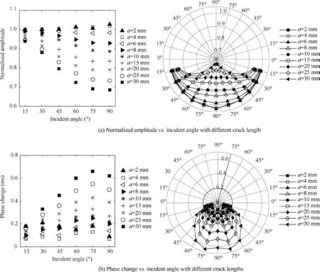
Fig. 5 Influence of incident angle on features of Lamb wave based on FEM results.
It can also be observed from Fig. 5 that, the length of the crack also has a significant impact on Lamb wave features.It shows in Fig. 5(a) and (b) that the features (normalized amplitude and phase change) do not yield significant differences for cracks with lengths smaller than 6 mm, and the results of crack size less than 6 mm are not included in the following discussion. In addition, the minimum detectable crack size varies with different application scenarios and is beyond the scope of this paper.considering the crack orientation for pitch-catch configuration is proposed.The new model is based on the hypothesis that the influence of crack orientation on the damage sensitive features can be represented by an equivalent crack and the angle of incidence, as shown in Fig. 6. The equivalent crack size is defined as the projected length of the inclined crack on the plane which is perpendicular to the path between the actuator and the receiver.
2.4. Model hypothesis of inclined crack
Intensive studies have been reported to study the correlation between the Lamb wave signal and the size of damages23,28,42.A notch or preset crack is usually introduced before fatigue testing in order to obtain an ideal straight crack along the horizontal direction in most of work9,23. However, the crack may not propagate as expected in natural fatigue scenarios. Lu et al.27studied the effect of incident angle on normalized amplitude and found that the normalized amplitude has a monotonic trend with the incident angle in terms of pitchcatch method. Zhou et al.28studied the influence of damage orientation on the intensity of wave energy for pulse-echo method. Santhanam and Demirli43investigated the signal features of obliquely incident Lamb wave at the edge of a plate.Energy reflection coefficients are calculated for the reflected wave modes as a function of the incident angle and the frequency. In this paper, a novel crack prediction model
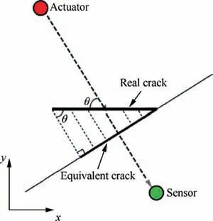
Fig. 6 Schematic representation of geometry relationship between the real crack and the equivalent crack.
The hypothesis yields the following equation according to the geometry shown in Fig. 6.
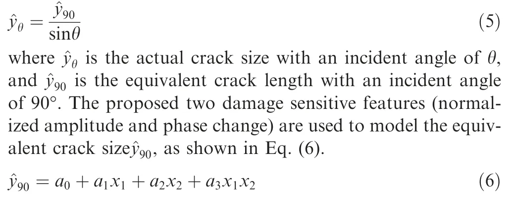
where x1is the normalized amplitude, x2is the phase change,and a0, a1, a2, a3are model parameters which can estimated using simulation data or field data.
2.5. Model verification
Numerical experimental data from FEM are used to verify the effectiveness of the proposed size quantification model.Results associated with the incident angle of 90° with crack lengths ranging from 6 mm to 30 mm are used to estimate the model parameters in Eq. (6)using the Bayesian estimator. The Bayesian posterior of the joint PDF of the model parameters reads,

where y90is the actual crack size, ^y90is the model quantification size given the corresponding x1and x2and a set of model parameters (a0, a1, a2, a3), and the term D denotes the observation data shown in Table 2. Note the total uncertainparameters include the term σ. The second term of the right hand side of Eq.(7)is the Gaussian likelihood with a standard deviation of σ,and first term is the noninformative prior of σ.The Markov Chain Monte Carlo (MCMC) method is employed to draw samples from the posterior joint probability density function (PDF) of the model parameters.
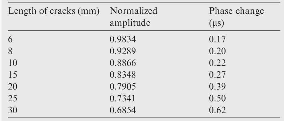
Table 2 Numerical simulation data of two features for case with an incident angle of 90°.
A total number of 107samples are obtained, and the histograms of model parameters are presented in Fig. 7.
Using the mean of the MCMC samples, the deterministic crack size quantification model for inclined crack is

The numerical results of inclined cracks(incident angle varies from 15° to 75°) are used to verify the effectiveness of the model using Eq. (8). Fig. 8 presents the model prediction of the crack sizes vs. the actual crack sizes for inclined cracks.It can be observed that, for cases where the incident angles are larger than 30°, the model prediction results are within 99% confidence interval; however, most of prediction results are outside the 99% confidence interval for the case with the incident angle of 15°. The results indicate that discontinuities or damages have trivial effect on Lamb wave when the propagation path of the wave is approximately parallel with the damage direction. Nevertheless, the damage may still alter the wave when the size of the damage is large enough. It is shown in Fig.8 that the prediction results gradually merge into the 99% confidence interval when the crack size is larger than 20 mm for the 15° case.
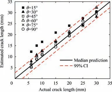
Fig. 8 Model predicted crack lengths vs. actual crack lengths under different incident angles.

Fig. 7 Histograms of model parameters by MCMC.
3. Experimental validation
To validate the overall proposed method, aluminum plates with different crack sizes are used as representative plate-like structures, and an array of PZT sensors are installed around the crack to obtain the Lamb wave data from different incident angles.The one set of testing data are used to obtain the model parameters and the rest of the data are used for validation.The details are presented below.
3.1. Experimental design
Lamb wave testing on aluminum plates with through-thickness cracks of different sizes and incident angles is performed using surface-bonded piezoelectric wafers. The actual plate specimens have the same dimensions (shown in Fig. 1) and the mechanical properties (shown in Table 1) as the plate used in FEM numerical experiments. A 0.4 mm-width throughthickness crack is manufactured using the method of electric discharge machining (EDM) in the middle of the plate. The length of through-thickness cracks varies from 6 mm to 10 mm with an increment of 2 mm, and from 10 mm to 30 mm with an increment of 5 mm. The experimental setup is presented in Fig.9.A multi-channel PZT array scanning system is used to generate and acquire Lamb wave data44. An array of PZT sensors shown in Fig. 9 are installed as a pitch-catch configuration. Actuators with incident angle (θ)of 15°, 30°, 45°, 60°, 75°, 90° are used to generate Lamb wave signal in sequence. A 5-cycle Hanning-windowed tone burst with a central frequency of 160 kHz is used as the excitation signal.For each of the angles,the corresponding actuator generates Lamb wave signals and the sensor in the opposite location acquires the Lamb waves passing through the damage area. The sampling frequency of the sensor is 10 MHz and a total length of 5000 sample points are recorded.
3.2. Signal processing and features extraction
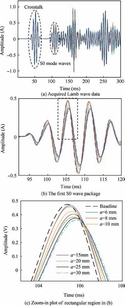
Fig. 10 Lamb wave data obtained by A4-S4 path.
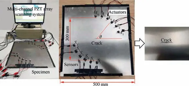
Fig. 9 Experimental setup and a specimen with 12 PZT sensors in a pitch-catch configuration.
In addition to the damage cases, the Lamb wave data for an intact plate are collected and used as baseline (healthy) signal.The Lamb wave data acquisition is performed twice for each combination of the crack size and the incident angle to minimize the acquisition process uncertainty. One example of the actual Lamb wave data acquired by the A4-S4path(PZT labels shown in Fig.9)is shown in Fig.10.The first received S0 wave package is shown in Fig.10(b),and a subset of the signal data in the dash rectangle in Fig. 10(b) is enlarged and shown in Fig. 10(c). It can be seen from Fig. 10(c) that the amplitude reduces as the crack size increases and the phase change (in terms of time delay of the peak of the wave form) also increases as the crack size increases.
The normalized amplitude and the phase change are extracted from the experimental data. The results of normalized amplitude and phase change vs. incident angle are presented in Fig. 11(a) and (b), respectively. Results indicate that both the normalized amplitude and the phase change exhibit a monotonic trend, which agrees with the previously discussed mechanisms and numerical experiments. It should be noticed that both features for cases with small incident angles(15° and 30° cases) are almost unchanged compared with the two features with the healthy case.This phenomenon also indicates that the damage or discontinuities have a light influence on the Lamb wave characteristics when the incident angle is relatively small. Therefore, the damage quantification using Lamb wave for cracks with small incident angles in the pitch-catch configuration may yield unreliable results. The detailed results of experiment at the incident angle of 90°degrees are shown in Table 3.
3.3. Results and discussion
Using the proposed two-feature crack size quantification model in Eq. (6), model parameters are estimated using the Bayesian estimator. The Bayesian posterior in Eq. (7) is used with experimental data obtained from all crack lengths with an incident angle of 90° shown in Table 3. A total number of 107samples are drawn using MCMC simulations. Based on the MCMC samples,the resulting mean model for inclined cracks is

Fig. 12 presents the performance of model prediction evaluated at all the combinations of crack lengths and incident angles. It can be seen that most of the actual crack lengths are within the 99%confidence interval of the model prediction.
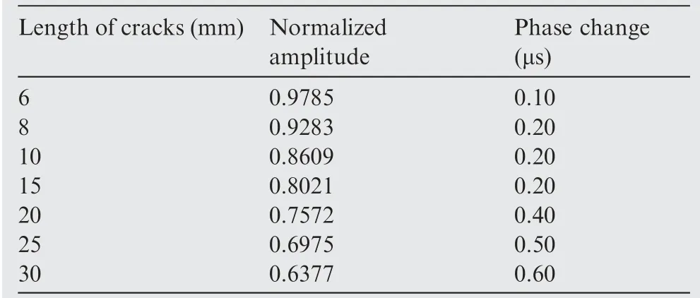
Table 3 Experimental data of the two features for the case with an incident angle of 90°.
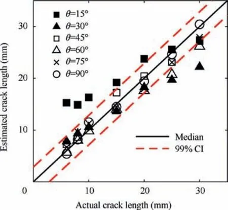
Fig. 12 Comparisons of model prediction and actual crack size for different incident angles and crack sizes.
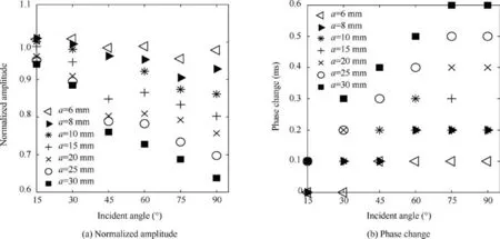
Fig. 11 Influence of incident angle on damage sensitive features of Lamb wave based on experimental results.
It can also be observed from Fig. 12 that the predicted crack sizes for cases with incident angles of 15° and 30° are not always within the 99%confidence interval.It indicates that the model may not give reliable results when the incident angle is relatively small. The average error given in Eq. (10) can be used as a quantitative measure for the prediction performance

It is noticed that the model parameters obtained from FEM numerical experiments (in Eq. (8)) and actual experiments (in Eq.(9))are different.Although the geometry and the material properties of the FEM and the actual experiment are identical,the difference may be caused by uncertainties between the ideal finite element simulation and the actual field data.Yang et al.39proposed a probabilistic crack size quantification method based on Bayesian updating.It combines the simulation results and the experimental data to achieve more accurate crack size predictions. As mentioned in the previous numerical experimental analysis, both the angle and the crack size can affect the prediction performance. The average error only provides a deterministic and simple criterion for the angle beyond which the proposed method can achieve reliable quantification results. The factor of the crack length is not included. Next,to fully investigate the performance of the proposed model subject to both factors, a probabilistic measure is proposed to provide a more rational evaluation for the prediction performance.
4. Probability of reliable sizing for inclined cracks
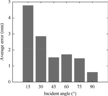
Fig. 13 Average errors at different incident angles.
The process of non-destructive evaluation generally involves various uncertainties due to sensor installation, mechanism modeling, data acquisitions, and so on. The uncertainties are handled through the probabilistic parameter estimation process mentioned previously.The average error is a conventional tool to signify the mean difference between the predicted size and the actual size, and is unable to account for the uncertainty. To evaluate the performance of the model in a more rational manner, a probabilistic measure, namely, the probability of reliable quantification (PRQ), is proposed. A reliable sizing bound is defined using the α-confidence interval of the mean prediction as shown in Fig. 14 where a 99% confidence interval of the mean are used for illustration. The PRQ is defined as the probability of the model prediction being within the α-confidence interval, as identified in the shaded region in Fig. 14. Mathematically, the PRQ can be expressed as

Model parameters in Eq. (6) are estimated using both experimental and FEM data associated with the cases having an incident angle of 90°. Using the Bayesian estimator with MCMC simulations, a total of 107samples of the model parameters are obtained.For each of the samples,a realization of the crack sizes using the signal features can be obtained.After that, the histograms of the predicted crack sizes are obtained to compute the PRQs using Eq.(11). Results of PRQ for all the combinations of angles and crack sizes are shown in Table 4. It is observed that for cases where θ ≥45°the model can yield reliable predictions of the crack size. For cases where the angles are smaller than 45° the results are not consistently reliable. One possible explanation is that the cracks in these cases become more and more parallel with respect to the wave propagation path,making the two features less sensitive to the cracks.
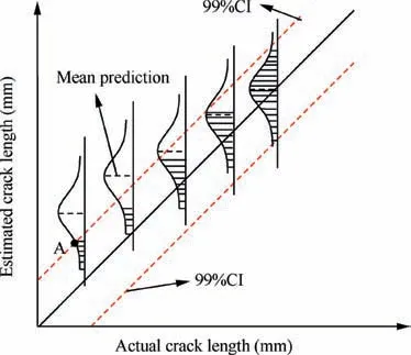
Fig. 14 Concept illustration of proposed probability of reliable quantification (PRQ).
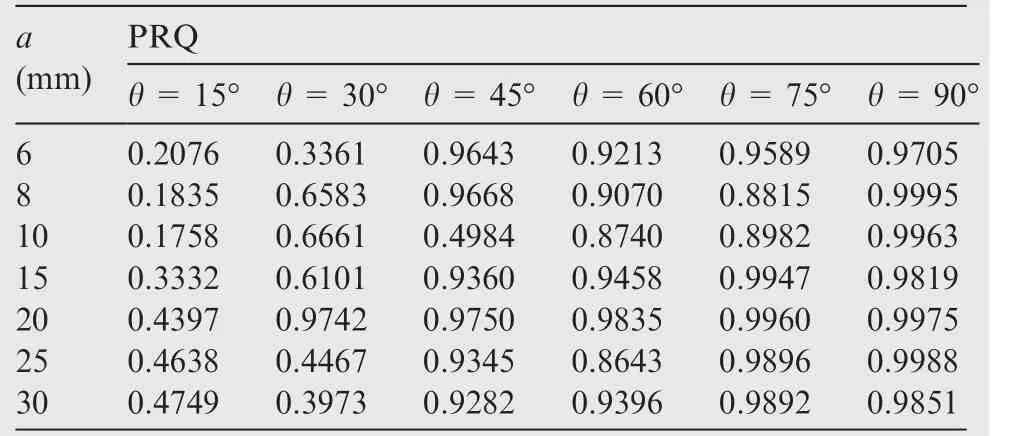
Table 4 Performance of model prediction in terms of PRQs under different crack sizes and incident angles.
5. Conclusion
This study developed a quantification model for inclined cracks using Lamb wave in plate structures. The effect of the crack orientation to Lamb wave signal features was investigated using numerical experiments based on FEM. Two damage sensitive features, namely the normalized amplitude and the phase change,of the first wave package of Lamb wave data were used to characterize the crack size. To include the effect of crack orientation to the size quantification, a hypothesis based on the geometrical influence of the inclined crack on the two features was proposed. Based on this hypothesis, the crack size quantification model incorporating the inclined angle of the crack was developed. The effectiveness of the model was verified using numerical experimental data.To validate the hypothesis and the model, experimental data were obtained using aluminum plates and piezoelectric (PZT)wafer-type sensors around through-thickness cracks with different lengths. The performance of model prediction is evaluated in terms of average errors. Results indicated that the proposed model can yield reliable results for inclined cracks when the inclined angle is not less than 30°. To fully evaluate the performance considering the angle and the crack size, a probabilistic measure is proposed. Based on the current results, the following conclusions were drawn.
1. The effect of the crack orientation on the signal features of Lamb wave is significant, and the affected signal features can be used to model the inclined crack size.
2. The proposed hypothesis based on the geometrical influence on the signal features provides a viable interpretation for the crack orientation effects.The resulting size quantification model is verified using numerical experimental data and validated using realistic experimental data.
3. An index of probability of reliable quantification is proposed to evaluate the performance of the crack size quantification model. The index can give an overview of the ranges of crack angles and crack sizes in which the model performs relatively accurate. The index can be used to determine the boundary where the sizing risk is given in terms of probabilities. Using this probabilistic measure,the prediction results for cracks with incident angles of 15° and 30° show a larger deviation from the actual sizes.
It should be noted that only one fitting model is used to fit the crack size with an incident angle of 90°. In fact, it is considered that any model can be applied here, because the angle works on the whole model and does not work on one of the parameters in the model. However, the differences between the models are not described in this study,which needs further study. In addition, the current study focuses on the effect of the crack orientation, and future work is needed to address how to quantify the crack size when the incident angle is not known a priori. Besides this, more complicated cases where the incident angle of Lamb wave changes with respect to loading direction in a real structural testing setting will be studied.And the scope of the model can be extended to composite materials.
Acknowledgements
The research reported in this paper was supported by Science Challenge Project of China (No. TZ2018007) and National Natural Science Foundation of China (Nos. 11872088 and 51975546).
 CHINESE JOURNAL OF AERONAUTICS2021年2期
- CHINESE JOURNAL OF AERONAUTICS的其它文章
- Recent active thermal management technologies for the development of energy-optimized aerospace vehicles in China
- Electrochemical machining of complex components of aero-engines: Developments, trends, and technological advances
- Recent progress of residual stress measurement methods: A review
- Micromanufacturing technologies of compact heat exchangers for hypersonic precooled airbreathing propulsion: A review
- Towards intelligent design optimization: Progress and challenge of design optimization theories and technologies for plastic forming
- A combined technique of Kalman filter, artificial neural network and fuzzy logic for gas turbines and signal fault isolation
