An intelligent target detection method of UAV swarms based on improved KM algorithm
Xiangming ZHENG, Chunyao MA
Key Laboratory of Fundamental Science for National Defense Design Technology of Flight Vehicle, Nanjing University of Aeronautics and Astronautics, Nanjing 210016, China
KEYWORDS 3D probability map;Kuhn-Munkres algorithm;Path planning;Real-time control;Swarm intelligence;Target detection;Unmanned aerial vehicle(UAV)
Abstract Complete and efficient detection of unknown targets is the most popular application of UAV swarms. Under most situations, targets have directional characteristics so that they can only be successfully detected within specific angles.In such cases,how to coordinate UAVs and allocate optimal paths for them to efficiently detect all the targets is the primary issue to be solved. In this paper, an intelligent target detection method is proposed for UAV swarms to achieve real-time detection requirements. First, a target-feature-information-based disintegration method is built up to divide the search space into a set of cubes. Theoretically, when the cubes are traversed, all the targets can be detected. Then, a Kuhn-Munkres (KM)-algorithm-based path planning method is proposed for UAVs to traverse the cubes.Finally,to further improve search efficiency,a 3D realtime probability map is established over the search space which estimates the possibility of detecting new targets at each point. This map is adopted to modify the weights in KM algorithm, thereby optimizing the UAVs’ paths during the search process. Simulation results show that with the proposed method, all targets, with detection angle limitations, can be found by UAVs. Moreover, by implementing the 3D probability map, the search efficiency is improved by 23.4%–78.1%.
1. Introduction
Searching for a set of unknown targets in an area with the highest efficiency is the most common application of UAV swarms,1,2and it is the basis for UAV swarms to realize more complex combat missions. In recent years, significant research efforts have been invested in developing intelligent collaborative search methods for UAV swarms.3–5A very large part of these research assume that the targets can be detected in any direction.However,this is not usually the case.For example, in vision-based detection, the characteristic features of a target can only be recognized effectively within a certain angular range.6,7Similarly,IAI Harpy can only detect a radar when it is within range of the radar’s transmitting angle.8Under such situations, the difficulty of detection increases dramatically. And yet there are sparse researches focusing on the detection of such targets,i.e.,the detection of a set of unknown targets while a target can only be successfully detected from specific angles.
At present, the mainstream research of target detection relies on decomposing the target area into grids to be individually visited by UAVs.9,10In Ref.11, the search space was partitioned into a collection of identically sized grid cells and a sequence of grid cells were selected for each UAV as the search path. In Ref.12, distributions of targets are discretized into a grid and a Gaussian mixture model was used as guidance to search for effective paths consisting of grid cells. Such gridbased search strategies are mainly divided into probabilitydriven search13,14and coverage path planning based search.15
Probability-driven search contributes to global optimization problems whose objective functions are non-convex,non-differentiable and may not be contiguous. Therefore,probability-driven search strategies, such as evolutionary programming, particle swarm optimization and ant colony optimization, are widely used in target search missions of UAV swarms under indeterministic search scenarios, whose objective functions are difficult to formulate.
In Ref.13,the author proposed a swarming search strategy,which is a decentralized method based on pheromone maps.Under the guidance of the gradient of the pheromone map,each UAV in the swarm generates simple reactive behaviors to achieve coordinated exhaustive searches. In Ref.14, the author integrated adaptive strategy and chaotic optimization search theory into the standard PSO algorithm. There are two main improvements to the standard PSO algorithm: (A)adaptively adjusting the weights of the PSO parameters (inertia,local best,and global best)to improve the search ability of the algorithm;(B)applying chaotic optimization search mechanism to improve the ability of avoiding local optimal.Another ant Colony Optimization (ACO) based search method, for determining the trajectories for a UAV swarm which is looking for lost targets in the shortest possible time,was proposed in Ref.16.The scenario was discretized and modelled as a graph which is considered as a probability map being updated with information obtained from the UAV sensors.The attraction of each cell is based on the location and the possible actions of the UAVs with respect to the probability information of the target location. A PSO-based algorithm, which can generate search trajectories for a UAV swarm in a disaster scenario, was proposed in Ref.17. The authors achieved the objective of enabling UAVs to search and aggregate towards several victim groups.
The above researches, which are based on search probability,are incremental processes whose next-step strategy depends on the results of previous steps. It is suitable for search problems that cannot be formulated and optimized with a simple objective function at the beginning of the mission, which is usually the case in an unknown search environment.18However, the probability-driven search is basically a stochastic search method, and therefore it is difficult to guarantee the complete detection of all targets.
To achieve coverage search, which is integral to the complete detection of all unknown targets in a certain area, many coverage path planning search strategies have been developed.19Coverage path planning based strategies mainly consider the target search problems as finding a set of routes which must fulfil all the detection requirements, satisfy the operational constraints and minimize the objective function that reflects the cost of search.20The search problem is usually carried out by constructing a graph,so that when all nodes or edges are accessed by UAVs, the search is completed.
In Ref.21, the authors considered a multi-UAV path planning problem with loitering and timing constraints.With their model, scenarios where waypoints must be accessed at least once under a given time constraint can be formulated.Instead of covering graph nodes, the problem of boundary coverage,whose objective is to generate coordinated reconnaissance paths that cover a set of graph edges, was addressed in Ref.22.The work in Ref.23focused on the problem of generating paths for multiple UAVs with the objective of maximizing the amount of information that can be collected from the desired area. Information is obtained by downward facing cameras mounted on the UAVs.In Ref.24,the authors focused on the dynamic routing problem with the objective of spatial and temporal coverage of a set of waypoints which are modelled as nodes in a graph. The spatial coverage is achieved by traversing the waypoints distributed over the area.The temporal coverage is related with the time constraints which determine when the waypoints have to be visited. The objective in Ref.25is to minimize the longest tour performed by each UAV,which is equivalent to minimizing the total mission time.In Ref.26, the authors proposed an algorithm exploring optimal and collision-free paths in 3D space to completely cover the area of interest.
The coverage path planning based strategy formulates the search mission into an optimal path planning problem, e.g.,Multiple Traveling Salesman Problem (MTSP). The search objective is achieved by exhaustively traversing waypoints.Therefore,it has some deficiencies in search efficiency.In addition, the above research carries out the search exercise mainly based on the relative spatial relationship between UAVs and targets in the search area,without considering the characteristics of the targets.Putting it another way,they all assume that the targets can be detected in any direction. However, under most situations,such as vision-based search where the characteristic features of a target can only be recognized effectively within a certain angular range, the above methods will not apply.
This paper focuses on the efficient and complete detection of targets which can only be detected within specific angles,e.g., the detection of ground-based radars. First, based on the range of the angle within which a target can be successfully detected,we come up with a method to disintegrate the search space into a set of cubes. Then the center-points of the cubes,i.e., Reconnaissance Points (RPs), are allocated to UAVs as their Potential Waypoints(PWs)guiding their flight directions.During the real-time search process, the RPs are dynamically assigned to UAVs using Kuhn-Munkres (KM) algorithm27according their distances to the UAVs.Note that it is not necessary for a UAV to reach its assigned PWs, and the PWs assigned to a UAV are likely to be different at each moment.By traversing the RPs, all the targets can be detected despite of their various constraints on detection angles. In order to further improve the search efficiency, based on the position information gathered from the detected targets, we establish a real-time 3D probability map, on which the value of each point describes the estimated possibility of detecting new targets when a UAV is at this point. This map is used to modify the weights in KM algorithm when allocating RPs to UAV swarms, whereby the paths of UAV swarms can be optimized in real time and the detection can be implemented more efficiently.
The contributions of this paper can be summarized as:
(1) We have introduced a target-feature-information-based search space disintegration method which divides the search space into a set of cubes. Theoretically, when the cubes are traversed, all the targets, which can only be found in specific angles, can be detected.
(2) We have developed a real-time path planning method for the UAV swarm to traverse the search space, in the way that minimizes the flight cost such as the total distance of flight of the UAV swarm, based on the real-time detection results.
(3) To further improve search efficiency, we have introduced a real-time 3D probability map over the search space which can be used to improve the path planning process and guide the UAV swarm to the area with higher target detection probability.
Simulation results show that with the proposed method,all targets, with detection range limitations, can be found by UAVs. Moreover, by implementing the 3D probability map,the search efficiency is improved by 23.4%–78.1%. The remainder of this paper is organized as follows. Section 2 introduces our studied problem. Section 3 delineates in detail the proposed method for searching targets with detection direction limitations. Section 4 demonstrates the experimental study with different target models and discusses the simulation results. Section 5 concludes the paper.
2. Problem description and modelling
2.1. Problem description
In this paper,we focus on the problem of searching a set of static targets with a UAV swarm.Considering the reality of most target detection problems,we assume that a target can only be successfully detected at specific angles, while a UAV can only perceive the existence of targets within a certain distance in its vicinity. The UAV swarm adopts centralized or distributed control strategies which can make real-time mission planning for each UAV and information can be shared among UAVs in the swarm.
2.2.2. Target set modelling
The set of targets to be detected are represented by a sequence:T={T1,T2,···,TNT}. NTis the total number of targets to detect.Since a target can only be successfully detected at specific angles,we model the range of the angles using a conical area radiated from the target,as shown in Fig.2.The jthtarget Tjin the sequence is therefore represented as: Tj=(xTj,yTj,zTj,φTj,θTj,γTj,STTj). xTj,yTj,zTjare the Cartesian coordinates of the position of target Tj, while φTj,θTj,γTjmodel the conical area within which Tjcan be detected.φTjand θTjdescribe the direction of the conic region.We denote the central axis of the conic region as Aj, φTjand θTjrepresent the angle between Ajand z axis, xaxis respectively. γTjis the vertex angle of the conic region. STTjrepresents the status of target Tj, with STTj=0 if target Tjis not detected yet and STTj=1 if target Tjis detected. Before Tjbeing detected, its position and detection angle parameters are unknown to the UAV swarm.
2.2.3. UAV swarm modelling
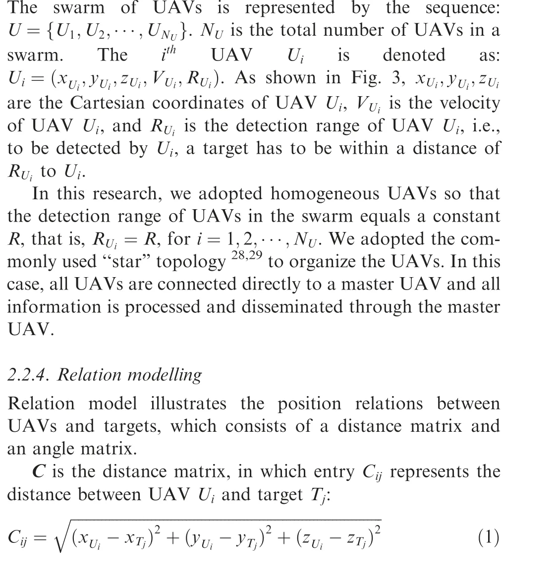
2.2. Scenario modelling
This search scenario can be modelled as a composition of a search space model, a UAV swarm model, a target set model,a relation model between the UAV swarm and the targets set,and the detection conditions. The scenario is shown in Fig. 1.
2.2.1. Search space modelling
The search space is modelled as a cuboid area (A,B,C)∈R3,whose length, width and height are A, B and C respectively.Targets with fixed positions are distributed in an unknown manner on the ground. UAVs fly in G to detect the set of targets.
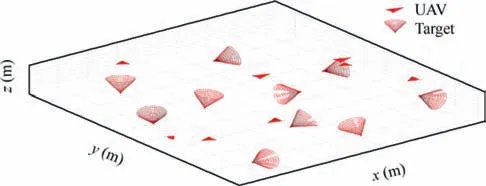
Fig. 1 Schematic diagram of search scenario.
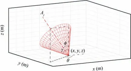
Fig. 2 Model of target Tj.
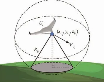
Fig. 3 Model of UAV Ui.
δ is an angle matrix.We denote the segment which connects UAV Uiand target Tjas lij, then entry δijin δ represents the angle between lijand Aj,which describes the deviation of UAV Uifrom the center of the area where target Tjcan be detected.
2.2.5. Detection conditions
To detect target Tjwith UAV Ui, there are two conditions to be met. First, the distance from Tjto Uicannot exceed the detection range R of Ui, that is,

Second,Uimust be within the conic region in which Tjcan be detected, which can be described as

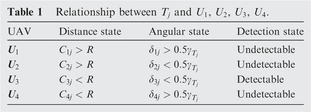
This means that δij,the angular deviation of UAV Uifrom the center-line of the conic region, must not exceed 0.5γTj, the angle between the generatrix and the center-line of the conic region. Thus the area where a UAV can detect Tjcan be represented by the spherical sector Xj(Tj,R,γTj,Aj) shown in Fig.4,located at the position of target Tj.The detection range R of UAVs is the radius of the sphere sector, while γTjis the vertex angle. UAV U1, U2and U4are all outside the spherical sector,and therefore they are not able to detect target Tj.Only UAV U3is located inside the spherical sector and can detect target Tj. The relationship between Tjand U1, U2, U3, U4in Fig. 4 can be illustrated by Table 1.
3. Methodology
3.1. Methodology overview
As described in Section 2,we aim to detect a set of ground targets, with directional characteristics, using a UAV swarm.There are many factors that affect the efficiency of UAV swarm to perform detection tasks, such as the number of UAVs, the entry direction to the task area, the disintegration density of search space and real-time path planning.Generally speaking, the number of UAVs only has a qualitative impact on the detection efficiency because a larger UAV swarm can do a coverage search with less time cost.30,31Therefore,in this paper, we mainly investigate how the same size UAV swarm can complete the detection task in a shorter time. Similarly,the entry direction of UAV is affected by the relative position between UAV bases and the detection area. It will not be an element to be optimized in this paper.
Considering that if the search space disintegration density and the path of UAVs are optimized and updated in real time during the detection process, the complexity of the optimization will be very high. It will be difficult to find a satisfactory solution within reasonable time and be implemented in realtime detection which is an incremental process whose nextstep strategy depends on the results of previous steps. Therefore, we propose an algorithm which generally encompasses 2 steps:(A)search space disintegration based on target characteristics at the beginning of the detection and (B) real-time search path planning for the UAV swarm based on the current detection results.
The search space disintegration aims to break down the search space into a set of small cubes. The center-points of the cubes will be assigned to UAVs dynamically as their waypoints during the search. How to determine the size of the cubes to ensure the efficient detection of all targets is the focus of this step.
Visiting the cubes obtained in the first step enables us to detect targets with any distributions in the search space.UAVs should traverse the waypoints in the way that minimize their flight cost such as the total flight distance. We realize this objective by KM algorithm, which will be elaborated later.To further improve the search efficiency under these situations,we build a 3D probability map in the search space to reflect the expected distribution of probability of detecting new targets.The 3D probability is updated based on the position of the new detected targets.We modify the weights of KM algorithm
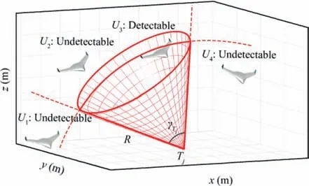
Fig. 4 Schematic diagram of detection requirements.
under the guidance of the 3D probability map. When a waypoint has a larger value on the map, its priority to be visited by UAVs will be improved. Our methodology is depicted in Fig. 5.

Table 1 Relationship between Tj and U1, U2, U3, U4.
3.2. Search space disintegration based on targets detectable features
During the detection process, a set of PW is required to be deployed for the UAV swarm guiding the coverage search of the mission space. The density of these PW will determine the search efficiency and effectiveness. The disintegration in this step is to divide the search space into identical cubes and the center-points of the cubes are set as the PW.Note that the deployment of PW is only to guide the UAV to cover all the cubes so as to cover the search space, and therefore a UAV does not necessarily need to reach its assigned PW.When a UAV passes any point in a cube,the search task in this cube is regarded as completed and the PW inside this cube is marked as visited.Thus,the search efficiency and effectiveness are determined by the size of the cubes. If the cubes are too large, UAVs may fail to detect some of the targets, since the mission field is not able to be totally covered. If the cubes are too small, the detection will consume extra time and resources because many extra waypoints are generated and therefore the mission field is overly visited.In this paper,based on the targets’detectable characteristic,i.e.,γTj,we establish a search space disintegration method that can ensure the detection of all targets while still promising high efficiency.
Since a target Tjhas a spherical sector Xj(Tj,R,γTj,Aj)within which it can be detected, to guarantee its detection,we need to ensure that there is always at least one complete cube inside its spherical sector Xjso that when a UAV enters wherever in this cube, it will be inside the spherical sector and is able to detect the target. Putting it another way, if no complete cubes are inside Xj,even if all cubes are visited there is still a possibility that target Tjis not detected because UAVs may happen to only visit the part of the cubes that is outside Xj.
Our aim is to disintegrate the search space into cubes parallel to x,y,zaxis and to ensure a complete cube inside the spherical sector of each target. One challenge in determining the cube size is the uncertainty of the directions of the conical area of different targets. The direction of the cubes has to be parallel to x,y,z axis while the direction of the spherical sectors of the targets can be various. Note that the biggest inner cube inside a sphere can be placed in any direction inside the sphere. Therefore, by determining the biggest inner sphere of spherical sector Xjand consequently determining the biggest inner cube of the sphere,we can obtain a cube,i.e.,the biggest inner cube,inside Xjwhich can be easily placed in the direction of x,y,z axis. As shown in Fig. 6(a), we denote the biggest inner sphere of the spherical sector Xj(Tj,R,γTj,Aj) as Sj. We denote the biggest inner cube, whose edges are parallel to x axis, y axis and z axis, of sphere Sjas CUj. It can be observed that the size of sphere Sjis constant no matter in what direction Ajis. As a result, the width Ljof CUjis not affected by the change in the direction of Aj.
When the search space is disintegrated into a set of identical cubes, the cubes should be uniformly distributed in the search space. If the size of the cubes Ljc for disintegration is set as Lj,due to different targets positions and different directions of the spherical sectors, when uniformly arranging the cubes, the positions of the cubes in the spherical sectors are likely to be different from the situations shown in Fig. 6(a). They can be totally outside, totally inside or partially inside the spherical sector. Therefore, it cannot be ensured that there is at least one cube totally inside Xjso that Tjis able to be detected.
Note that when Ljc =0.5Lj, there are maximum 4 cubes totally inside Xj, composing CUj. Under this situation, when a cube is partially inside Xj, one of its neighboring cubes can be totally inside Xjregardless of the relative positions inside Xj, as shown in Fig. 6(b). Thus, the maximum dimension of the cubes to ensure the detection of target Tjis 0.5Lj. Therefore the maximum dimension of the cubes to detect all the targets is min{L1c,L2c,···,LNTc }. The disintegrated search space is shown in Fig.7.The search space is disintegrated into a set of identical cubes, which are shown in green. The black asterisks are the center-points of the cubes.
3.3. Real-time path planning method based on KM algorithm
Taking the center-points of the cubes obtained in Section 3.2 as the RPs.The RPs are assigned to UAVs as PW in the search process.Based on the model of the disintegrated search space,we introduce the following notations:

M is defined as an assignment matrix of size NU×ND. If entry Mij=1, Djis assigned to UAV Ui, otherwise Mij=0.

Fig. 5 Methodology overview.
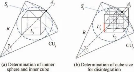
Fig. 6 Calculation of the dimension of cubes for disintegration.
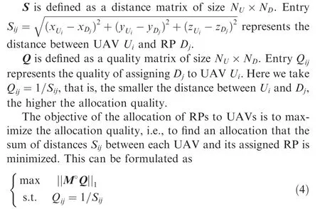
The°in Eq.(4)represents the Hadamard product of matrix M and Q, which produces another matrix of the same dimension as the operands where each element i,j is the product of elements i,j of the two original matrices.
We use KM algorithm to achieve the allocation objective.KM algorithm is a classical optimization algorithm to solve the maximum-weighted matching problem of bipartite graphs.In other words, if the objects in one group are linked to the objects in another group by the weights between them, KM algorithm can pair the objects in the two collections in such a way that the sum of the weight between each pair can be maximized. In our case, putting the distance between a UAV and a RP as the weight, KM algorithm can allocate UAVs to associated RPs so as to minimize the sum of distances and consequently maximize the allocation quality.
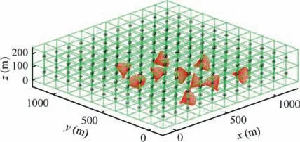
Fig. 7 Disintegrated search space.
KM algorithm aims at complete matching, which requires that the number of individuals in both groups to be equal.However, in our problem, as the reconnaissance process proceeds, the number of remaining RPs, i.e., RPs that are yet to be visited, will continue to decrease. Thus, the number of UAVs and the number of RPs to be allocated will not maintain the same.To obtain equal numbers of UAVs and RPs so as to have two equal-size groups,we add a set of virtual individuals to fill the group which has smaller size. The distances between virtual individuals and the individuals in the other group are set as +∞so that these virtual individuals will not affect the assignment results.
Taking Nm=max{NU,ND},the diagram of RP assignment using KM algorithm is shown in Fig.8.UAVs are assigned to RPs to maximize the sum of Qijbetween the paired Uiand Dj.The detailed procedures of KM algorithm is described in Algorithm 1 and the result of path planning based on KM algorithm at one moment during search process is depicted by Fig. 9. The UAVs are connected to their assigned RPs by the dash lines.It can be observed from Algorithm 1 that the KMalgorithm-based RP assignment process has a polynomial runtime complexity(worst case O(n3)).32AS the number of UAVs and RPs increases,each assignment will take more time which is linear to n3.Therefore,it is more suitable for small-scale onboard execution of target detection to ensure good performance and flight safety of UAVs.
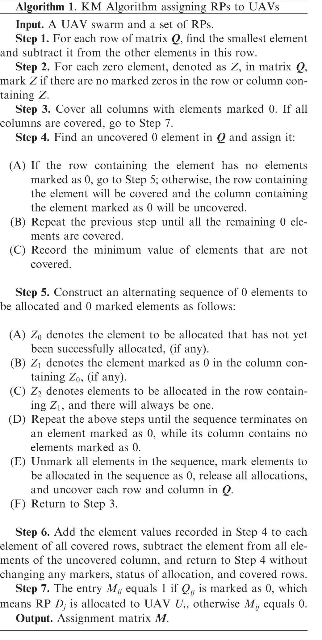
Algorithm 1. KM Algorithm assigning RPs to UAVs Input. A UAV swarm and a set of RPs.Step 1.For each row of matrix Q,find the smallest element and subtract it from the other elements in this row.Step 2. For each zero element, denoted as Z, in matrix Q,mark Z if there are no marked zeros in the row or column containing Z.Step 3. Cover all columns with elements marked 0. If all columns are covered, go to Step 7.Step 4. Find an uncovered 0 element in Q and assign it:(A) If the row containing the element has no elements marked as 0,go to Step 5;otherwise,the row containing the element will be covered and the column containing the element marked as 0 will be uncovered.(B) Repeat the previous step until all the remaining 0 elements are covered.(C) Record the minimum value of elements that are not covered.Step 5. Construct an alternating sequence of 0 elements to be allocated and 0 marked elements as follows:(A) Z0 denotes the element to be allocated that has not yet been successfully allocated, (if any).(B) Z1 denotes the element marked as 0 in the column containing Z0, (if any).(C) Z2 denotes elements to be allocated in the row containing Z1, and there will always be one.(D) Repeat the above steps until the sequence terminates on an element marked as 0, while its column contains no elements marked as 0.(E) Unmark all elements in the sequence, mark elements to be allocated in the sequence as 0, release all allocations,and uncover each row and column in Q.(F) Return to Step 3.Step 6. Add the element values recorded in Step 4 to each element of all covered rows, subtract the element from all elements of the uncovered column, and return to Step 4 without changing any markers, status of allocation, and covered rows.Step 7. The entry Mij equals 1 if Qij is marked as 0, which means RP Dj is allocated to UAV Ui, otherwise Mij equals 0.Output. Assignment matrix M.
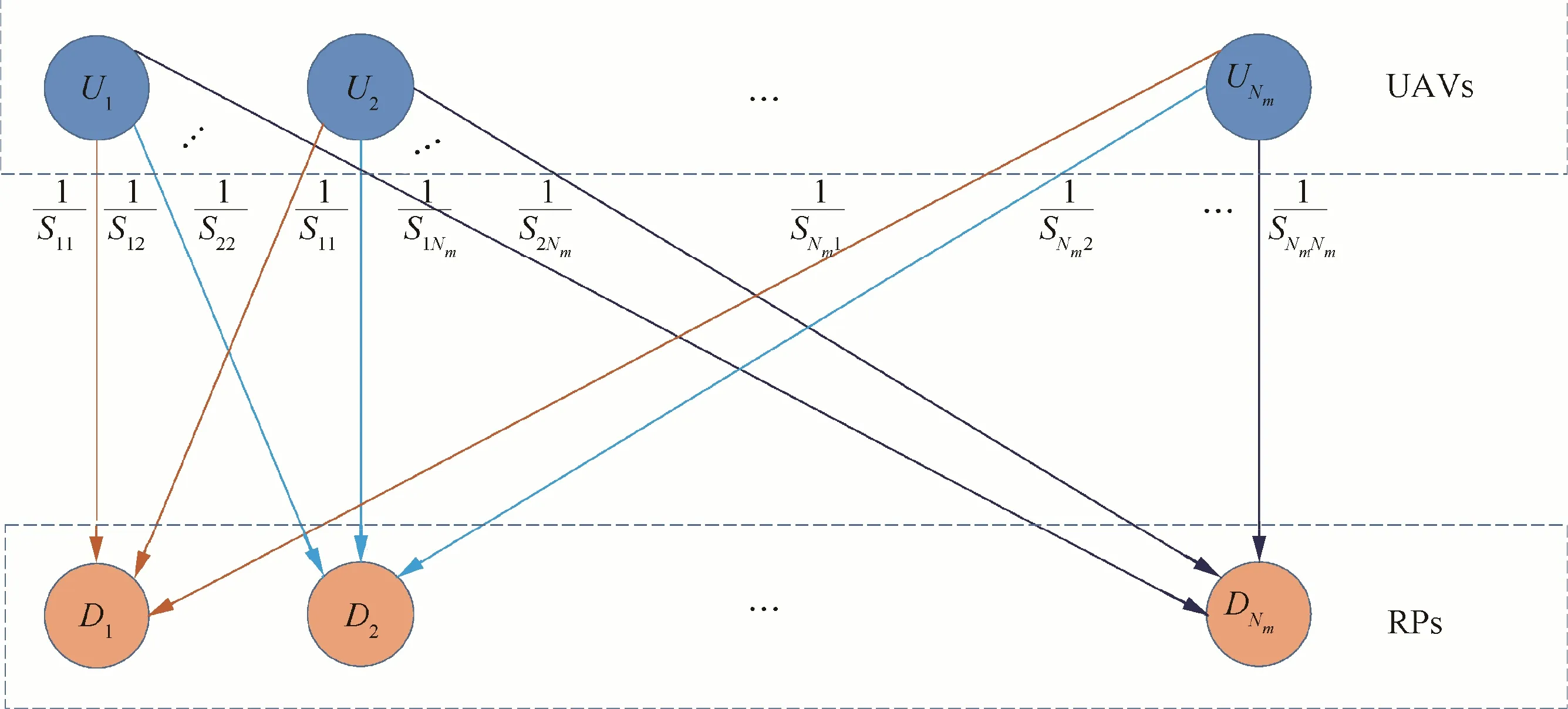
Fig. 8 Schematic diagram of RP assignment using KM algorithm.
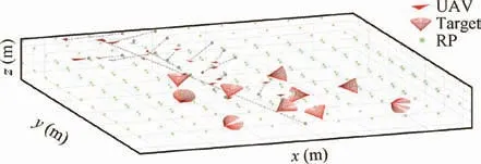
Fig.9 Result of real-time path planning based on KM algorithm at one moment during search process.
3.4. Improved KM algorithm based on real-time 3D probability maps
In Section 3.3,we have introduced the real-time path planning method based on KM algorithm.However,there is a potential that many RPs are visited unnecessarily during the mission.As in most detection tasks,the distribution of targets follows certain rules.One example is the distribution of ground radars.In order to deal with the threat of anti-radar missile and electronic interference, as well as improve the detection accuracy and survivability of radar system, each radar (a target for detection) is separated from each other in space positions.33,34Another instance is that, in the bomb detection task of antiterrorism operations,bombs(targets for detection)are usually arranged separately in a certain rule in the region.
Based on these facts, we can assume that if a target is detected by a UAV, the probability of the existence of other targets in its vicinity will be very low (close to 0). If the UAV swarm continues to visit the RPs around the detected target, it is likely that no new targets can be found, which reduces the search efficiency. To avoid such problems, we introduce a 3D probability map, which can be adopted to modify the weights between UAVs and RPs in KM algorithm and to guide UAVs towards area with higher target existence probability.
3.4.1. 3D probability map
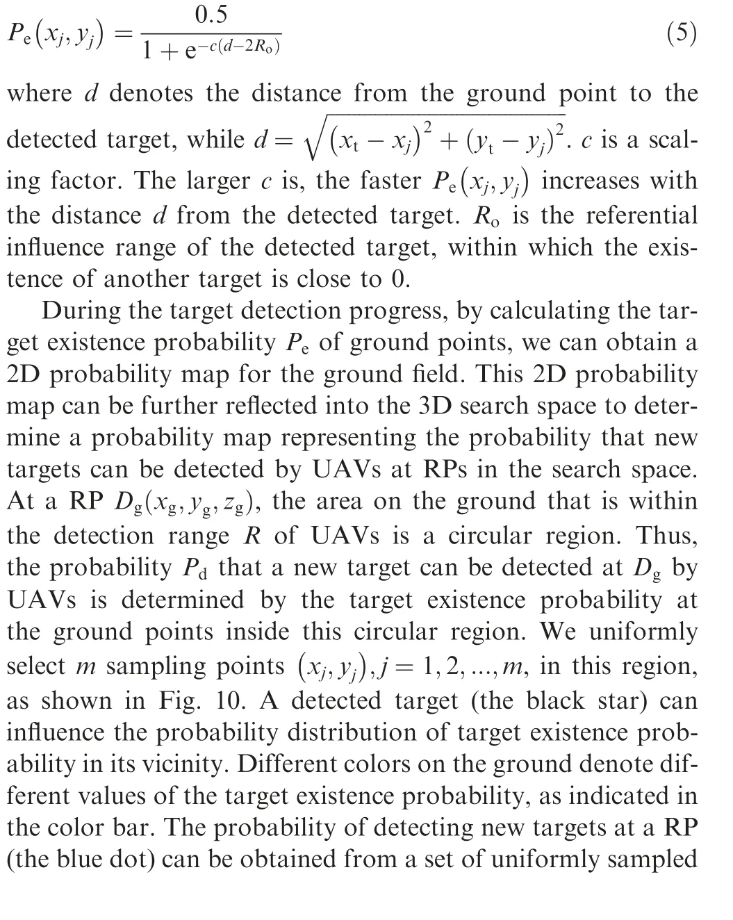
To improve search efficiency, we introduce probabilities into the real-time path planning exercise. Pe(xj,yj) and Pd(xg,yg,zg) are respectively defined as the probability of the presence of a new target at the position(xj,yj) and the probability that a UAV can detect a new target at the position(xg,yg,zg).
Initially,Peis preset as 0.5,which means that the probabilities of existence and non-existence of a target are the same.In the case that targets are scattered in the mission field, we assume that within a certain distance from a detected target Tj, Peis close to 0. Beyond this range, Peincreases gradually,and finally approaches 0.5. With this target placement model,we adopt the sigmoid function to approximate the probability distribution of Pe. Peat a ground point (xj,yj) around the detected target (xt,yt) is established as

Function F denotes the reflection from 2D ground probability map to the 3D probability map in the search space.Three different metrics are studied to determine the probability value in the 3D probability map from the 2D map: weighted centroid,35–37maximum value and average value.
The weighted centroid method is to take the weighted average of the target existence probabilities of the m sampling points in the circular region,while the weight of each sampling point is the inverse of its distance to the center of the circular region.Thus,when a sampling point is closer to the region center, a higher weight will be associated with its target existence probability. In this case, the function F can be formulated as
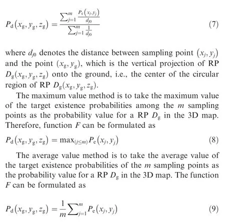
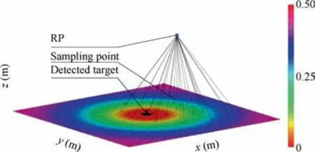
Fig.10 Reflection of target existence probability of ground into target detection probability at a RP in search space.
Fig.11 represents the probability values in the 3D probability map, obtained respectively by the weighted centroid method, maximum value method and average value method,after one target(black star)is detected.Different colors denote different values of the target detection probability,as indicated in the color bar. In the area close to the detected target, the probability value is close to 0 and grows to 0.5 as the distance to the detected target increases.Fig.11(a)is the map obtained by the weighted centroid method, Fig. 11(b) is the map obtained by the maximum value method, and Fig. 11(c) is the map obtained by the average value method. The three sub-figures exhibit different patterns in the transition phase of the probability value,from 0 to 0.5.Despite the differences,in all the three sub-figures,the probability values in the vicinity of the detected target are reduced.In the area close to the position of the detected target, the probability value is close to 0.As the distances to the detected target increase,the probability values increase accordingly and finally approach and maintain 0.5, the upper limit of the probability value in the map. The probability distribution in the map is in accordance with the expectation in our assumption, which also proves the efficacy of using sigmoid function to model the probability distribution. The effects of the three different probability value calculation methods are investigated later in our experimental study.
3.4.2.Real-time path planning using KM algorithm improved by 3D probability map
Upon getting the 3D probability map,we incorporate the variation of target detection probabilities into the real-time path planning process of UAVs. To do this, we modify the weights between UAVs and RPs in KM algorithm under the guidance of the 3D probability map.The weight between a UAV Uiand a RP Djis updated as the product of the inverse of distance Sij,i.e.,1/Sij,and a power function of the probability value PDjat Djin the probability map.Therefore,higher probability values of RPs will increase their assignment weights to UAVs, and correspondingly, improve their priorities of being assigned to UAVs. After modification, the new assignment quality, i.e.,the new weight,of assigning RP Djto UAV Uiis formulated as

where Q(i,j)modifiedis the modified weight representing the quality of assigning RP Djto UAV Ui. As shown in Fig. 12,Sijis the distance between UAV Uiand RP Dj.PDjis the probability value of detecting new targets at Dj.Thus,with a smaller distance Sijand a higher probability value PDj, the weight Q(i,j)modifiedwill be larger so that there is a higher probability of assigning UAV Uito RP Dj.The constant α can be adjusted according to the situations. Since PDjis no more than 0.5, a smaller α makes the probability value more dominant than the distance in RP assignment.
The new objective function to be minimized for RP assignment can be formulated as

The solution M to objective function Eq. (11) is the designation of RPs to a UAV swarm that maximizes the assignment quality. The diagram of RP assignment using improved KM algorithm is shown in Fig.12.Each UAV/RP pair is associated with a weight, i.e., the assignment quality Q(i,j)modified. UAVs are assigned to RPs to maximize the sum of Q(i,j)modifiedbetween Uiand its assigned RP Dj, for i=1,2,···,NM.
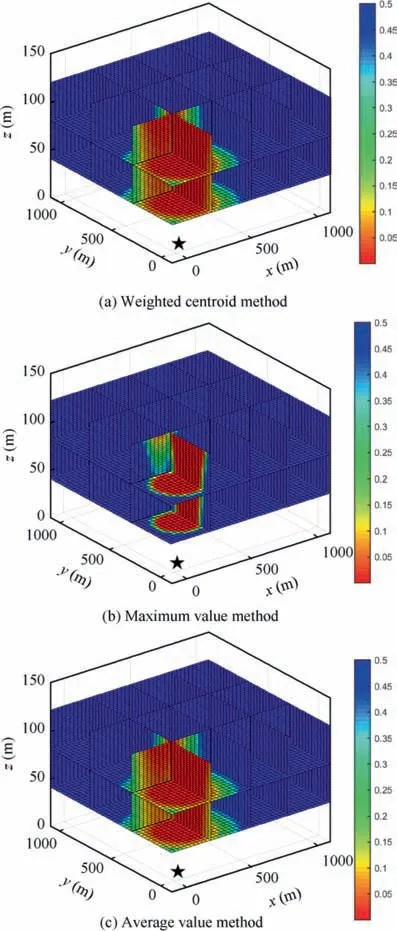
Fig. 11 3D probability maps built with three different methods.
4. Experimental study
In Section 3,we have described the proposed method for target detection in an unknown area.We have proved that UAVs can detect all the targets by traversing the RPs,despite of the density of the targets, the distributions of the targets, and the detectable directions of the targets.To improve the search efficiency under the assumption that the targets are scattered in the mission field,we have introduced a real-time path planning method using improved KM algorithm. To visually demonstrate the result of the proposed method, and to investigate the efficacy of the three different probability calculation methods in Section 3.4,we carry out an experimental study to simulate the search process using a UAV swarm. The simulation platform is established in MATLAB.
4.1. Simulation environment
Without loss of generality,we set both the length and width of the mission field G as 1000 m. Since we have already proved that the proposed method can detect targets with any density,distribution and direction, i.e., the number and the detectable directions of the targets will not affect the ability of the proposed method, we put a number of 25 targets in G.The direction of the region where target Tjcan be detected,described by φTjand θTj, are generated randomly. The scales of the detection ranges γTjare also randomly generated.The only information that the UAV swarm knows about the target is that γTjare no less than 120°. The number of UAVs in the mission will only influence the search speed because with more UAVs,the RPs can be traversed more quickly, and the mission can be done with less time spent.Therefore, without loss of generality, we use a UAV swarm of 20 UAVs to search for the targets. The detection range of UAVs is set as RUi=150 m for i=1,2,···,20. Here we adopt these parameters just to illustrate and visualize the search result. All the parameters above can also be set as other values according to the actual requirements.
4.2. Detection results using KM algorithm
Fig.13 shows the search results using KM algorithm based on the distances between UAVs and targets. The yellow asterisks denote the RPs which are set using the proposed method.The blue dots record the locations of UAVs at every moment during the search process.Once a RP has been visited by a UAV,it will be marked with a red circle around it.And when a target is detected by a UAV, it will be marked with a black star. In this scenario, targets are uniformly distributed in the mission field.
It can be seen from the search result that all the targets have been detected and marked as black stars, which manifests the effectiveness of the proposed method. During the search process, UAVs have visited most of the RPs and flown relatively long distances.In this scenario,when a target is detected,there is no necessity to visit the rest of its neighboring RPs because there are no other targets in the surroundings of the target.However, in this path planning exercise using the distancebased KM algorithm, UAVs will continue to traverse the neighboring RPs of the detected target because of their small distances from these RPs, without considering the low probability of detecting new targets.This consumes extra computing time. Therefore, in the next subsection, we test the improved KM algorithm under the same scenario.
4.3. Detection results using improved KM algorithm
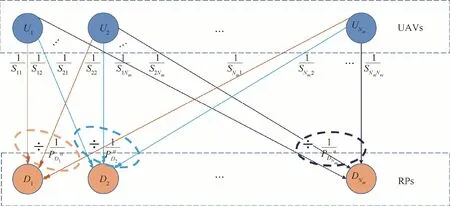
Fig. 12 Schematic diagram of RP assignment using improved KM algorithm.
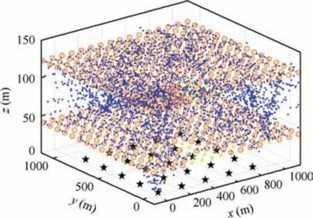
Fig. 13 Detection using KM algorithm based on distances between UAVs and targets.
As illustrated in Section 3.4,the improved KM algorithm aims to assign UAVs to the RPs with higher targets detection probability and lower flight distance,so that the search cost can be reduced. During the mission, the probability map is updated whenever a new target is detected.RPs in area with high probability value can have higher priority to be visited. Fig. 14 shows the update of 3D probability map in the search process,as the number of detected targets increases. Different colors denote different values of the target detection probability, as indicated in the color bar. The probability maps shown in Fig. 14 are calculated using the weighted centroids method.With the discoveries of new targets, from 1 to 8, 16 and 22,the probability values on probability map change between 0 and 0.5. It can be observed from Fig. 14 that in areas where many targets are detected, the probability value is low, and in areas where potential targets wait to be detected, the probability value is high.The probability map reflects the expected and desired probability distribution.
The detection using improved KM algorithm is shown in Fig. 15. Compared with the results of the distance based KM algorithm in last subsection, under the same scenario,the number of RPs visited (red circles) and the number of trajectory points flown (blue dots) by UAVs have significantly decreased.
4.4. Result analysis
In order to further investigate the efficacy of the improved KM algorithm, we carry out target detection simulations under twenty search scenarios using the distance based KM algorithm, improved KM algorithm as well as Genetic Algorithm(GA) which is one of the most commonly used optimization algorithm for search path planning.38The 3D probability maps in the improved KM algorithm are calculated using the weighted centroid method,average value method and maximum value method, respectively. In other words, each of the twenty scenarios has been run 3 times with different probability calculation methods in the improved KM algorithm and run another two times using GA and the distance-based KM algorithm.
In the first ten scenarios, the targets are uniformly distributed in the mission field. The targets information and the search results are shown in Table 2.φ(rad)and θ(rad)are randomly generated to describe the direction of the detectable region. Dcentroid, Daverage, Dmaximum, DGAand D0represent the total flight distance flown by the UAV swarm during detection using weighted centroid method, average value method, maximum value method,GA and KM algorithm without probability maps, respectively.
In the last ten scenarios,the targets positions and directions are generated randomly. The targets information and the search results of the last ten scenarios are shown in Table 3.x(m) and y(m) are generated randomly. Dcentroid, Daverage,Dmaximum, DGAand D0represent the total flight distance flown by the UAV swarm during detection using weighted centroid method, average value method, maximum value method, GA and KM algorithm without probability maps, respectively..
In the twenty scenarios, all the targets are detected by UAVs. Dcentroid, Daverage, Dmaximum, DGAand D0represent the total flight distance flown by the UAV swarm during detection using weighted centroid method, average value method, maximum value method,GA and KM algorithm without probability maps, respectively. Table 4 shows the average flight distance in the first ten scenarios and the last ten scenarios using the four different methods.
It is confirmed that,no matter which path planning method is adopted, the search efficiency of the improved KM algorithm is obviously higher than the commonly used GA and the normal KM algorithm without 3D probability map, with a flight distance reduction by 23.4%–78.1% in the twenty search scenarios.
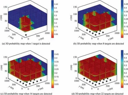
Fig. 14 Update of 3D probability map in search process as the number of detected targets increases from 1 to 8, 16 and 22.
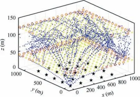
Fig. 15 Detection using KM algorithm improved by 3D probability maps.
However, different probability calculation methods exhibit different effects.Weighted centroid method has resulted in the highest search efficiency with an average flight distance of 35880 m under uniform target distribution and 44100 m under random target distribution, while the maximum value method is least efficient with an average flight distance of 70380 m and 62820 m, and the average value method exhibits medium performance with an average flight distance of 49740 m and 51480 m. On one hand, this may be because the weighted centroid method can better incorporate the target existence probability on the ground into the target detection probability value in the 3D map.On the other hand,the maximum value method only takes the highest target existence probability in the sampling region as the value of the target detection probability at the RPs, which is likely to misguide UAVs flying towards areas whose overall target detection probability is lower than other areas.
For most target detection tasks, the distribution of targets always has a certain rule,and the method in this paper is based on this assumption.Therefore,comparing the detection results of the two types of targets distribution, we can find that the improved KM algorithm based on the 3D probability map has better performance in the detection of uniformly distributed targets, in terms of average flight distance reduced by up to 66.9%. However, for randomly distributed targets,the method in this paper also significantly reduces the average flight distance by up to 58.0%. This is reasonable because when the distribution of targets is more uniform, it will better fit our assumption in the target distribution probability. Generally speaking, the improved KM algorithm can largely increase the search efficiency while still promising the detection of all targets, especially under the situation where targets are uniformly distributed.
5. Conclusions
In this paper,by focusing on the detection of unknown targets using a UAV swarm, a complete and effective detection method is proposed. Considering the detectable directions of targets,we come up with a search space disintegration method which can provide waypoints, i.e., RPs, for the UAV swarm.We demonstrate that a complete detection of the targets can be achieved by traversing the RPs. To further improve the search efficiency, we introduce detection probabilities into our method. A real-time 3D probability map is built in the search space with the information from detected targets.Based on the map,an improved KM algorithm is proposed for UAV real-time path planning.The results of experimental studies on 20 different search scenarios show that the method proposed in this paper can realize the complete detection of targets with different distributions. Moreover, under the guidance of the3D probability map, the search efficiency has been largely improved, especially when the targets are uniformly distributed. The study in this paper considers the characteristics of the targets and is the improvement to the existing methods which are mainly based on the spatial relationship between UAVs and targets. The results of this paper will further advance the ability of UAV swarms to perform reconnaissance and other more complex tasks.
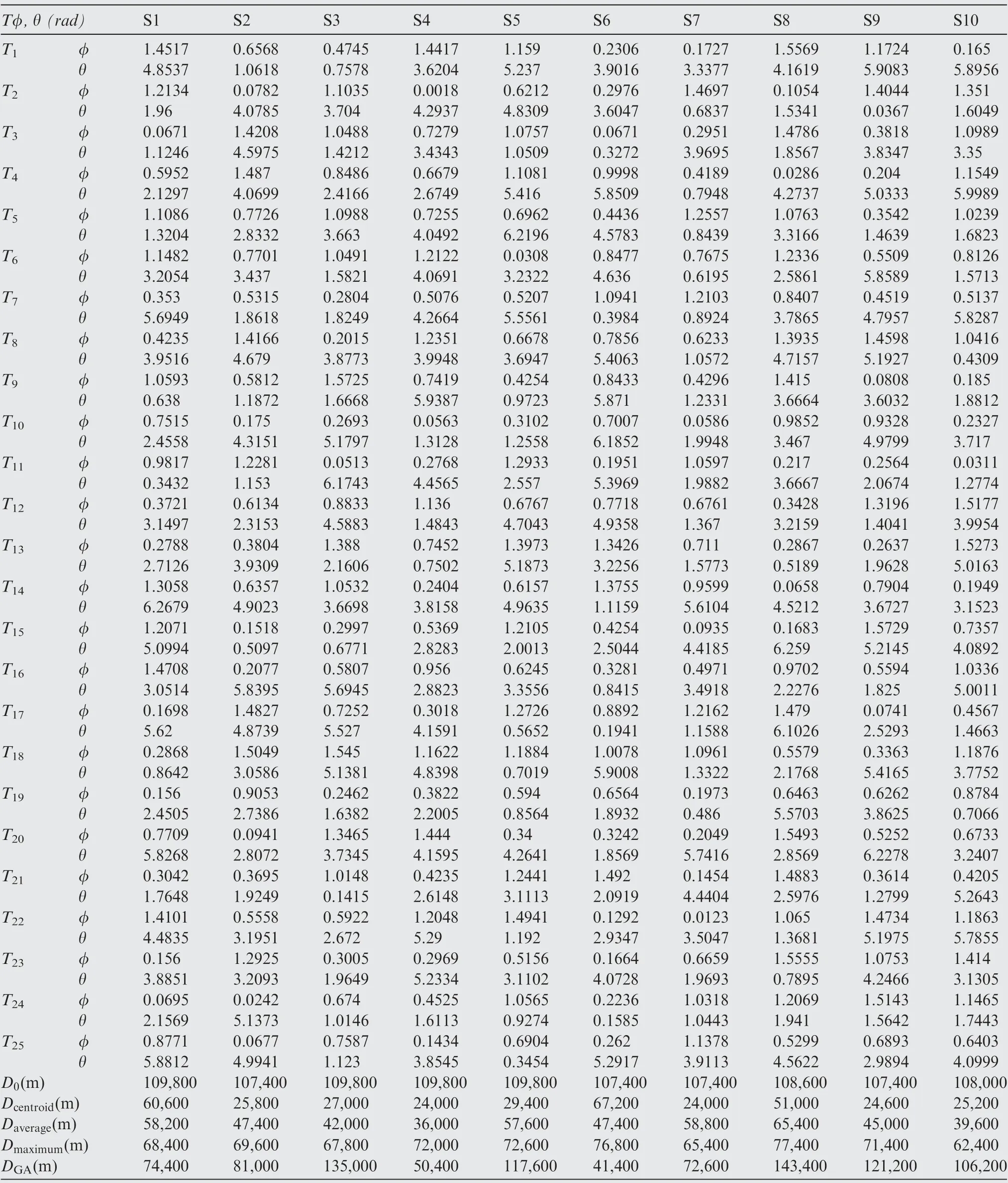
Table 2 Targets information and search results of the first ten scenarios when the targets are uniformly distributed.
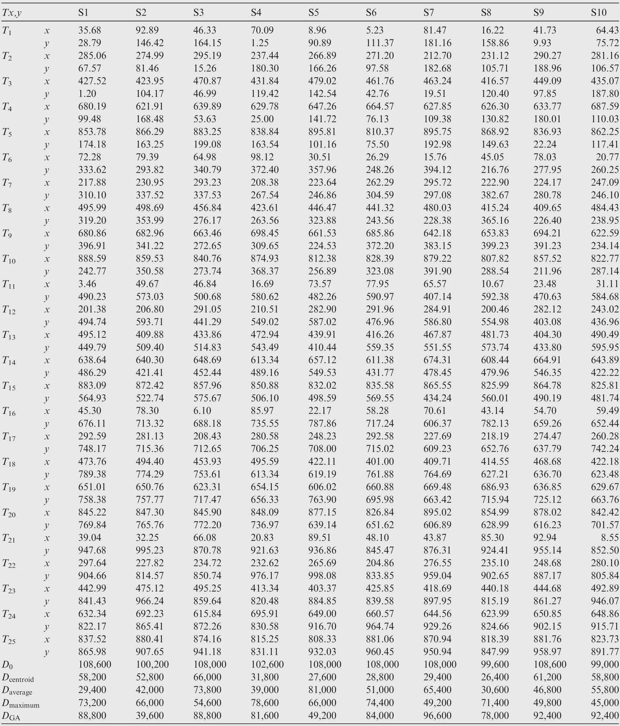
Table 3 Targets information and search results of the last ten scenarios (unit: m).

Table 4 Comparison of average flight distance using different methods under different distributions of targets.
Declaration of Competing Interest
The authors declare that they have no known competing financial interests or personal relationships that could have appeared to influence the work reported in this paper.
 CHINESE JOURNAL OF AERONAUTICS2021年2期
- CHINESE JOURNAL OF AERONAUTICS的其它文章
- Recent active thermal management technologies for the development of energy-optimized aerospace vehicles in China
- Electrochemical machining of complex components of aero-engines: Developments, trends, and technological advances
- Recent progress of residual stress measurement methods: A review
- Micromanufacturing technologies of compact heat exchangers for hypersonic precooled airbreathing propulsion: A review
- Towards intelligent design optimization: Progress and challenge of design optimization theories and technologies for plastic forming
- A combined technique of Kalman filter, artificial neural network and fuzzy logic for gas turbines and signal fault isolation
