Numerical and experimental investigation on dynamic performance of bump foil journal bearing based on journal orbit
Yu ZHOU, Longto SHAO, Cn ZHANG, Fenzhu JI,*, Jing LIU,Guo LI, Shuiting DING, Qi ZHANG, Frong DU
a School of Transportation Science and Engineering, Beijing Key Laboratory for High-efficient Power Transmission and System Control of New Energy Resource Vehicle, Beihang University, Beijing 100083, China
b School of Energy and Power Engineering, Aircraft/Engine Integrated System Safety Beijing Key Laboratory, Beihang University, Beijing 100083, China
KEYWORDS Bump-type foil journal bearing;Dynamic performance;Experimental method;Journal orbit;Numerical calculation
Abstract Widespread usage of bump-type foil journal bearing (BFJB) in oil-free microturbomachinery requires accurate predictions of dynamic performance characteristics, although it remains a challenging issue because BFJB reflects nonlinear both structurally and aerodynamically.This paper presented a simple experimental method to semi-directly obtain the minimum film thickness and dynamic stiffness of BFJB using the journal orbit.Numerical calculations and simulations are conducted to validate the experimental method.The micro-deformation and interaction of various foils are taken into consideration to improve the model precision.The results from the numerical model regarding the BFJB dynamic characteristics are compared with the experimental results coming from a dedicated test rig,which shows that the experimental results fluctuate obviously and agree not well with the numerical results at the start stage due to the presence of dry friction at that time,nevertheless,they show fantastic agreement as soon as a gas film is gradually generated to separate the shaft from the top foil.Therefore,the proposed experimental method is effective to predict film thickness and dynamic characteristics during the period from the lift-off time to the land-off time.The dynamic characteristics,along with the journal orbits also can be used to rapidly predict the dynamics behavior of rotor-bearing systems.
1. Introduction
Bump-type foil journal bearing (BFJB) is compliant, selfacting hydrodynamic air bearing which consists of a top foil,corrugated bump foils, a shaft and a bearing housing (as shown in Fig. 1). Compared with oil-lubricated bearings,despite lower load-carrying capabilities, BFJBs have distinct advantages of high stability, high operating speed and high efficiency,thereby become more prevalent in high-speed turbomachinery.Dynamic characteristics of BFJB can be characterized by dynamic stiffness and dynamic damping coefficient,which directly affects the rotor dynamics behavior and needs to be obtained before rotor dynamics analysis. Furthermore,the predictability of their dynamic behavior is still matter of study, unlike oil-lubricated bearings, where such problem has already been solved to a great extent.
Scholars have conducted several significant experimental and theoretical studies on the dynamic characteristics. Experimental methods to identify dynamic coefficients include Time-Domain Least Squares Method,1,2Frequency-Domain Identifying Method3and Excitation Method et al. Heshmat et al.4–6early presented an experimental procedure to identify the dynamic coefficients by excitation method.On the basis of this,Rubio and Andres7predicted the structural dynamic characteristics using single frequency loads of varying magnitudes.Moreover, Andres et al.8–10have also conducted experimental studies on the rotordynamics performance of air bearings.Feng et al.11–13tested the stiffness and damping of hybrid bump-metal foil bearings and investigated the effects of misalignment on dynamic characteristics of BFJB. Recently,vibration response of BFJB14–16under different conditions are researched. And the rotordynamic evaluations of a rotorbearing system supporting a large overhung mass are presented by LaTray and Kim17.Indeed,significant achievements have been obtained in various tests of BFJB dynamic characteristics. However, corresponding to the current test methods,the dynamic coefficients can only be indirectly obtained through vibration behavior.It needs to acquire a large number of time-domain data and conduct a Fourier transform to get frequency-domain data, which causes expensive computation and high test cost. In addition, BFJB cannot be loaded arbitrarily during the experiment.
Compared with the experimental study,the theoretical study on the dynamic behavior of BFJB falls behind obviously. The most commonly used method is to model the foil structure and then to solve the compressible gas lubrication Reynolds equation coupled with the foil deformation.Lund and Oreutt18first proposed 4 dynamic stiffness coefficients and 4 dynamic damping coefficients.And then Heshmat et al.19used the small perturbation method to solve those dynamic coefficients.Next,scholars began to model various foil structures, such as beam model20,spring model21,22,shell model23.24and more elaborate models25–27.On the basis of these models,film thickness and film pressure can be calculated to obtain the dynamic coefficients by coupling the compressible gas lubrication Reynolds equation and foil structure equation. Moreover, some scholars tend to simplify the models to improve computational efficiency28–31.However,the modelling difficulties are inevitable because BFJB is nonlinear both structurally and aerodynamically. Most of these models or algorithms have been simplified more or less but have not exactly embodied the interactions between the foils and film pressure,and foil micro-deformation has not been discussed in depth, which add obstacles to reliably predict BFJB dynamic performance characteristics.
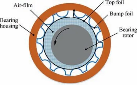
Fig. 1 Schematic diagram of BFJB.
As evidenced in the literature survey32–34, BFJB dynamic characteristics reflects rotor supporting conditions and journal orbit determines rotor operation state, they are all indispensable to obtain dynamics of rotor-bearing systems. According to the previous analyses35–37, BFJB dynamic characteristics is generally obtained by indirect experimental methods which are complex and costly.If it can be rapidly estimated by virtue of journal orbit,experiments will be greatly simplified. Consequently, this paper builds a relationship between BFJB dynamic characteristics and journal orbit, presents a simple experimental method to measure the minimum film thickness and dynamic stiffness using the journal orbit. Moreover,numerical calculations and simulations are conducted to validate the experimental method based on the two-dimensional shell element model, taking into account the microdeformation and interactions between various foils, which is closer to the actual situation and makes the calculation result more accurate. The finite difference method is used to solve dynamic gas-lubricated Reynolds equation so as to obtain the numerical results with respect to dynamic stiffness and dynamic damping.The rest of this paper is organized as follows.In section 2,a new BFJB test rig and various test BFJBs are designed to measure journal orbits,then to predict minimum film thickness and dynamic stiffness.Section 3 demonstrates the numerical model of BFJB considering foil micro-deformation and conducts the corresponding simulations respectively on film pressure and dynamic characteristics. In section 4, the experimental results are depicted and compared with the numerical results to validate feasibility of proposed experimental method.This is followed by the conclusion in the final section.
2. Experiment
2.1. Description of test BFJB

Fig. 2 Designed bearing in measurement.
Fig. 2 demonstrates the test BFJBs. The top foil and 7 bump foils arranged axially are respectively fixed on the bearing housing by high-temperature structural glue. 6 various BFJBs(as shown in Table 1 and Table 2)are designed for comparison test to investigate that how the structural parameters (as shown in Fig. 3) influence the BFJB performance.
The test BFJBs are formed by bulging process and Fig.4(a)illustrates the forming template. Fig. 4(b) and Fig. 4(c) manifest the stainless steel foils before and after bulging, respectively. The assembled bearings are shown in Fig. 4(d).
2.2. Configuration of test rig
Two HZ-8500 eddy current displacement sensors, as shown in Fig.5(a),are arranged to be perpendicular to each other,at an equal distance from the bearing housing and at a 45 degree angle to the horizontal direction as shown in Fig. 5(b). The whole rotor system is manifested in Fig. 5(c) and LMS SC305 with a range of 20 kHz is adopted to collect vibration and noise data,as shown in Fig.5(d),while the sinusoidal frequency resolution is 1 mHz. Moreover, the sensor used in the test is an eddy current displacement sensor38in the HZ-8500 series with a range of 1.5 mm, the nominal sensitivity of 8 mV/μm, and the sensor operating frequency of 4 kHz.Detailed parameters are shown in Table 3.
The data sampling frequency is set to 8 kHz,which can satisfy the requirements of the sensor operating frequency,reduce the amount of data acquisition and make sure that the data is not distorted.
The test adopts high-precision and high-speed electric motor,which satisfies rated rotating speed and starting torque requirements. External vibration is depressed on the test through improving mass of test bench base. The highest measurable speed reaches 150,000 r/min.
Fig. 6 and Fig. 7 demonstrate the schematic diagram and the photo of BFJB test rig, respectively. The test BFJB floats on the rotor connected to a motor with a maximum speed of 60,000 r/min through a flexible coupling,which can make load be arbitrarily applied to bearing housing without affecting the working of BFJB. The test rig is based on the bearing rotor and the load is applied to the bearing house. The radial displacement of the bearing rotor is extremely small,thus the load generated by the flexible coupling can be negligible compared with the lifting road.
2.3. Journal orbit test
The data from the two displacement sensors within 1 second are acquisited as soon as the BFJB has fully lifted off and reached steady state, which are transformed into horizontal and vertical coordinate dimensions.According to these coordi-nate dimensions,we can draw various BFJB journal orbits versus load,rotation speed,and foil structure,respectively.All the journal orbits in this paper take the whirling center as the coordinate origin.

Table 1 Different parameters of test BFJBs.

Table 2 Same parameters of test BFJBs.
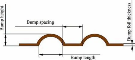
Fig. 3 Configuration of bump foil.

Fig. 4 Test bearing preparation.
Fig. 8 manifests the journal orbits of Bearing 1 on various rotation speeds at 5.2 kg load.ω denotes the rotation speed of BFJB,X denotes the amplitude of journal orbit in the horizontal direction, Y denotes the amplitude of journal orbit in the vertical direction. Whirl amplitude of journal orbit reaches a maximum at 12,000 r/min and then greatly reduces as the rotation speed increases from 18,000 r/min to 24,000 r/min.Whereas it makes little change with the rotation speed further increases, which indicates that the bearing has been brought into a steady state and operates smoothly. In particular, it reflects the smoothest operation at 48,000 r/min.
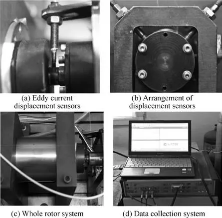
Fig. 5 Configuration of test rig.

Table 3 Equipment parameters.

Fig. 6 Schematic diagram of BFJB test rig.
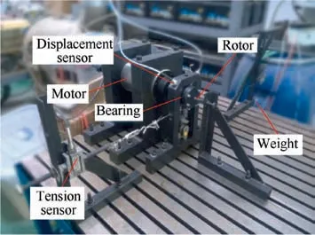
Fig. 7 Overall structures of BFJB test rig.
Fig. 9 illustrates the journal orbits of Bearing 1 on various loads at 54,000 r/min. W denotes the load of BFJB. Whirl amplitude is almost doubled from 5 μm to 10 μm as the load increases from 1.2 kg to 9.2 kg and the growth is mainly concentrated in the vertical direction.That means the journal orbit is first close to an approximate-circle at light load and then becomes an ellipse as the load increases. The major axis of the ellipse is in accordance with the load direction, growing obviously with the increase of the load. As a BFJB, it can be inferred that the whirl amplitude also grows with the increase of the eccentricity due to a correspondence between load and eccentricity.
Fig.10 manifests the journal orbits of Bearing 1,Bearing 3 and Bearing 6 on various loads from 1.2 kg to 7.2 kg at 42,000 r/min, respectively. Whirl amplitude of Bearing 3 doubles that of Bearing 1 at the same load, which indicates that whirl amplitude of BFJBs grows with the bump length increases. The main reason for this phenomenon is that the BFJB with larger bump length results in serious foildeformation, which requires the eccentricity being large enough against bearing load. Whirl amplitude of Bearing 6 is much larger than that of Bearing 3 on load 1.2 kg at 42,000 r/min, which mainly because the bearing has resonated at this time.
2.4. Minimum film thickness and dynamic stiffness prediction based on journal orbit
Compliant foils and shaft contact each other and develop the friction at low speed during the start and stop stages because there is no air-film formed at that time. Lift-off refers to that compliant foils and shaft separate completely and a stable air-film begins to form.Fig.11 illustrates a schematic diagram of testing the minimum film thickness based on the rotor orbit39in this paper.The locations of rotor-center are disorganized at the start stage and then become regular as soon as the BFJB starts to lift-off.T0denotes lift-off time.The average displacement difference of rotor-centers in y direction, respectively, when BFJBs are in the static and steady states can be considered as the minimum film thickness δ0in this condition,which can be obtained based on the journal orbits in various states.
As all we known that dynamic principal stiffness can be calculated directly by means of the load divided by the displacement in corresponding direction, BFJB dynamic principal stiffness coefficients are able to be obtained by this simple straightforward way because we can load as we need in our test rig and obtain the corresponding displacement by journal orbits.For instance,as shown in Fig.12,0.5 kg load in y direction causes ζYwhich can be obtained by various journal orbits before and after loading. All the dynamic principal stiffness coefficients for various BFJBs from Bearing1 to Bearing6,for various speed from 12000 to 54000 r/min and every 6000 r/min, for various loads from 1.2 kg to 9.7 kg and every 0.5 kg are measured and calculated in our test rig.

Fig. 8 Journal orbit versus rotational speed (W=5.2 kg load).

Fig. 9 Journal orbit versus load (ω=54000 r/min).
Although this method is conductive to fast predict BFJB dynamic characteristics, the predictions during the start and stop stages are considered less credible because dry friction between shaft and complaint foils makes journal orbits be unsteady at that time. Hence, lift-off time and lift-off speed need to be identified precisely to distinguish the credible dynamic characteristics and minimum film thickness from the predictions. As shown in Fig.13,the lift-off time is identified on the premise of accurate measurement of the drag torque. As the rotor starts and accelerates to a maximum speed,a sharp peak appears in the BFJB drag torque,which indicates the presence of dry friction between the shaft and the top foil.The drag torque drops and then tends to be a steady smaller value from T0,which suggests that an air-film is gradually generated to separate the shaft from the top foil and the BFJB starts to lift-off. As the rotor decelerates from the land-off time, the drag torque also manifests a sharp peak before the rotor stops. In this paper, the speed where the drag torque starts to be unchanged is identified as the lift-off speed when the BFJB starts to fully suspended.The determinant condition is relatively strict,which results in the measured lift-off speed is higher than that in other literatures.
3. Numerical calculation and simulation
3.1. Numerical model
Harmonic disturbance has a great influence on the dynamic coefficients of the air bearing. In this chapter, the effect of speed and frequency on the dynamic coefficients are studied by using small disturbance method combined with twodimensional shell element elastic-support model. As shown in Fig. 14, in the cylindrical coordinate system, the rotor relies on the film pressure between the compliant surface and the shaft surface to achieve non-contact suspension,where h is film thickness, e is eccentric distance, and e0is eccentric distance when bearing keep at equilibrium position. The dimensionless compressible gas-lubricated Reynolds equation under isothermal condition can be written as:


Fig. 10 Effect of foil structure on journal orbit (ω=42000 r/min).

Fig. 11 Schematic diagram of the minimum film thickness measurement.

Fig. 12 Schematic diagram of dynamic stiffness measurement.

Fig. 13 Schematic diagram of the lift-off speed identification.

Fig. 14 Shaft position at any perturbation.
where εcis disturbed eccentricity amplitude, φcis disturbed attitude angle amplitude,i denotes imaginary unit,Ω-is dimensionless shaft perturbation frequency and wfis dimensionless foil micro-deformation. The film thickness at any angle θ between the shaft surface and the compliant surface can be written as:

Introduce Eq.(5)into Eq.(1)to simplify and omit the highorder term, the dynamic gas-lubricated Reynolds equation is:

K denotes dynamic stiffness,and C denotes dynamic damping. Subscripts indicate the stiffness coefficients and damping coefficients of the different coordinate systems and directions.
3.2. Radial deformation of foil
Fig.15 depicts the force diagram of the top foil,while M0is the bending moment of A and B, WTis the concentrated load of top foil, F0is supporting reaction of top foil received from bump foil, m is the horizontal distance from fix point on the left, s is wavelength of bump foil, l is horizontal distance between force and fix point on the left.
The differential equation of the radial deformation wTof the top foil is:


Fig. 15 Force diagram of top foil.
where M denotes the bending moment of top foil, DTdenotes the bending rigidity of top foil.
The dimensionless parameters are defined as follows:

3.3. Reynold equation solution
The finite difference method is used to solve Reynolds equation in this paper. The difference format can be constructed through Taylor series expansion, therefore, Taylor series expansion in the neighborhood of xican be denoted as:

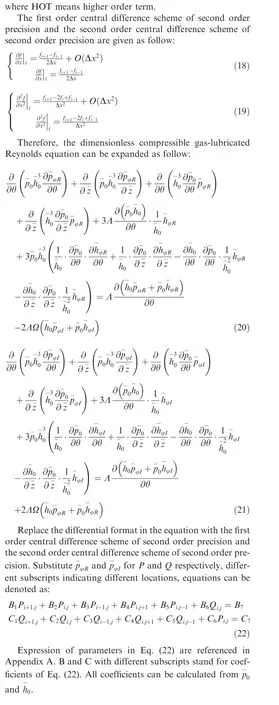
3.4. Numerical results and discussion
According to the above analyses, dynamic characteristics of BFJB are calculated.Furtherly,influences of perturbation frequency,eccentricity and foil parameters on dynamic characteristics are discussed.
Fig. 16 illustrates the dynamic stiffness coefficients versus speed for Bearing 1 under eccentricity of 0.6 and perturbation frequency of 50 Hz. As the rotation speed increases, the absolute values of all the stiffness coefficients increase. This is mainly because the increase of the speed makes the film pressure increase, which results in the dynamic stiffness coefficient increasing. It can be also inferred that the load capacity increases as the speed of the shaft increases due to the film pressure, similarly to eccentricity. Fig. 17 manifests the dynamic damping coefficients versus rotation speed. |Cyy|and |Cyx| vary little with speed, whereas |Cxx| and |Cxy| raise as the speed increases because the increasing speed leads to the growth of air velocity and damping.
Fig. 18 exhibits the effect of perturbation frequency on the dynamic stiffness coefficients for Bearing 1 at 54000 r/min.The dynamic stiffness coefficients change obviously at first and then tend to be various steady values as the perturbation frequency increases.The reason is that when the perturbation frequency is relatively low, it exerts a great effect on air-film,which causes sharp change in stiffness. Nevertheless, when the perturbation frequency is much larger than the selfexcitation frequency of the air-film,the dynamic stiffness coefficients are little affected by the perturbation frequency. The main stiffness coefficient firstly decreases and then rises, and tends to be stable finally.The main stiffness coefficient on vertical direction change little due to its own weight,while that on horizontal direction is easily affected by perturbation frequency.
Fig. 19 illustrates the effect of perturbation frequency on the dynamic damping coefficients. As the perturbation frequency increases, all damping parameters approach to 0 since 3000 Hz. This indicates that the BFJB cannot provide adequate dynamic damping as the perturbation frequency gradually increases to a specific value, which cause the BFJB be unstable.
Fig.20 demonstrates the effect of foil structure on dynamic stiffness coefficients from Bearing 1 to Bearing 6. |Kyy| and |Kxy| change significantly because the bearing load is applied in the vertical direction, whereas |Kxx| and |Kyx| reflect little change with the growth of eccentricity. In addition, |Kxx|and |Kxy| are larger if the bearing has larger bump length and foil thickness. Conversely, |Kyx| and |Kyy| of BFJB with larger bump length and foil thickness are smaller.
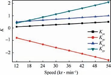
Fig. 16 Dynamic stiffness versus speed.

Fig. 17 Dynamic damping versus speed.
3.5. Simulation analysis
In order to understand how the compliant foil deformation affects BFJB dynamic characteristics, two finite element models which are different on whether to consider compliant foils deformation are established to analyze film pressure distribution, film thickness distribution and BFJB compliant foil deformation. Fig. 21 manifests the film pressure distribution of Bearing1 at the eccentricity ε=0.6, which neglects the foil deformation. Conversely, Fig. 22 considers the foil deformation. It can be seen that there are high positive pressure area and high negative pressure area in air-film pressure distribution.The film pressure in Fig.22 is deformed locally and shows‘‘corrugated”in the high pressure area due to the fluctuation of the film thickness, which indicates the foil deformation influences the dynamic performance characteristics. Meanwhile, it can be proved that the two-dimensional shell element model can excellently simulate the deformation of the elastic foil.The calculation result of the film pressure agrees well with the actual situation.
Fig.23 manifests the film thickness distribution of Bearing1 at the eccentricity ε=0.6,which neglects the foil deformation.Conversely, Fig. 24 considers the foil deformation. The film thickness in Fig. 23 is smaller than that in Fig. 24 due to the negligence of the compliant foil deformation. And the film thickness which considers the foil deformation shows ‘‘corrugated” in the high film pressure area, which affects film pressure in turn and proves that BFJBs are self-adaptive.
In order to verify the calculation formula in Eq.15,Fig.25 and Fig.26 illustrate the bump foil and top foil deformation at the eccentricity ε=0.6, respectively. U denotes the foil deformation displacement, U2 denotes the foil deformation displacement in y direction. The foil deformation decays from the middle to the fixed and free ends in the circumferential direction.And in the axial direction the deformation decreases toward two ends, which proves the validity of Eq. (17).
4. Results and discussion
In order to validate the implemented experimental method to predict BFJB dynamic characteristics and minimum film thickness, its results are compared to numerical and simulation results. In this section, EX indicates the experiment results,BET and BEST indicate the numerical results which neglect and consider the foil deformation, respectively.

Fig. 18 Effect of perturbation frequency on dynamic stiffness.
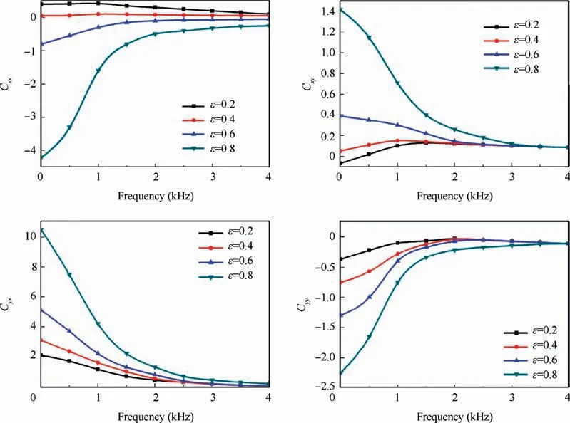
Fig. 19 Effect of perturbation frequency on dynamic damping.

Fig. 20 Effect of foil structure on dynamic stiffness.

Fig. 21 Film pressure neglecting foil deformation.

Fig. 22 Film pressure considering foil deformation.

Fig. 23 Film thickness neglecting foil deformation.
Fig.27 manifests the air-film thickness versus load for Bearing5 at different speeds. The air-film thickness reflects an approximate linear decrease with the load increases at a specific speed.When the load is fixed,the faster the speed is,the larger the film thickness is. Fig. 28 depicts the comparison of predictions by numerical method to experimental results in air-film thickness on various loads. The air-film thickness roughly shows a quadratic increase trend with speed increases.In addition, the experimental results fluctuate obviously and agree not well with the numerical results at low speed due to the presence of dry friction at that time. As the BFJB accelerates to the lift-off speed, EX agrees well with BEST. It proves that the proposed experimental method is feasible to predict film thickness during the floating stage. Moreover, BEST is closer to EX than BET, which indicates that the calculation accuracy is improved on condition that micro-deformation and interaction of various foils is involved into calculation model. Simulation results show that neglect of top-foil deformation leads to the film thickness and film pressure are underestimated, which is consistent with the numerical result.

Fig. 24 Film thickness considering foil deformation.

Fig. 25 Bump foil radial deformation.

Fig. 26 Top foil radial deformation.

Fig. 27 Film thickness versus load.
Fig. 29 demonstrates the comparison of predictions by numerical method to experimental results in dynamic principal stiffness on various loads for Bearing 1 at 48000 r/min. The dynamic stiffness grows as the load increases and they can be approximately described as a linear relationship.BEST also reflects more accurate than BET. Fig. 30 depicts the comparison of predictions by numerical method to experimental results in dynamic principal stiffness on various speeds for Bearing1 at 42 N load. The experimental results agree well with the numerical results as the BFJB reaches the lift-off speed although the difference between them is obvious during the start stage. BEST is smaller than BET at the same speed because larger foils deformation leads to lower dynamic principal stiffness. Under the same condition, BFJBs with larger film thickness reflect lower main stiffness, experimental results of stiffness,as shown in Fig.29 and Fig.30,are lower than the theoretical results which neglect the foil deformation.

Fig. 28 Film thickness versus speed.
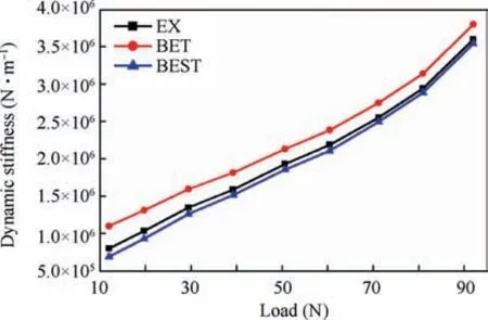
Fig. 29 Comparison of the theoretical and experimental results of dynamic stiffness at different loads.

Fig. 30 Comparison of the theoretical and experimental results of dynamic stiffness at different speeds.
Fig. 31 and Fig. 32 illustrate the waterfall map under noload and load conditions, respectively. 1× denotes the fundamental frequency line, 2× denotes the double frequency line.The bearing under no-load conditions only has amplitude at the fundamental frequency. It can be considered that resonance occurs near 30000 r/min, which results in large amplitude. Fig. 32 shows that BFJB only has amplitude at the fundamental frequency at low speed under load condition,and large amplitude appears near half frequency at high speed.The no-load amplitude seems larger at the same low speed, it can be realized that the amplitude becomes larger as mass grows under the same energy.40

Fig. 31 Waterfall map without load.
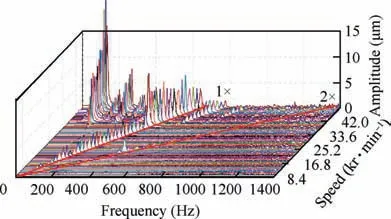
Fig. 32 Waterfall map with load.
5. Conclusions
In this paper,theoretical and experimental investigations have been performed,aimed at the dynamic performance characteristics of a BFJB. A simple experimental method to semidirectly obtain the minimum film thickness and dynamic stiffness of BFJB using the journal orbit is presented. The finite difference method and Taylor series expansion are used to solve various performance of BFJB through numerical calculation based on Reynolds equation.
1) The journal orbits are used to estimate the average displacement difference of rotor-centers in one direction respectively when BFJBs are in the static and steady states, which can be considered as the minimum film thickness. Credible results can be distinguished by the lift-off time when an air-film is gradually generated to separate the shaft from the top foil.
2) The results show that all the dynamic stiffness coefficients change obviously at first and then tend to be various steady values, the dynamic damping coefficients approach zero as the perturbation frequency increases.The various types of dynamic stiffness coefficients reflect different growth trends as the speed and eccentricity increase.
3) The film pressure reflects a corrugated presence in the high pressure area due to the fluctuation of the film thickness when deformation are considered.In addition,the foil deformation decays from the middle to the fixed and free ends in the circumferential direction,which corroborates the film pressure distribution.
4) The comparison between theoretical and experimental results exhibits that the experimental results agree not well with the numerical results during the start stage,nevertheless, they show fantastic agreement as soon as the BFJB begins to lift-off. Therefore, the proposed experimental method is effective to predict BFJB film thickness and dynamic characteristics during the stage from the lift-off to land-off.
Acknowledgements
This work was funded by the Natural Science Foundation of China (No. 51775025, 51205015), China Key Research and Development Plan(No.2017YFB0102102,2018YFB0104100).
Appendix A.


 CHINESE JOURNAL OF AERONAUTICS2021年2期
- CHINESE JOURNAL OF AERONAUTICS的其它文章
- Recent active thermal management technologies for the development of energy-optimized aerospace vehicles in China
- Electrochemical machining of complex components of aero-engines: Developments, trends, and technological advances
- Recent progress of residual stress measurement methods: A review
- Micromanufacturing technologies of compact heat exchangers for hypersonic precooled airbreathing propulsion: A review
- Towards intelligent design optimization: Progress and challenge of design optimization theories and technologies for plastic forming
- A combined technique of Kalman filter, artificial neural network and fuzzy logic for gas turbines and signal fault isolation
