Design of nanofluid-cooled heat sink using topology optimization
Bin ZHANG, Jihong ZHU, Goxing XIANG, Limin GAO
a Department of Engineering Mechanics, School of Mechanics, Civil Engineering and Architecture, Northwestern Polytechnical University, Xi’an 710072, China b MIIT Lab of Metal Additive Manufacturing and Innovative Design, Northwestern Polytechnical University, Xi’an 710072, China c School of Power and Energy, Northwestern Polytechnical University, Xi’an 710072, China
KEYWORDS Forced convection;Heat sinks;Heat transfer;Nanofluid;Sensitivity analysis;Topology optimization
Abstract The paper presented topology optimization of 2D and 3D Nanofluid-Cooled Heat Sink(NCHS).The flow and heat transfer problem in the NCHS was treated as a single-phase nanofluid based convective heat transfer model. The temperature-dependent fluid properties were taken into account in the model due to the strong temperature-dependent features of nanofluids. An average temperature minimum problem was studied subject to the fluid area and energy dissipation constraints by using the density method. In the method, the design variable is updated according to the gradient information obtained by an adjoint based sensitivity analysis process. The effects of the energy dissipation constraint, temperature-dependent fluid properties and nanofluid characteristics on optimal configurations of NCHS were numerically investigated with following conclusions.Firstly, branched flow channels in the optimal configuration increased with the rise of the allowed energy dissipation.Secondly,temperature-dependent fluid properties were significant for obtaining the appropriate optimal results with best cooling performance.Thirdly,heat transfer performances of optimal configurations were enhanced by reducing the nanoparticle diameter or increasing the nanoparticle volume fraction.Fourthly,the optimal configuration for nanofluid had better cooling performance than that for its base fluid.
1. Introduction
With the increasing cooling demand of electrical and electronic devices, more attention has been attracted on the research of the convection heat transfer enhancement for heat sink in recent years. As a high-performance cooling device, the liquid-cooled heat sink1has become a research focus. The choice of heat transfer liquids is an important factor for the performance enhancement of thermal devices.2High thermal conductivities make nanofluids3,4attractive cooling fluids to improve convection heat transfer performances of heat sink as coolants.5,6While the cooling performances of heat sink are not only related to thermophysical properties of the coolant fluid, but also strongly depend on the geometric structure of the device.
Geometrical modifications relying on the computational fluid dynamics approaches are common used to improve the heat transfer performances of Nanofluid-Cooled Heat Sink(NCHS).7,8In these methods, several separated groups of numerical studies are modeled.In each group,the quantitative relationship between one or two geometrical parameters and the objectives is analyzed to obtain the optimum values of parameters. So for such methods, very limited degrees of design freedom can be changed, although many tedious numerical simulation tests should be done. The mathematical optimization methods can realize efficient evolution of multiple parameters at one direction with some optimization algorithms. Several optimization approaches, such as the conjugate-gradient method,9,10genetic algorithm11and least square method,12have been applied to implement size optimization of NCHS. However, these size or parameter optimization methods may also suffer the problem of low degrees of design freedom, since the optimal designs strongly depend on the initial geometric settings i.e.shapes and topologies.Here the designer’s intuition or experience would become very important to choose the suitable initial configurations for the methods. Thus the exploiting of possible high-efficiency layouts or configurations of NCHS is difficult for these methods.
Topology optimization13,14is a powerful tool for getting optimal layouts free of heuristics. It can achieve dramatic improvement of the heat transfer performance by employing large degrees of design freedom, where the size, shape and topology of NCHS can be updated synchronously in the optimization procedure.
Topology optimization was first popular in the solid mechanics community15–17and then extended to solve many other physical problems. Borravall and Petersson18developed a topology optimization method to study topology optimization of the Stokes flow. The method is based on the famous density method15by adopting the material density as the design variable to control the variation of the fluid domain.A fictitious force term is introduced in the Stokes flow governing equation to immerse the solid domain as porous medium materials. Then the method was utilized to study topology optimization of many other flow problems, such as steady19and unsteady Navier-Stokes flows20,21, two-phase flow22and electro-osmotic flow.23In addition, the level set method was also employed to investigate topology optimization of Newtonian24–26and non-Newtonian27,28flow problems.
Topology optimization design of heat sink is a typical engineering application of the convection heat transfer optimization problem, where the flow, conjugate heat transfer problem and geometric optimization problem are considered.Recently, Okkels and Bruus29studied the topology optimization design of catalytic microfluidic reactors by using the density method. Governing equations for the physical problem are composed of the advection–diffusion-reaction equation and the Navier-Stokes equation. Their work might play an important role in inspiring or promoting the research on topology optimization of convection heat transfer problems, since the governing equations for both problems are very similar.Dede30and Yoon31respectively investigated topology optimization design of heat sinks with forced convection heat transfer by using the density method. In their work, topology optimization was first extended to study thermal fluid coupling problems.Now,the density method has become the most popular topology optimization method for the optimization design of heat sinks.Many other types of heat sinks considering forced convection,32–37reduced forced convection,38,39natural convection,40–42turbulent forced convection43and non-Newtonian fluids based convection44heat transfer problems have been optimized by using the density method. Besides the density method, several studies have been conducted by other methods. The level set method has been applied to carry out topology optimization design of heat sinks with forced convection45,46and natural convection47heat transfers. A moving morphable components based approach48has been also adopted to perform topology optimization design of heat sinks.
However, according to the best of the author’s knowledge,no study has been published on topology optimization design of NCHS by considering nanofluids based convective heat transfer problems. The differences in thermophysical properties between the nanofluid and its base fluid may lead to the distinction on optimal configurations of heat sink.It is worthwhile to study the influence mechanism of nanofluids based convective heat transfer behaviours on optimal design results.In addition,temperature-dependent thermophysical properties are adopted in the physical model by considering the strong temperature-dependent features of nanofluids. It is also necessary to study the influence of temperature-dependent fluid properties on optimal configurations.
Two methods can be used to model the flow and heat transfer of nanofluids in NCHS. One method is to treat the nanofluid as a real two-phase mixture including the continuous base fluid and discrete nanoparticles. The second method is to numerically study the nanofluid flow and heat transfer by the single-phase model, since the nanofluid with low particle volume fraction can be assumed as a uniform fluid due to the nanoscale particle size. In the single-phase model, the nanofluid is treated as a single-phase fluid by replacing the thermophysical properties of the base fluid with those of the nanofluid, which is widely used for numerical simulations of nanofluids.1,10
This paper performed topology optimization design of both 2D and 3D NCHS by using the density method. We approximatively treated the nanofluid as a single-phase fluid with temperature-dependent fluid properties. The average temperature minimum problem was studied to improve the heat transfer performance of NCHS. Effects of temperature-dependent fluid properties and nanofluid’s flow and heat transfer characteristics on optimal configurations were discussed with several 2D and 3D numerical examples.
2. Physical model
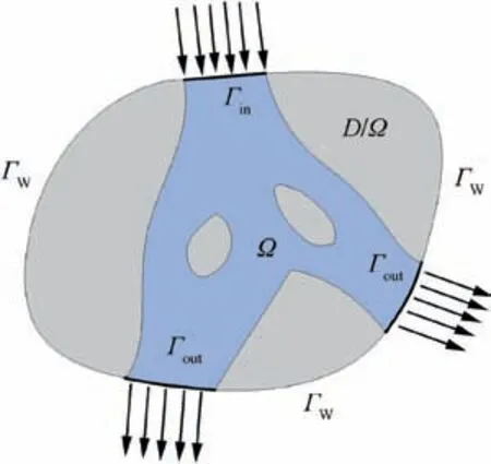
Fig. 1 Schematic figure of design domain D.
The physical model for the studied NCHS is a steady nanofluid based convective heat transfer problem which includes energy equations for solid domain and laminar continuity, momentum and energy equations for fluid domain. The model domains and boundary settings are shown in Fig. 1. Ω represents the fluid domain; ΓW, Γinand Γoutrespectively represent the wall boundary, inlet and outlet of the design domain. In the density method, a design variable, i.e. material density γ,is introduced to obtain the fluid/solid distribution in the optimization process.γ is distributed in the design domain with the value varying from zero to one continuously.γ=1 and γ=0 represent the fluid and solid materials respectively. The governing equations can be defined only in the fixed design domain D by using the design variable γ.
In the article, the coolant of NCHS is chosen as the water based Al2O3nanofluid. We adopt the widely used singlephase model to numerically study the flow and heat transfer of the nanofluid.Therefore,we assume the nanofluid is steady and the nanoparticle concentration is uniform. Under the assumption, the thermophysical properties of the nanofluid are not changed with the flow velocity and the fluid locations.
2.1. Thermophysical properties of the nanofluid
Based on the single-phase model,thermophysical properties of nanofluids have been extensively studied by both the experimental and theoretical approaches.49Here, we adopt the temperature-dependent properties of the nanofluid given by Khanafer and Vafai50which are verified by many experimental data and analytical studies. The international system of units(SI) is applied for the thermophysical properties. The nanofluid density(ρnf),specific heat capacity(cp,nf),dynamic viscosity (μnf) and thermal conductivity (knf) can be expressed as
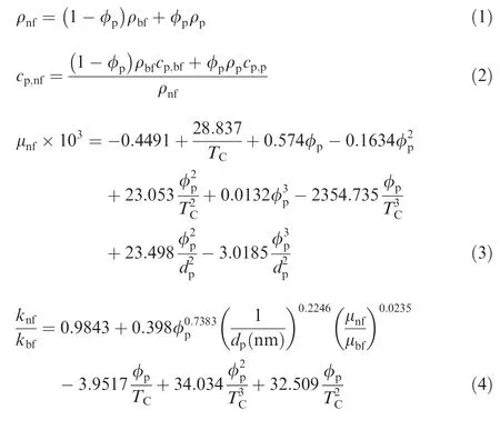
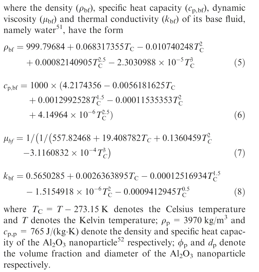
Fig. 2 shows the influence of the temperature TCon thermophysical properties for a typical nanofluid with φp=9%and dp=36 nm. We can see that the thermophysical properties, especially the important flow and heat transfer properties i.e.μnfand knf,strongly depend on the nanofluid temperature.Among them,the nanofluid dynamic viscosity value at 20°C is about three times larger than the value at 70°C. The large changes of thermophysical properties with temperature may affect the results of optimization design. So the temperaturedependent properties should be considered for the optimal design of NCHS. Unless otherwise stated, we adopt the temperature-dependent properties for the studied nanofluids throughout the paper.
2.2. Fluid field modeling
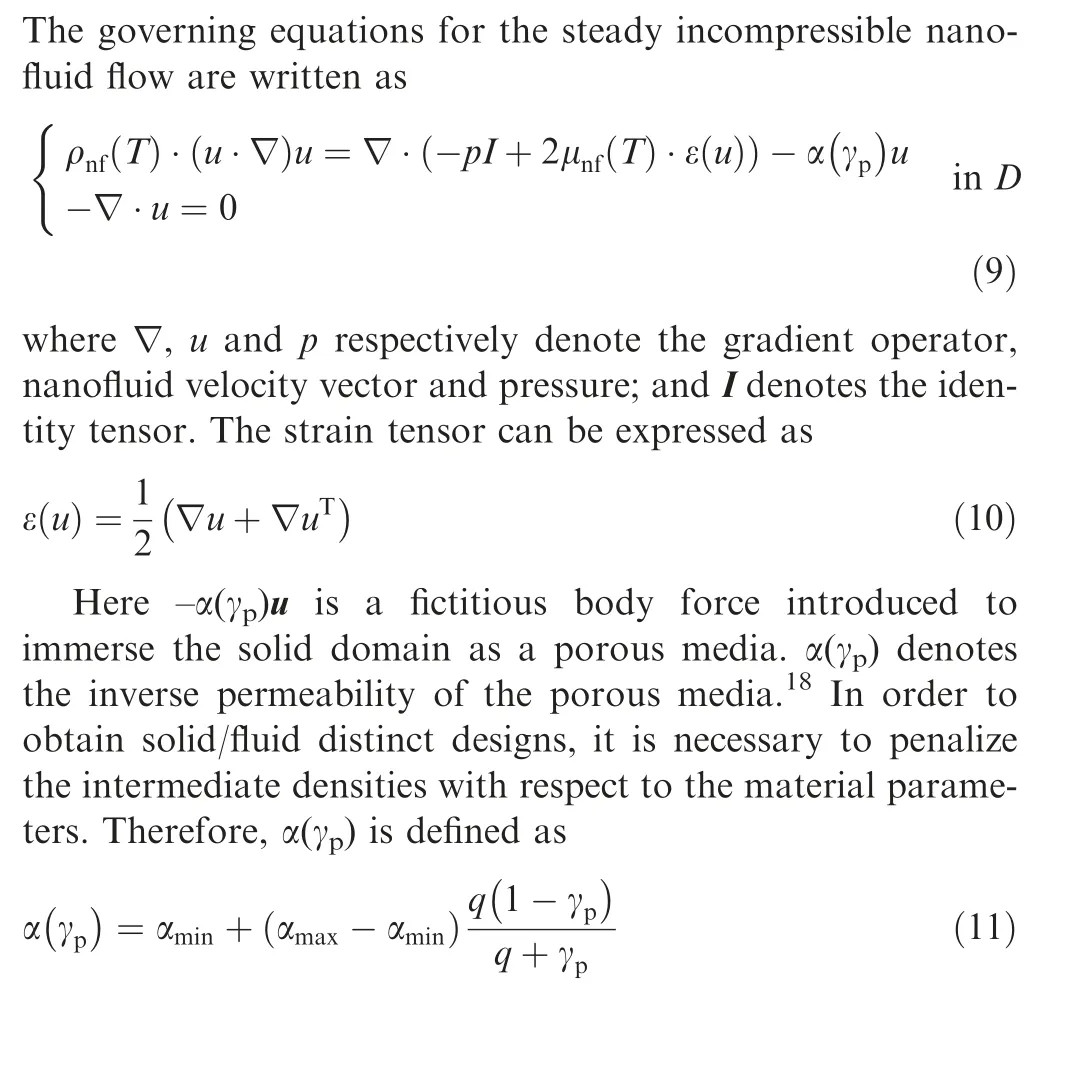
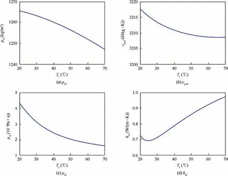
Fig. 2 Effect of temperature on thermophysical properties of nanofluid with φp=9% and dp=36 nm.
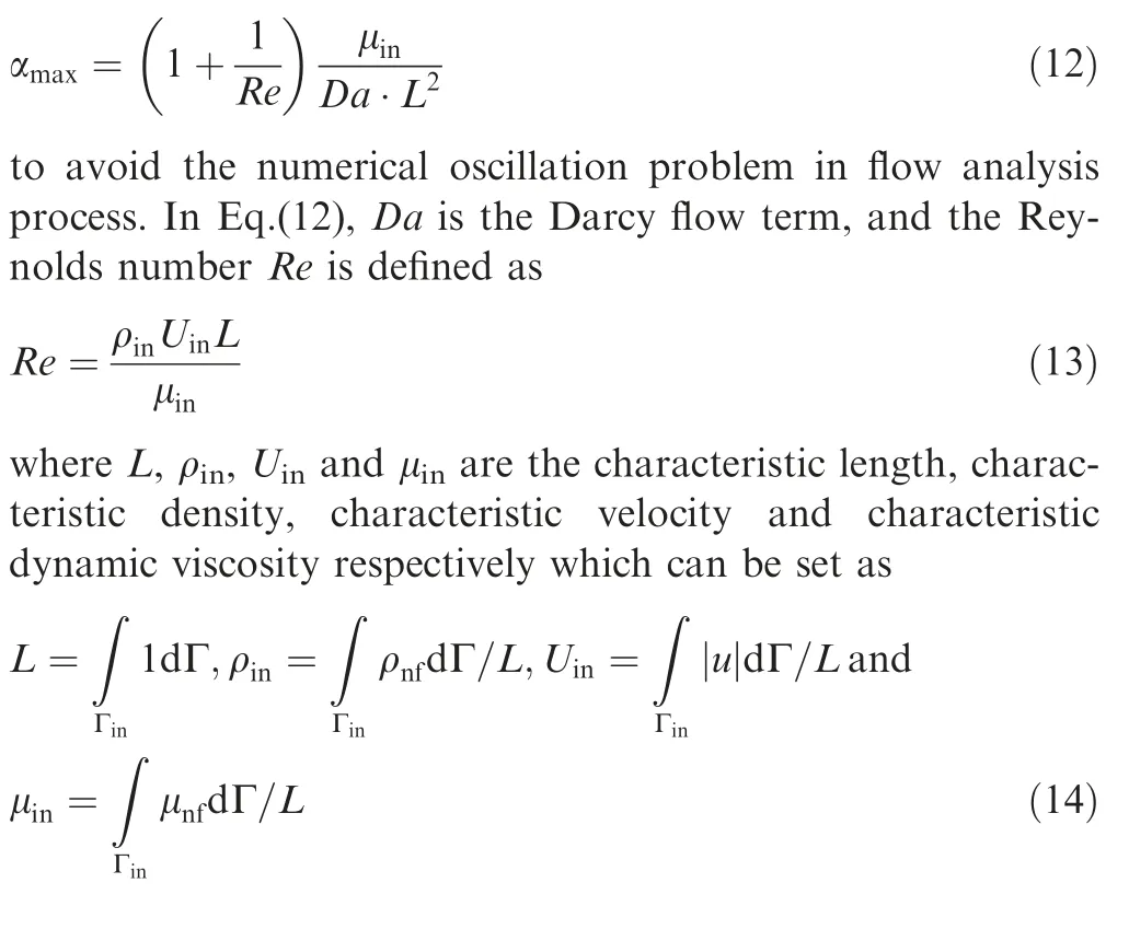
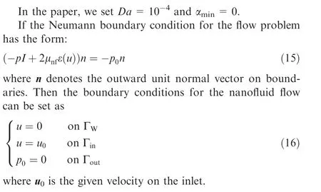
Which is the convex interpolation function proposed by Borrvall and Petersson.18q denotes a tuning parameter which can determine the convexity of the interpolation function for controlling the intermediate design variables. γpdenotes the regularized material density (see Section 3.1). αminand αmaxrespectively denote the inverse permeability in the fluid and solid domains. For the fluid domain (γp=1), the fictitious body force term –α(γp)u will vanish when we set αmin=0.For the solid domain (γp=0), we have α(γp)=αmax. The value of αmaxshould be defined as the infinite value to approximate the no-slip boundary condition at the fluid–solid interface. But αmaxis set to a large enough value53
2.3. Thermal field modeling
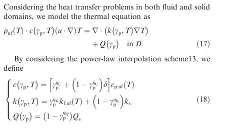
where ksdenotes the thermal conductivities of the solid,and Qsdenotes the heat generation per unit volume in the solid domain. The aluminum is applied as the solid material with ks=237 W/(m K).ηC,ηKand ηQare penalization power coefficients which can be used to penalize the intermediate densities. When γpis set to 1, Eq. (17) can become the convection heat transfer equation in the fluid domains. When both γpand δ are set to 0,Eq.(17)can be reduced to the heat conduction equation in the solid domains. Therefore, Eq. (17) can model the conjugate heat transfer problem in the whole design domain.In the study,δ is set as a sufficiently small positive real value, i.e. δ=10-15, to prevent numerical problems when solving Eq. (17).
The boundary conditions for the thermal field are defined as

3. Optimization model
3.1. Regularization
In order to reduce the complexity of the configuration, we adopt the Helmholtz filter method54to filter small-scale design features. The filtered design variable γfcan be obtained by solving the following equations

where r denotes the prescribed filter radius and ∂D denotes the boundary of the design domain D.We set r as the mesh size of the computed problem. But the density gradient may be smoothed and the fluid–solid interface may be blurred if the filter process is carried out individually.We introduce the hyperbolic tangent projection method proposed by Wang et al.55to cooperate the filter process by solving:

where γβ=0.5 denotes the projection threshold and β=4 denotes the projection slope. Then the crisp interface will be obtained.
3.2. Optimization problem
The basic optimization idea is to attain better heat transfer performance of NCHS by varying the design variable γ. We should first give the objective function to describe the heat transfer performance.For the 2D problem,the objective function is chosen to minimize the average temperature in solid domains which can be defined as

where f=(ux, uy, p, T) denotes the vector of state variables.For the 3D problem, the objective function is defined as the minimization of the average temperature in the fixed solid domain Ωpi.e.
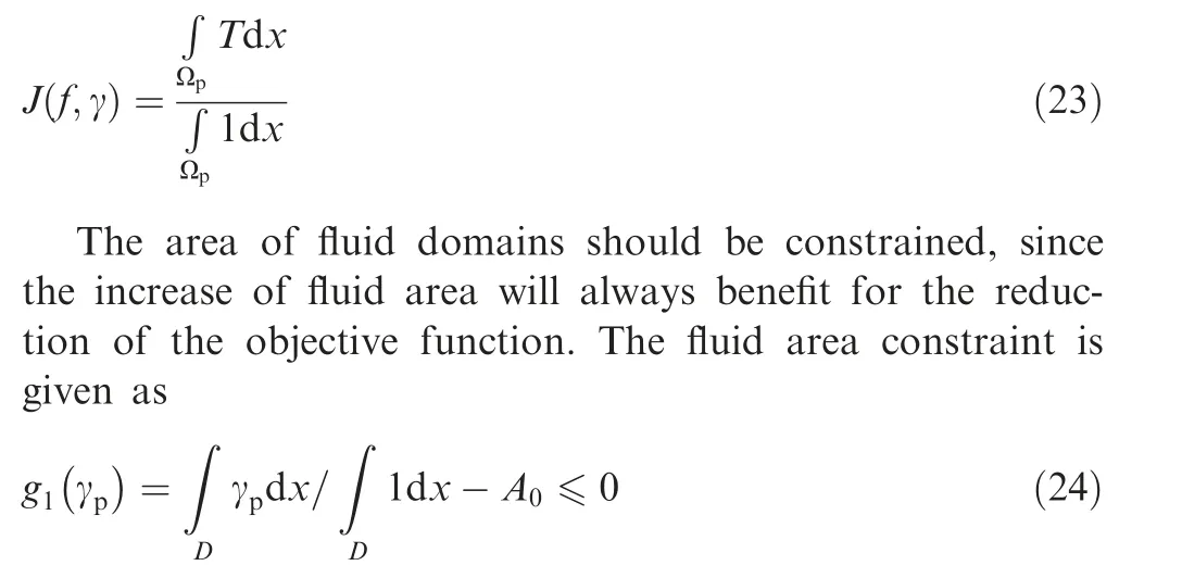
where A0is a given value for fluid fraction. We set A0=0.5 throughout the paper. For the optimization problem with velocity boundary conditions, the flow energy dissipation of the system should often be controlled to avoid the unreasonable design with extremely high pressure loss. The flow energy dissipation between the inlet and outlet boundaries is defined as
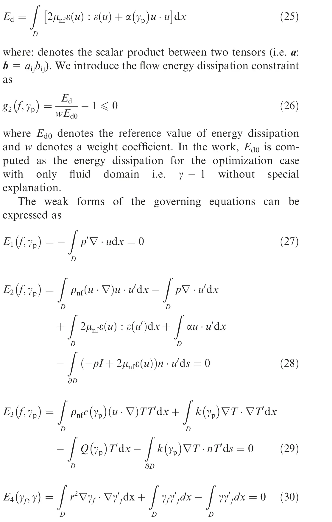
where γf′,p′,u′and T′are test functions of γf,p,u and T respectively. And we define
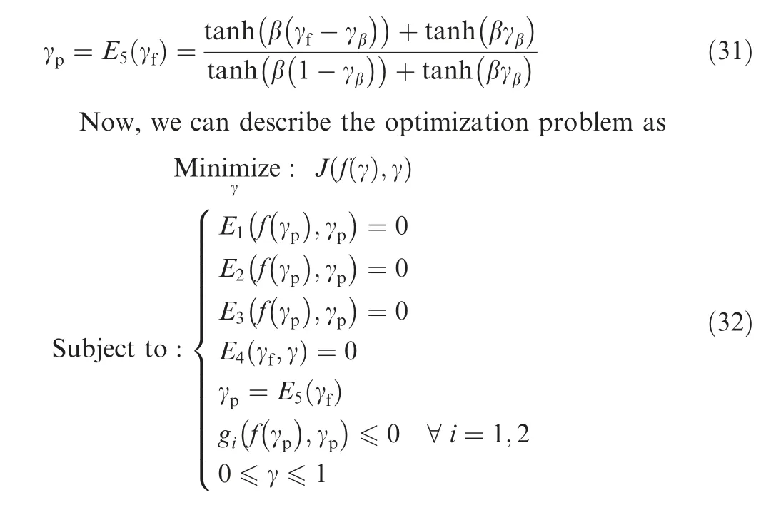
3.3. Sensitivity analysis
The convergence way of design variables is a fundamental problem in topology optimization. In this study, we adopt the gradient based algorithm to attain the updating of design variables.An adjoint based discrete sensitivity analysis method is utilized to obtain the gradient information for controlling the evolution direction of design variables, due to the large number of design variables in topology optimization.
First,we compute the Eulerian derivative of the objective J(f, γ) with respect to the design variable γpas
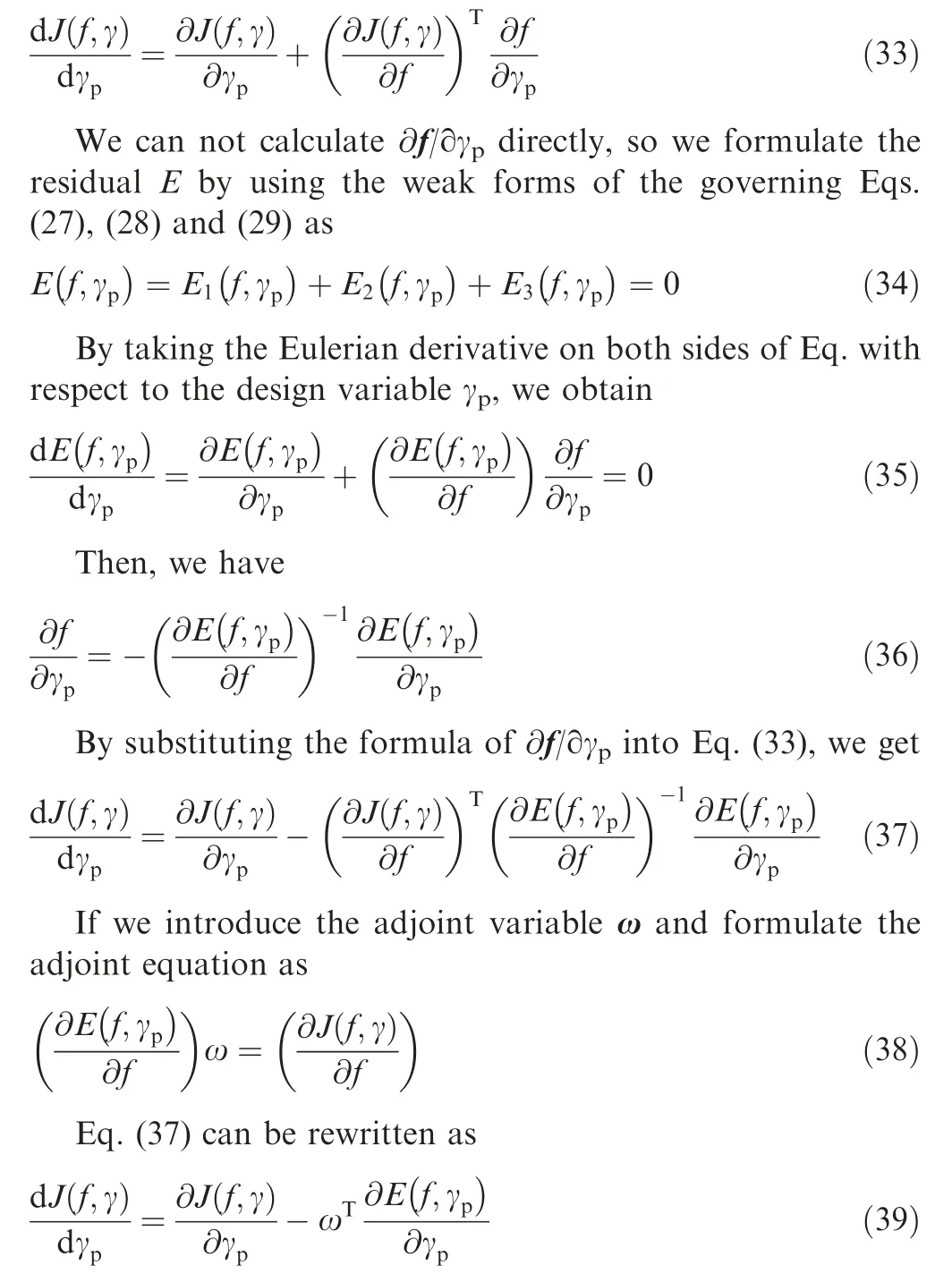
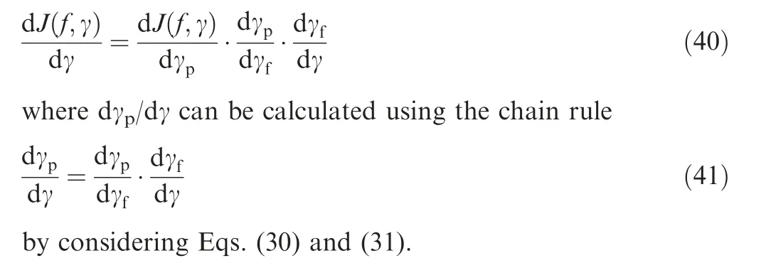
Therefore, the gradient information, i.e. dJ(f, γ)/dγ,for the studied optimization problem can be computed as
4. Numerical implementation
By considering temperature-dependent properties of the nanofluid,the Navier-Stokes equations(Eq.(9))depend on the state variables p, u and T. And the thermal equations (Eq. (17))depend on the state variables u and T. So the studied coupled flow and heat transfer problem is a two-way coupling problem.On the one hand,the flow velocity affects the heat transfer due to the convection. On the other hand, the temperature affects the flow due to the temperature-dependent density and dynamic viscosity. To obtain more accurate numerical result,we apply the fully coupled approach to solve Navier-Stokes equations (Eq. (9)) and thermal equations (Eq. (17))simultaneously.
We adopt a numerical iteration algorithm shown in Fig. 3 to implement the topology optimization on the platform of COMSOL Multiphyics (version 5.4).56The finite element method is applied to solve all the physical governing equations,adjoint equation and Helmholtz filter equation (Eq. (20)).
In the iteration process,we first initialize the design variable field γ, parameters and constants. Secondly, the physical governing equations, namely the Navier-Stokes equations (Eq.(9)) and thermal equations (Eq. (17)), are solved by the fully coupled approach to obtain the physical variables field f.Thirdly, the objective function (Eq. (22) or Eq. (23)) and constraints (Eq. (24) and Eq. (26)) are calculated. Fourthly, the convergence criterion is judged.If the convergence is achieved,the optimization process will be terminated. Otherwise, the iteration process will continue.Fifthly,obtain the adjoint variables field ω by solving the adjoint Eq.(38).Then,the gradient information dJ(f,γ)/dγ(see Eq.(40))is computed.Sixthly,the design variables field γ is updated by using the globally convergence method of moving asymptotes(GCMMA)57,58based on the computed sensitivities. Finally, regularize the design variables field γ utilizing the Helmholtz filter(Eq.(20))and hyperbolic tangent projection (Eq. (21)) methods.
5. Numerical results for 2D NCHS
In this section, we present numerical studies on 2D topology optimization of nanofluid based convective heat transfer problems. Firstly, effects of energy dissipation constraint on optimal configurations are discussed for different Reynolds numbers Re. Following this, effects of temperaturedependent fluid properties on optimized configurations are studied. Thirdly, effects of nanofluid characteristics on the optimized designs are investigated.
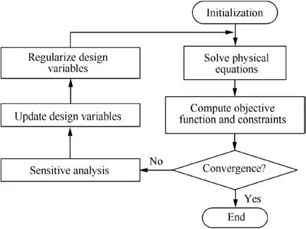
Fig. 3 Flow-chart of optimization procedure.
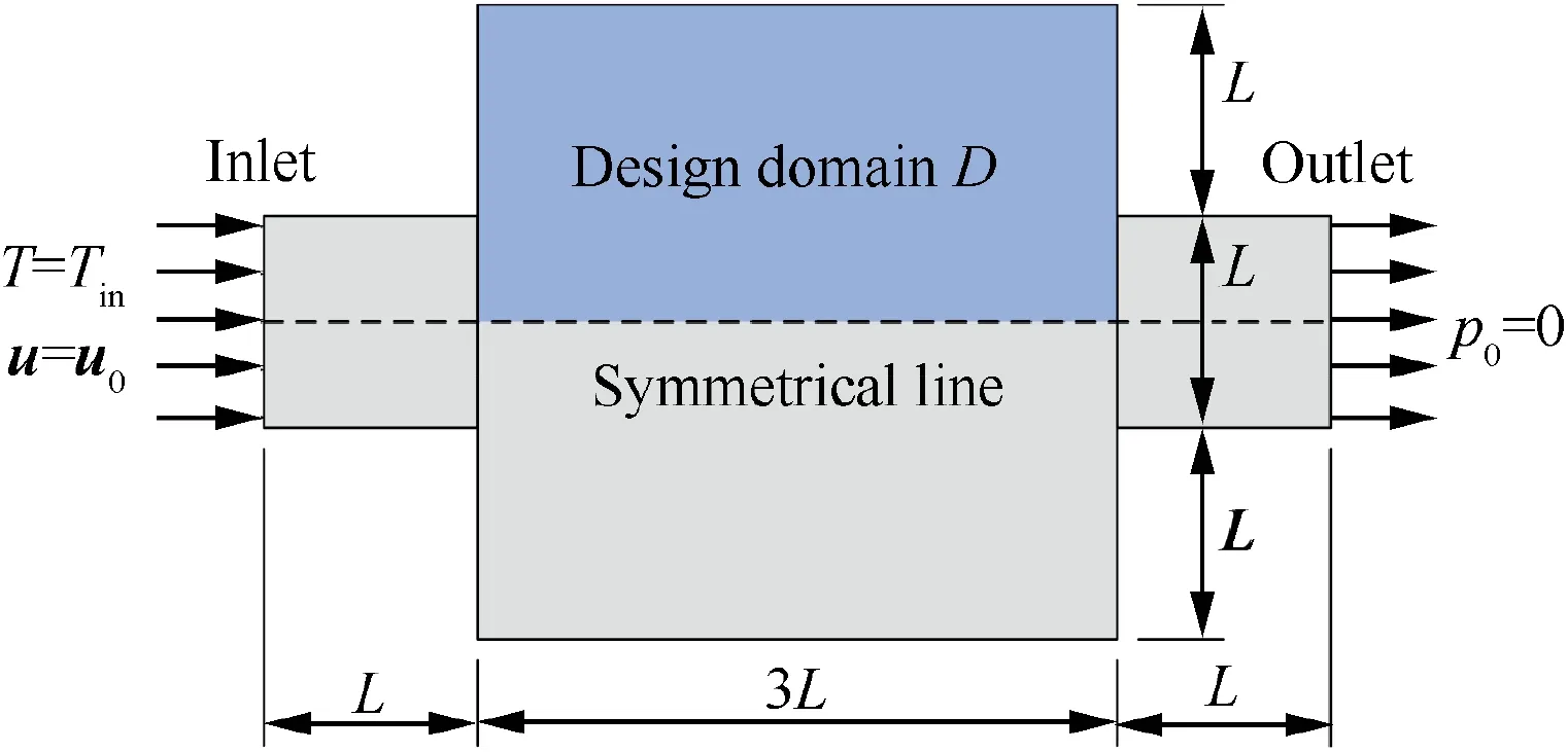
Fig. 4 Model domain and boundary conditions for 2D examples.
Fig. 4 shows the problem setup for 2D examples. The model domain is symmetrical where only half of it is considered in the optimization with the symmetrical boundary condition on the symmetrical line. Fully developed flow condition,p0=0 and no slip condition are set on the inlet, outlet and the wall boundary ΓWrespectively. The known temperature Tin=300 K is imposed on the inlet and zero gradient boundary condition is used on the outlet.We set the adiabatic condition on the wall boundary. The characteristic length is set as L=10-3m. The optimization domain is discretized with 8800 four-node quadratic elements. For all the 2D examples,we set the initial value of the design variable γ to 0.5.
From numerical tests, we find that the optimal configuration is sensitive to the choice of parameters q, ηC, ηKand ηQ.The parameters are initially set as q=0.01, ηC=1, ηK=1 and ηQ=1 to obtain more global solution. If there is serious intermediate density materials problem in the optimal configuration, these parameters can be increased in a step-wise manner to get more distinct fluid-solid interfaces.
5.1. Effects of the energy dissipation constraint on optimal configurations
Effects of the energy dissipation constraint on optimal designs are studied in this section. We set φp=9% and dp=36 nm for all cases. A constant heat source is used with Qs=106kW/m3. We first investigate topology optimization problems for different values of energy dissipation constraint when Re=50. Fig. 5 shows optimal configurations for increasing values of energy dissipation constraint. When the weight coefficient w is low,simple channels have been designed for the limit of the low energy dissipation.While the complexity of the branched flow channels rises as the allowed energy dissipation increases. So the heat exchange area is larger at the higher w case, which results in a better cooling performance. The objective values shown in Fig. 5 and temperature distributions shown in Fig. 6 evidence this conclusion. In Fig. 6, U denotes the velocity magnitude of optimal designs.But the objective value is not always increasing with the increase of w, since we can see from Fig. 5 that the change of objective value is little when w is above 100.
The optimization problems for the lower and higher Reynolds numbers are also studied. Optimal configurations and corresponding flow velocity and temperature distributions for Re=5 are shown in Figs. 7 and 8 respectively. Figs. 9 and 10 respectively display optimal designs and corresponding flow velocity and temperature distributions for Re=500.For both Re problems, we can obtain the similar conclusion as Re=50 that the increasing number of the branched flow channels at lager w cases may produce better cooling performances of optimal configurations. Besides, the cooling performances of optimal configurations for the higher Reynolds number cases are better than that for the lower cases.The reason for this is that more amount of heat might be taken away due to the higher flow rates at higher Reynolds number cases.
5.2.Effects of temperature-dependent fluid properties on optimal configurations
Effects of temperature-dependent fluid properties on optimal configurations are discussed in this section.The nanofluid with φp=9% and dp=36 nm is chosen as the coolant. The Reynolds number and heat source term are set as Re=50 and Qs=5×10⁶kW/m3respectively.We use the same energy dissipation constraint i.e. Ed0=5.51×10⁻⁴W/m and w=100 for all cases here.
Fig. 11 shows the optimal configuration and its flow velocity and temperature distributions with temperature-dependent nanofluid properties. For the comparison, three optimization cases with constant fluid thermophysical properties are conducted. The thermophysical properties for the constant problems are also computed by Eqs. (1)–(4) but with the constant temperatures, which are the minimum temperature i.e.T0=300 K, the average temperature of fluid domains i.e.T0=323.9 K and a higher temperature i.e. T0=340 K in Fig. 11 respectively. Values of T0and corresponding dynamic viscosity μnfare shown in Table 1. Fig. 12 shows the optimal configurations for the constant cases.Their corresponding flow velocity and temperature distributions shown in Fig. 13, and the objective and energy dissipation values shown in Table 2,are all computed with the temperature-dependent nanofluid properties.
The optimal configurations in Figs. 11 and 12 reveal that the number of flow channels for Design 2 is less than that for Design 1, but Design 3 and Design 4 have more complex flow channels than Design 1. More complex branched flow channels may increase the heat transfer area, which might enhance the cooling performance of NCHS. It is evidenced from Table 2 that the objective function is maximal for Design 2 and minimal for Design 4.However,more complex branched flow channels may also cause more serious energy dissipation,which can be verified by the changing trend of energy dissipation values shown in Table 2.
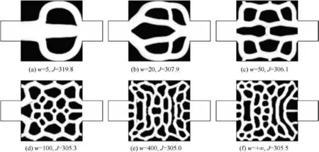
Fig. 5 Optimal configurations and corresponding objective values J for different values of weight coefficient w of energy dissipation constraint when Re=50.
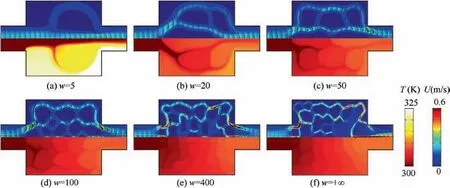
Fig.6 Flow velocity(upper half)and temperature(lower half)distributions for optimal configurations with respect to different values of weight coefficient w when Re=50.

Fig. 7 Optimal configurations and corresponding objective values J for different values of weight coefficient w of energy dissipation constraint when Re=5.

Fig.8 Flow velocity(upper half)and temperature(lower half)distributions for optimal configurations with respect to different values of weight coefficient w when Re=5.

Fig. 9 Optimal configurations and corresponding objective values J for different values of weight coefficient w of energy dissipation constraint when Re=500.

Fig.10 Flow velocity(upper half)and temperature(lower half)distributions for optimal configurations with respect to different values of weight coefficient w when Re=500.

Fig. 11 Optimal configuration, and corresponding flow velocity and temperature distributions with temperature-dependent fluid properties when Re=50 and Qs=5×10⁶ kW/m3.

Table 1 Values of T0 and dynamic viscosity μnf for optimization cases with constant fluid properties.
In addition,Design 2 has slightly straighter branched channels and wider flow outlet when compared with Design 1.From the velocity distributions in Figs. 11 and 13, we can see that Design 2 has smoother flow and more uniform velocity than Design 1. These phenomena may indicate the lower energy dissipation of Design 2. While Design 3 and Design 4 have more twisted flow channels and narrower flow outlet than Design 1.These design features may worsen the smoothness of the flow, which may lead to higher energy dissipations.
It can be observed from Table 2 that only the objective value for Design 4 is higher than that for Design 1 and values for the other two designs is lower. But the energy dissipation values for Design 3 and Design 4 are much higher than the constraint value i.e. 0.055 W/m. Therefore, the temperaturedependent result has best cooling performance among the designs fulfilling the constraints.
It should be noted that,all the optimal configurations fulfill the given energy dissipation constraint in their calculation frameworks,where the thermophysical properties are different from each other.From above discuss,we know that the energy dissipation constraint is strongly related with the design result.Since the energy dissipation directly relates with the nanofluid dynamic viscosity μnf(see Eq. (25)), we may deduce that the viscosity differences between the optimization cases might be the main reason for the different optimal results. We can see from Table 1 that the dynamic viscosity μnfrises with the increase of T0. For the higher μnfproblem, we know from Eq. (25) that the required velocity gradient may be lower to reduce the strain tensor due to the same energy dissipation constraint. So the optimal design has straighter branched channels and wider flow outlet to obtain lower velocity gradient, which indicates that μnfmight be the main reason for design features of the optimal configuration.
5.3. Effects of nanofluid features on optimal configurations
In the section, we first study effects of the volume fraction φpand diameter dpof the Al2O3nanoparticle on optimal configurations respectively. And then topology optimization problem of nanofluids’ base fluid is investigated and its result is compared with those of the nanofluids. We set Re=50,Qs=106 kW/m3, Ed0=5.51×10⁻⁶W/m and w=100 for all cases.

Fig. 12 Optimal configurations with constant thermophysical properties.

Fig. 13 Flow velocity (upper half) and temperature (lower half) distributions for optimal configurations shown in Fig. 12.

Table 2 Values of objective function J and energy dissipation Ed for optimal configurations in Figs. 11 and 12.
5.3.1.Effects of nanoparticle diameter on optimal configurations
We first fix the value of nanoparticle volume fraction as φp=7% and investigate effects of nanoparticle diameter dpon optimal configurations. Fig. 14 shows optimal configurations for several typical nanoparticle diameters. We can see that the complexities of the branched flow channels are similar,which may indicate the similar heat transfer areas between the optimal configurations.While it can be observed from Table 3 that the flow rate φvdecreases caused by the decline of μinwith the increase of dp,since Re is a fixed value,ρinis not the function of dp(see Eq. (1) and (14)) and φvcan be computed as

by considering Eq.(13).The decrease of flow rate might reduce the amount of heat taken away from the outlet, which may lead to the decline of heat transfer performance. The decrease of the cooling performance is evident from the objective values in Table 3 and the temperature distributions in Fig. 15.
Besides, if we define characteristic thermal conductivity kinas the average thermal conductivity at the inlet with the form:

we can see the decrease of kinin Table 3. The decreased thermal conductivity may also indicate the reduced cooling performance of optimal configurations.
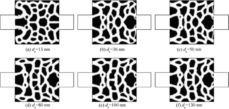
Fig. 14 Optimal configurations for different values of nanoparticle diameter dp.

Table 3 Values of objective function J,characteristic dynamic viscosity μin,flow rate φv and characteristic thermal conductivity kin for optimal configurations with different values of nanoparticle diameter dp.
5.3.2. Effects of nanoparticle volume fraction on optimal configurations
Effects of nanoparticle volume fraction φpon optimal designs are studied with dp=36 nm.Figs.16 and 17 respectively show optimal configurations and the corresponding flow velocity and temperature distributions for several typical nanoparticle volume fractions. The corresponding values of the objective function J, characteristic dynamic viscosity μin, characteristic density ρin, flow rate φvand characteristic thermal conductivity kinare shown in Table 4. From Table 4, we can see that μinexperiences large increase, while ρinexperiences slight increase with the increase of φp. According to Eq. (42)the flow rate φvincreases with the rise of φp, which can also be observed from Table 4. So more fluid can be used to bring more amount of heat away from the hot solid domains,which may be the main reason for the enhancement of cooling performances. The increase of cooling performances can be testified by the objective values shown in Table 4 and temperature distributions shown in Fig. 17. In addition, it can be observed from Table 4 that the characteristic thermal conductivity kinincreases with φp.The rise of kinwould enhance the heat transfer ability of the nanofluid to a certain extent, which may be another reason for the advance of cooling performances.
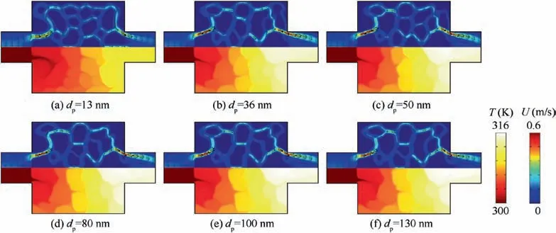
Fig.15 Flow velocity(upper half)and temperature(lower half)distributions for optimal configurations with respect to different values of nanoparticle diameter dp.
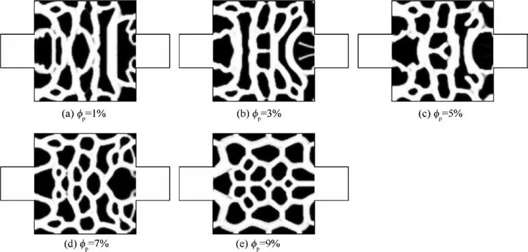
Fig. 16 Optimal configurations for different values of volume fraction φp.
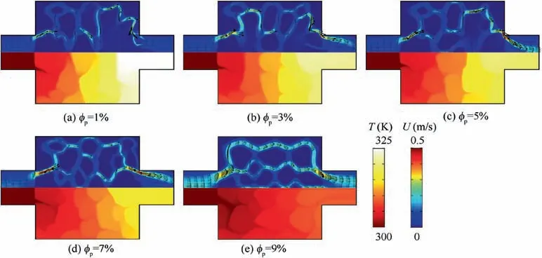
Fig.17 Flow velocity(upper half)and temperature(lower half)distributions for optimal configurations with respect to different values of the volume fraction φp.

Table 4 Values of objective function J,characteristic dynamic viscosity μin,characteristic density ρin,flow rate φv and characteristic thermal conductivity kin for optimal configurations with different values of the nanoparticle volume fraction φp.
From Fig.16,we can see that the widths of flow channels at the inlet/outlet increase with φp, and the flow channels more direct from the inlet to the outlet at higher φpcase. The increases of both μinand φvwould make the flow smoother and the velocity more uniform as shown in Fig. 17. This phenomenon may be explained as the optimal design with higher μinmay allow lower velocity gradient according to Eq. (25)when the same energy dissipation constraint is used.
5.3.3. Topology optimization for nanofluid’s base fluid
To study the effects of nanofluid characteristics on optimal configurations comprehensively, we conducted topology optimization for nanofluid’s base fluid. The optimization can be achieved simply by replacing temperature-dependent properties of the nanofluid(i.e.ρnf,cp,nf,μnfand knf)by those of the base fluid(i.e.ρbf,cp,bf,μbfand kbf).Fig.18 shows the optimal configuration and the corresponding flow velocity and temperature distributions.The flow and heat transfer features for the optimal design are shown in Table 5. By comparing the result in Table 5 with those in Table 3 and Table 4, we can see that the value of flow rate φvfor the base fluid is lower than the values for nanofluids, which may be caused by the lower μinfor the base fluid. The lower flow rate would be the main reason for the lower heat transfer performance of the base fluid.The lower flow rate may also lead to the unsmooth flow channels of the optimal design in Fig. 18. In addition, the lower value of kinin Table 5 may also reduce the heat transfer ability of the base fluid.Therefore,it can be observed from the objective values shown in Table 3,Table 4 and Table 5 and temperature distributions shown in Figs. 15, 18 and 19 that the cooling performance of the optimal configuration for the base fluid is worse than those of nanofluids.

Fig. 18 Optimization result for base fluid with optimal configuration and its flow velocity (upper half) and temperature (lower half)distributions.

Table 5 Flow and heat transfer features for optimal configuration shown in Fig. 18.
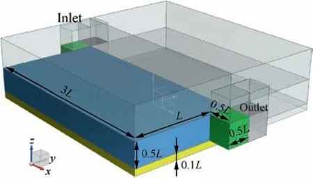
Fig. 19 Computational domain for the 3D problem.
6. Numerical results for 3D NCHS
A numerical example of 3D topology optimization of the nanofluid based convective heat transfer problem is investigated. The effect of temperature-dependent fluid properties on optimal configurations is discussed here. The setup for the 3D problem is shown in Fig. 19. A quarter of the domain is used for the optimization since the symmetry in both y and z directions are taken into account. Yellow color represents the fixed solid domain Ωp(heated plate),green color represents the fixed fluid domain for inlet and outlet, and blue color represents the design domain. Fully developed flow condition and p0=0 are imposed on the inlet and outlet respectively.No slip flow conditions are set on the other boundaries.The given temperature Tin=300 K and zero gradient boundary condition are imposed on inlet and outlet respectively. Different from the 2D problem, there is no heat source term here that is Qs=0 kW/m3. As an alternative, heat is transferred from the top and bottom boundaries of thin plates which are fixed solid domains in the optimization process.The following Neumann boundary condition is imposed on top and bottom boundaries:

where the heat flux is set to Q0=1000 kW/m2.Adiabatic condition is set on the all other boundaries. For the 3D example,we also set γ=0.5 and L=10-3m. The nanofluid with φp=9% and dp=36 nm is used as the coolant. The optimization domain consists of 55,292 hex elements. The optimization process is performed on Intel Core i7-8700 CPU(3.20 GHz) cores. The penalization parameters are used as q=0.01, ηC=1, ηK=1 and ηQ=1. The objective function for the 3D problem is to minimize the average temperature in the heated plate Ωp.The energy dissipation constraint is set as Ed0=2.01×10⁻⁷W and w=30 for all cases.
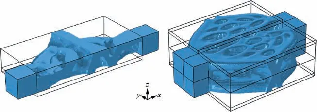
Fig. 20 Optimal configuration (fluid domain) with temperature-dependent thermophysical properties for the 3D example (Design 5).

Fig. 21 Flow velocity magnitude and temperature distributions for temperature-dependent result in Fig. 20.
Figs. 20 and 21 show the optimal fluid domain for the temperature-dependent problem, and its flow velocity magnitude and temperature distributions respectively.The computational time for the problem is around 61 hours. From Fig.20,we can see that the configuration in the z direction is different.More flow channels are arranged close to the heated plates in order to accelerate convective heat transfer between the cold nanofluid and the hot plates. Several optimization cases for the coolant with constant thermophysical properties are conducted. Fig. 22 shows optimal fluid domains corresponding to the nanofluid properties at T0=300 K, T0=321.9 K and T0=340 K, which are the lower, average and higher temperatures of the fluid domains in Fig.21(b)respectively.Values of T0and the corresponding CPU time and dynamic viscosity μnffor the constant cases are shown in Table 6. The flow velocity magnitude and temperature distributions shown in Figs. 23 and 24,and the objective and energy dissipation values shown in Table 7 for the constant optimal configurations are all computed with the temperature-dependent nanofluid properties.
It can be observed from Figs.20 and 22 that the flow channels for Design 5 are more complex than those for Design 6,but simpler than the ones for Design 7 and Design 8.Complex channels may provide larger contact surface area close to the heated plates which might enhance the heat transfer between the hot plates and the cold coolant. This explains the better cooling performances of Design 7 and Design 8, and worse performances of Design 6 (see Table 7).

Table 6 Values of T0,CPU time and dynamic viscosity μnf for optimization cases with constant thermophysical properties.
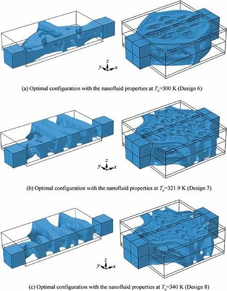
Fig. 22 Optimal configurations (fluid domains) with constant thermophysical properties for the 3D problem.
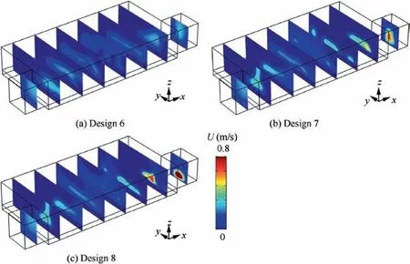
Fig. 23 Flow velocity magnitude distributions for optimal configurations shown in Fig. 22.
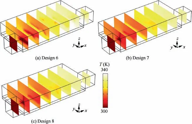
Fig. 24 Temperature distributions for optimal configurations shown in Fig. 22.

Table 7 Values of objective function J and energy dissipation Ed for optimal configurations in Figs. 20 and 22.
The differences of optimal configurations are caused by the different thermophysical properties of coolants, among which the dynamic viscosity may play an important role. From Eq.(25) we know that the coolant with higher dynamic viscosity μnfmay allow lower velocity gradient in the optimization process if the energy dissipation is same. So the higher μnfmay limit the complexity of the optimal configuration to reduce the velocity gradient under the same energy dissipation constraint.From Table 6,Figs.21 and 23,we can see that the lower velocity gradient appears in the higher μnfcase. However,the complex configuration may cause high energy dissipation when computed with the same temperature-dependent nanofluid properties. It can be observed from Table 7 that the energy dissipation values for Design 7 and Design 8 are much higher than the constraint value.Although Design 6 satisfies the energy dissipation constraint,its cooling performance is lower than Design 5’s. Therefore, the optimal configuration of the temperature-dependent case has the best heat transfer performance among the designs fulfilling the design requirements. In other words, optimal configurations with constant thermophysical properties either do not satisfy the constraint,or have poor cooling performances.
7. Conclusions
The article conducted topology optimization design of NCHS by using a density based method.Effects of the energy dissipation constraint, temperature-dependent fluid properties and nanofluid characteristics on optimal configurations were discussed. The obtained conclusions were presented as follows.
(1) The water based Al2O3 nanofluid was adopted as the coolant of NCHS. We treated it as a single-phase fluid with the temperature-dependent properties due to the strong temperature-dependent characteristics of nanofluids.The material interpolation method was used to model the governing equations in the fixed design domain. The average temperature in solid domains was minimized subject to fluid area and energy dissipation constraints.
(2) The design variables γ were updated by using GCMMA according to the gradient information obtained by an adjoint based sensitivity analysis method. The Helmholtz filter and the hyperbolic tangent projection methods were applied to regularize γ respectively.
(3) In numerical examples,effects of energy dissipation constraint on optimal designs were first discussed with several 2D optimization cases. The numerical results indicated that both the complexity of the branched flow channels and the cooling performance of the optimal design rose as the increase of allowed energy dissipation.
In addition, effects of temperature-dependent fluid properties on optimized configurations were studied with both 2D and 3D examples.The optimization results revealed that there were significant differences between optimal configurations for the temperature-dependent case and constant ones. The fluid dynamic viscosity might be the main reason for the design differences. The temperature-dependent result had best cooling performance among the designs fulfilling the constraints.
Then, we respectively investigated the effects of nanoparticle volume fraction φpand diameter dpon optimized configurations with the 2D examples. The results demonstrated that the heat transfer performances of optimal configurations increased with the decrease of the nanoparticle diameter dpor the increase of the nanoparticle volume fraction φp.
Finally,topology optimization for the base fluid of nanofluids was conducted.The results showed that the cooling performance of the optimal configuration for nanofluids was better than that of its base fluid.
Acknowledgement
The authors are grateful to Professor X.-P Chen for helpful discussions.B.Z.is supported by the National Natural Science Foundation of China (No. 51905435) and Fundamental Research Funds for the Central Universities (No.G2018KY0306). L.G. is supported by the National Natural Science Foundation of China (No. 51790512).
 CHINESE JOURNAL OF AERONAUTICS2021年2期
- CHINESE JOURNAL OF AERONAUTICS的其它文章
- Recent active thermal management technologies for the development of energy-optimized aerospace vehicles in China
- Electrochemical machining of complex components of aero-engines: Developments, trends, and technological advances
- Recent progress of residual stress measurement methods: A review
- Micromanufacturing technologies of compact heat exchangers for hypersonic precooled airbreathing propulsion: A review
- Towards intelligent design optimization: Progress and challenge of design optimization theories and technologies for plastic forming
- A combined technique of Kalman filter, artificial neural network and fuzzy logic for gas turbines and signal fault isolation
