Grinding force and surface quality in creep feed profile grinding of turbine blade root of nickel-based superalloy with microcrystalline alumina abrasive wheels
Qing MIAO, Wenfeng DING, Weijie KUANG, Changyong YANG
National Key Laboratory of Science and Technology on Helicopter Transmission, Nanjing University of Aeronautics and Astronautics, Nanjing 210016, China
KEYWORDS Creep feed profile grinding;Fir-tree blade root;Grinding force;Single crystal nickel-based superalloy;Surface quality
Abstract Creep feed profile grinding of the fir-tree blade root forms of single crystal nickel-based superalloy was conducted using microcrystalline alumina abrasive wheels in the present study.The grinding force and the surface quality in terms of surface topography, subsurface microstructure,microhardness and residual stress obtained under different grinding conditions were evaluated comparatively.Experimental results indicated that the grinding force was influenced significantly by the competing predominance between the grinding parameters and the cross-sectional root workpiece profile.In addition,the root workpiece surface,including the root peak and valley regions,was produced with the large difference in surface quality due to the nonuniform grinding loads along the root workpiece profile in normal section. Detailed results showed that the surface roughness, subsurface plastic deformation and work hardening level of the root valley region were higher by up to 25%,20%and 7%in average than those obtained in the root peak region,respectively,in the current investigation. Finally, the superior parameters were recommended in the creep feed profile grinding of the fir-tree blade root forms.This study is helpful to provide industry guidance to optimize the machining process for the high-valued parts with complicated profiles.
1. Introduction
The detachable rotating turbine blades are employed by the majority of advanced aero-engines, and they are usually mounted onto a series of rotor disks by using the fir-tree blade root forms (Fig. 1).1,2Due to the strict environment of application,the turbine blade roots are generally fabricated by various nickel-based superalloys and titanium alloys because of their high strength, high wear and corrosion resistance at elevated temperatures.3–5These excellent properties, however,throw great challenges for the efficient and cost-effective machining. In addition, such materials are usually difficult to cut as demonstrated by the large cutting forces, high tooling wear,low machining quality and relatively long manufacturing times,like in the broaching and milling processes for the blade root manufacture.6–13To overcome these problems,creep feed grinding(CFG)is introduced,involving the use of large grinding depth, slow workpiece speed, flexible machining centers equipped with highly porous conventional abrasive wheels,high pressure fluid delivery system, and semicontinuous dressing.2The large grinding depth of CFG is also well preferred due to the large stock allowances of the turbine blade root workpiece.
Therefore, CFG associated with conventional abrasive wheels becomes the traditional grinding strategy for machining the fir-tree blade root forms.However,a practical result found in previous tests is that the rapid rate of wheel wear and low ability to maintain the dimensional accuracy are always the bottleneck for conventional abrasive wheels to reach a desired grinding efficiency.14Increasing the dressing frequency tends to solve these practical problems, while the tool service life has to be greatly shortened. For this reason, the superhard abrasive wheels, e.g. CBN wheels, are proposed to use for machining the fir-tree blade root. Nevertheless, the high cost and the low potential with regard to the dressing capability are the generally major problems for superhard abrasive wheels to profile grinding,15,16even though it is demonstrated that the active surfaces of superhard abrasive wheel can be specially-designed and textured,17,18and are capable of creep feed grinding deep fir-tree slots and fir-tree root forms on the difficult-to-cut nickel-based superalloys with free workpiece burning.2,19–21On the contrary, due to the low hardness and cost-effective price compared to the superhard abrasive wheels,conventional abrasive wheels are evidenced with an excellent profiling ability and become widely applied in the turbine blade root manufacture. For instance, Poklad22used different alumina abrasive wheels for creep feed grinding the fir-tree blade root forms. High surface quality, e.g.the surface roughness of 0.65 μm and the compressive stress of up to 490 MPa,was achieved. Guo et al.23,24developed the process to realize the continuous dressing creep feed profile grinding of the firtree blade root forms using conventional abrasive wheels.Control of the blade root grinding process was further optimized by monitoring the power signature and adjusting the dress infeed rate and workpiece speed to improve the grinding efficiency. The consequences in above tests indicate that the relatively short service life of conventional abrasive wheels can be offset by the high profiling ability and acceptable surface quality.
In addition, the newly developed microcrystalline alumina abrasive wheels have the higher potential for profile grinding as evidenced by the large grinding ratios, high MRRs, low grinding forces, low geometrical wear, and good ground surface integrity, compared to the conventional abrasive wheels.25-29This type of grinding wheel is therefore very suitable for creep feed profile grinding blade root forms though further investigations have to be done to optimize the process results.
To this end, an experimental study for developing the process to creep feed profile grinding the fir-tree blade root forms of single crystal nickel-based superalloy using microcrystalline alumina abrasive wheels was carried out. In particular, only single sided root form was ground and considered throughout the present work for simplicity.The grinding force and surface quality (including the surface topography, subsurface microstructure, microhardness and residual stress) generated under different combinations of grinding parameters were evaluated comparatively. The present investigation can provide a deep understanding and useful guidance for creep feed grinding the high-valued parts with fir-tree forms in production.
2. Experimental procedure
Fig. 2 shows the experimental setup for creep feed profile grinding.All the grinding tests were conducted on the Profimat MT-408 grinding center (Blohm, Germany) with a maximum spindle speed of 8000 r/min and power rating of 45 kW. High pressure pumping system(up to 1.5 MPa with the flow rate of 45 L/min) was utilized to cool the grinding zone via the laminar flow nozzle using 5% water based emulsion. Rectangular blocks of single crystal nickel-based superalloy with the dimensions of 32 mm×15 mm×12 mm were employed as the workpiece materials.Detail properties on this workpiece material are shown in Table 1.28,30The workpiece was clamped by the jig which was mounted on the machine worktable (Fig. 2(c)). The microcrystalline alumina abrasive wheels(400 mm×20 mm×127 mm, 5SG80F45V, Sisha Co., Ltd.China) which had the vitrified bond, open structure and mesh size of 80# were used as the grinding tools.
The full experimental process consisted of 2 grinding cases involving variations in wheel speed vs, workpiece speed vw,grinding depth apand accumulated grinding depth h. The accumulated grinding depth h was the distance that the wheel moved in the vertical direction, as schematically shown in Fig. 3. The total stock allowance of the blade root workpiece was designed as 2.63 mm in the current study. All tests were performed in an up grinding creep feed model without spark-out. The experimental arrangements are displayed in Table 2. Each grinding case involved 6 grinding passes on the workpiece.After each grinding pass,dressing of the wheels was performed by using the diamond roller dresser with the diameter of 152.1 mm and the mesh size of 45#, as shown in Fig. 2(b), under the following conditions: dressing speed 20 m/s, dressing speed ratio -0.7, dressing infeed rate 1.3 mm/min, and total dressing amount 0.2 mm.
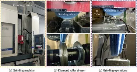
Fig. 2 Experimental setups.

Table 1 Chemical compositions, heat treatments and mechanical properties of single crystal nickel-based superalloy used in study.28,30
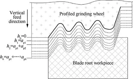
Fig. 3 Schematic diagram of the profile grinding process in the vertical direction.
In the creep feed profile grinding process,the grinding force components were measured by the three-component dynamometer modeled HR-FP3407 (H&T Horizon). After grinding, the residual stresses of selected regions on the blade root specimen were firstly measured using the X-ray method by means of a MG2000L goniometer with Mn Kα radiation(LXRD micro-area, Proto, Canada). Two measurements were recorded in one selected region and the results were averaged.Secondly, the surface topography of the specimen was examined by the scanning electron microscope (SEM) (Hitachi S3400, Japan) and then cut perpendicular to the grinding direction.Thirdly,the specimen was polished to achieve a surface roughness of below 0.1 μm,followed by etching for about 30 s using a special reagent (25 mL HNO3+25 mL H2O+50 mL HCl). Finally, the subsurface microstructural examination was conducted with an optical microscope(OM)(Leica DM3000, Germany) and the above-mentioned SEM. In addition, the microhardness evaluation was undertaken with an HXS-1000AK hardness tester using the Vickers indenter at a load of 25 g applied for 15 s.
3. Results and discussion
3.1. Grinding forces
Fig. 4 shows the changes of the grinding force components,including the tangential grinding force Ftand the normal grinding force Fn, as the accumulated grinding depth h increased in the creep feed profile grinding process. It can be observed that, based on the results of grinding case I, as h increased from 1.5 (grinding pass No.1) to 4.13 mm (grinding pass No.4), the grinding force components, i.e., Ftand Fn,increased remarkably from 118.8 to 238.4 N and from 287.5 to 572.9 N, respectively. But the grinding forces changed slightly if h further increased to 5.26 mm (grinding pass No.6) compared to those results obtained when h was 2.63 mm(grinding pass No.3).It was also found in Fig.4 that,Ftand Fnincreased from 118.8 to 144.1 N and from 287.5 to 424.5 N respectively,when h increased from 1.5(grinding pass No.1) to 2.5 mm (grinding pass No.2), while they tended to decrease from 238.4 to 145.2 N and from 572.9 to 361.5 N respectively, when h increased from 4.13 (grinding pass No.4) to 5.13 mm (grinding pass No.5). The common characteristic between the grinding passes No.1 and No.4, No.2 and No.5, No.3 and No.6, respectively, was the same grinding parameters that used in the root forms grinding process(Table 2). However, the changes of corresponding grinding forces were different.Similar trends were found in the grindingcase II.The grinding forces measured based on grinding case II were inevitably larger than those obtained in the grinding case I due to the bigger workpiece speeds used in grinding. These facts indicate that the forces were highly dependent on not only the grinding parameters, but also the accumulated grinding depth in the profile grinding process.
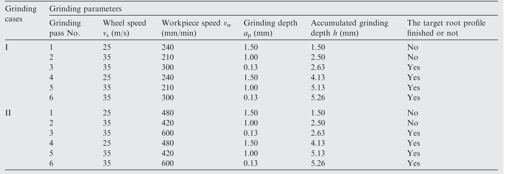
Table 2 Experimental arrangement.
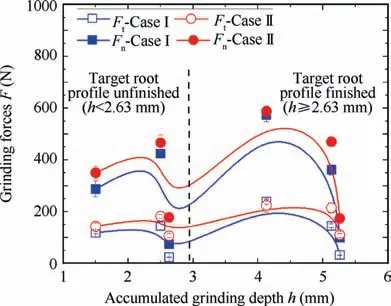
Fig. 4 Effect of accumulated grinding depth on changes of grinding force components.
Workpiece material removal and surface integrity are produced within the wheel-workpiece contact zone during grinding. The wheel-workpiece contact area is therefore an important determinant in the grinding process. In addition,the grinding forces are strongly influenced by the undeformed chip thickness which dominants the workpiece material removal process in the contact zone.31–33To further understand the relationship between the grinding forces, root profiles and the grinding parameters, the changes of grinding force with increasing wheel-workpiece contact area are shown in Fig. 5. Particularly, the contact area S was calculated according to the profile changes of root workpiece (Fig. 3)and can be expressed as follows34:

where l is the profile length of root workpiece in grinding and dsis wheel diameter.It can be found in Fig.5 that regardless of which case of grinding parameters was used, the wheelworkpiece contact area had generally the positive effects on the increasing grinding force due to the increased numbers of active abrasive grains involved in cutting. In addition,the factors that resulted in the changes of contact area and further affected the grinding force can be analyzed as follows:
(i) Assuming that the wheel diameter remained constant,Eq.(1)shows that if the root profile length l or the grinding depth apwas decreased,the wheel-workpiece contact area S could be reduced. Apparently, when h=2.63 mm or h=5.26 mm, the profile of root workpiece was very close to the target one and would be great similar (Table 2). At this moment, the small value of approduced the small contact area S (around 120 mm2)and then led to the small grinding force F due to the reduced undeformed chip thickness.34Therefore, in this period, it can be stated that the parameters used in the grinding process were the key factor that dominated the grinding force change.
(ii) When S was further increased from 155 to 274 mm2,the increased grinding force could be observed in Fig.5,and the values of h varied in the range of 1.5–2.5 mm.At this time,the target profile of root workpiece was unfinished according to Table 2. But both the contact area S and the grinding force F were increasing though apwas decreased.Under this condition,the root profile length l was expended and became the predominant factor that influenced the grinding force.
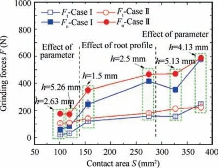
Fig. 5 Effect of wheel-workpiece contact area on changes of grinding force components.
(iii) The grinding force reached the maximum value when the contact area S was increased to 377 mm2.The corresponding h was 4.13 mm.It can be found in Table 2 that apwas increased resulting in large undeformed chip thickness while there was almost no change in the root profile. Under such conditions, the increasing of grinding forces was again mainly caused by the large grinding parameters.
It results from above analysis that the alternating process between the profile of root workpiece and the grinding parameters affected the grinding forces significantly. This means, if the profile of root workpiece(i.e.,accumulated grinding depth h) was kept the same, the aggressive parameters (i.e., large grinding depth ap) could cause the increased grinding forces due to the large undeformed chip thickness. If the grinding parameters were kept constant,the short profile of root workpiece(i.e.,small wheel-workpiece contact area S)could lead to the reduced grinding forces due to the decreased active grains numbers.This probably gives the rough feel for the control of the grinding force by adjusting the parameters and the root workpiece profile in the creep feed grinding process.
3.2. Ground surface topography and surface roughness
Fig. 6 shows the typical surface topography in both the peak region and valley region of the root workpiece ground based on grinding case I. Here, the surface examination positions were marked by the small yellow triangles. As shown in Fig. 6, the surface textures generated were clear and the abrasive grain tracks were uniform.In Fig.7 which shows the typical surface topography of the root workpiece in the grinding case II, these features were also visible but on a less smooth surface.And some slightly black colors were found in the root peak regions as demonstrated in Fig. 7(a), which was possibly the oxidation of workpiece material due to the high grinding temperature.
The surface roughness Sa was measured by the optical microscope and the results are shown in Fig. 8. For grinding case I, the average surface roughness Sa measured in the root peak region and valley region was 0.37 and 0.48 μm, respectively. Grinding case II produced a larger surface roughness(0.8 μm in the root peak region and 1.0 μm in the root valley region) than grinding case I due to the increased smearing and side flow of the workpiece material (Fig. 7). It was also found in both grinding cases that the surface roughness in the root valley region was higher by around 25% than that in the root peak region. The difference in surface quality of root workpiece could be due to the working state variation of wheel surface during profile grinding.
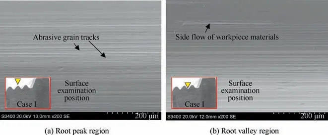
Fig. 6 Typical surface topography in different root regions for grinding case I.
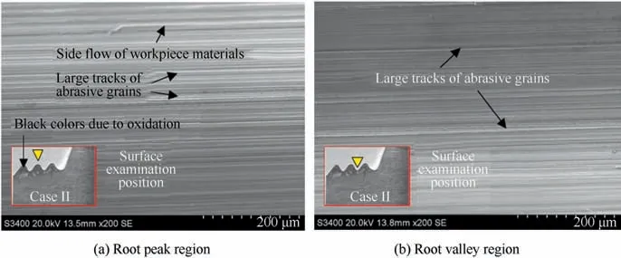
Fig. 7 Typical surface topography in different root regions for grinding case II.
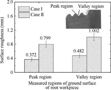
Fig. 8 Ground surface roughness of root workpiece.
In the creep feed profile grinding process, the wheel peak regions are firstly in contact with the workpiece, large impact force and force moment can be caused due to the increasing contact area and active grain numbers in the grinding zone.The wear in the wheel peak regions can be induced in the form of grain wear flat, workpiece material adhesion, and the fractures of grains and bond bridges.28Among these wear patterns the fracture wear plays the predominate role, especially in the creep feed grinding of difficult-to-cut materials,such as nickelbased superalloys.This could result in that the peak regions on the wheel surface are worn more easily and quickly than the valley regions in the profile grinding process,14and therefore tend to cause the dimensional errors and the degraded surface quality of root workpiece. For instance, the fractured grains become the hard particles involving in the grinding process and produce various ground surface defects in the workpiece valley regions.34,35This is the reason why the root peak regions had much smoother surface than the root valley regions. It is also worthwhile mentioning that due to the small parameters used in the grinding pass No.6, few surface defects can be observed in Figs. 6(b) and 7(b). However, the large forces induced by grinding passes No.4 and No.5 could lead to great plastic deformation into the subsurface layer though it might be removed partially by grinding pass No.6. This is the main concern in Section 3.3.In addition,the difference of machining quality on the ground surface was also found in the creep feed profile grinding of the gear forms.36,37The root reason can be attributed to the nonuniform distribution of grinding loads along the profile of workpiece in the normal section during grinding.Continuous dressing of the grinding wheel to recover the profile geometry of the worn tool is thus necessary to guarantee the consistence of surface quality of workpiece.
3.3. Subsurface microstructure
In Figs.9 and 10,along the profile of root workpiece in normal section, the odd numbers of 1, 3 and 5, and the even numbers of 2,4 and 6 were used to represent the root peak regions and valley regions, respectively. Furthermore, Fig. 9 presents the subsurface microstructures of the root peak region No.3, the root valley region No.4 and the middle region between them,which were produced by grinding case I. Because there was no grain boundary inside the single crystal nickel-based superalloy workpiece, the microstructural alternation was difficult to be observed in the ground surface layer from the optical microscope (Fig. 9(a)–(c)). The high resolution micrographs taken by SEM were displayed in Fig. 9(d)–(f) in the same regions,and showed that the strengthening phases of cuboidal γ′-particles were almost absent due to the etching while the matrix phases of γ-channels were apparent.Moreover,bending γ-phases were clearly visible in Fig. 9(d) and (f). The microstructural deformation to a depth of around 3 μm,2 μm and 4 μm in the peak region No.3 (Fig. 9(d)), middle region (Fig. 9(e)) and valley region No.4 (Fig. 9(f)), respectively, was observed in the ground surface layer.
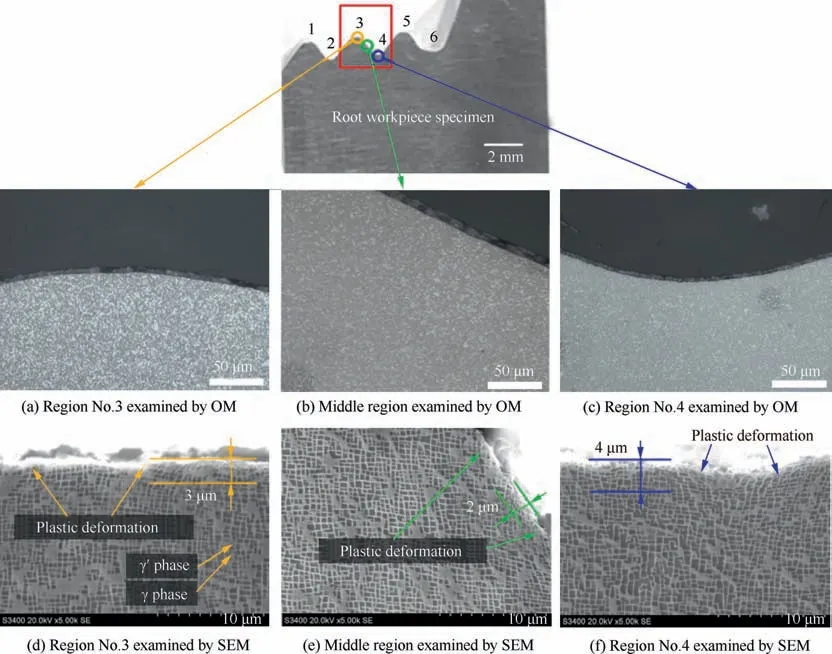
Fig. 9 Microstructure variation on cross section of the root workpiece in grinding case I.
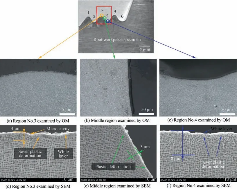
Fig. 10 Microstructure variation on cross section of the root workpiece in grinding case II.
Using the similar characterization method, the subsurface microstructure of cross section of the root workpiece produced by grinding case II was examined,as shown in Fig.10.Similar to the results of Fig. 9(a)–(c), few visible changes of microstructure were found in the surface layer in Fig. 10(a)–(c) through optical microscope. While severe plastic deformation having the depth of about 4 μm, 3 μm and 8 μm was detected by SEM in the peak region No.3 (Fig. 10(d)), middle region (Fig. 10(e)) and valley region No.4 (Fig. 10(f)), respectively. In particular, in the peak region No.3 (Fig. 10(d)), the defects of several micro cavities were generated in the topmost surface,and the continuous white layer to a depth of about 1–2 μm was found.Similar defects were also observed in the root valley region No.4 (Fig. 10(f)).
Fig.11 shows the results of the thickness of the microstructural deformation layer estimated by SEM under different grinding conditions. No doubt that grinding case II had a larger value in the deformation layer thickness than grinding case I. Furthermore, the root valley region was of the deformation layer thickness 4.5 μm for grinding case I and 5.8 μm for grinding case II in average. And the corresponding values in the root peak regions became 3.4 and 4.6 μm. This indicates that the deformation layer thickness of the root valley region was typically higher by up to 23% for grinding case I and 21%for grinding case II, respectively, compared to the root peak region.
During creep feed grinding nickel-based superalloy, the highest plastic deformation is generally formed at the position where the largest grinding forces are generated due to the material removal and wheel wear. This means that, the root valley regions endured greater grinding loads than the root peak regions during profile grinding.In other words, the peak regions on the wheel surface produced larger grinding forces than the valley regions and thus the former can wear more easily.All these led to that the microstructure of the subsurface exhibited great plastic deformation and bending of the γ and γ′phases in the root valley regions,as shown in Figs.9(f)and 10(f). While in the root peak regions, relatively slight plastic deformation was observed. As such, the difference of the subsurface microstructure along the root workpiece profile in the normal section could be created.
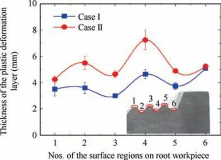
Fig. 11 Variation of the thickness of plastic deformation layer along root workpiece profile in normal section.
3.4. Mechanical properties of ground surface
3.4.1. Microhardness
It is known that the large grinding forces often tend to cause the work hardening of the subsurface as a result of the plastic deformation.38,39While the large amount of heat generated in the grinding zone often raises the thermal softening of the subsurface.40–42The competing process between the work hardening and the thermal softening determines the final state of the subsurface. Usually, for the blade root grinding, the final grinding pass is to removal the grinding burr and obtain the enhanced mechanical properties of the subsurface by using the conservative grinding parameters (i.e., the small grinding depth in grinding pass No.6). Therefore, the work hardening or thermal softening of the subsurface induced by the previous grinding passes might be reduced to some extents. The proper work hardening of the subsurface is always preferred due to the induced compressive residual stress and high wear resistance.
Microhardness variation beneath the ground surface measured for grinding cases I and II are detailed in Figs. 12 and 13,respectively.In the grinding case I,the near surface microhardness of the root workpiece in different regions varied from 444 to 478 HV0.025, which indicated the occurrence of work hardening. The limited surface hardening level of around 3.2–11.1% was produced to a depth of below 10 μm, which corresponded well with the microstructure detection results shown in Fig. 9. In contrast, changes in microhardness (from 469 to 516 HV0.025) subject to grinding case II were more significant as shown in Fig.13.The surface hardening level of different measured regions was generally in the range of 9.1%-20% to a depth of around 30 μm. The microhardness results of the present study indicate the pronounced working hardening of the subsurface, rather than the thermal softening.
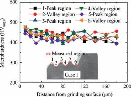
Fig. 12 Microhardness variation on cross section of root workpiece in grinding case I.
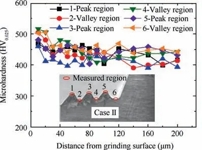
Fig. 13 Microhardness variation on cross section of the root workpiece in grinding case II.
Additionally, the microhardness variation in different root regions was measured. In the grinding case I, the average microhardness in the root peak region was 455 HV0.025, with a work hardening level of 5.8%,while the larger work hardening level(up to 10%)was observed in the root valley region.In the grinding case II, the average microhardness for the root peak and valley region, increased up to 466 and 507 HV0.025,respectively, equivalent to the work hardening level of 8.4%and 17.9%. These results indicate that the work hardening level of the root valley region was approximately twice higher compared to that of the root peak region irrespective of the grinding conditions. The reason for this would be the greater than expected plastic deformation produced by the grinding forces in the root valley regions, as descripted in Section 3.3.
3.4.2. Residual stresses
Compressive residual stress contributes to improving the fatigue life of stress sensitive parts, i.e., the turbine blade root.Due to the small size of root workpiece and testing method of residual stress of single crystal nickel-based superalloy, the stress in the root valley region was difficult to measure by the stress analyzer.Therefore,Fig.14 only displays the results of the residual stresses measured in the root peak regions under two different grinding conditions. As can be seen from Fig. 14, two principle stresses, i.e., σ11and σ22, for grinding case I, were obtained as -86 and -138 MPa, respectively,while they reached -185 and -440 MPa for grinding case II.The compressive residual stresses were generated in both grinding cases I and II.
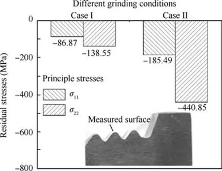
Fig. 14 Residual stresses of ground surface of root workpiece.
The generation of residual stresses in the ground surface is mainly ascribed to the thermal expansion and phase transformation due to the grinding temperature,and the plastic deformation due to the grinding forces.43The above analysis on the microstructure alternation and work hardening of the subsurface suggests that the grinding forces had the more pronounced effect than the grinding temperature for both grinding cases. Thus, the residual stresses were mainly produced by the mechanical interactions between the grinding wheel and the workpiece. The variation of the mechanical properties of the subsurface can be due to the plastic deformation resulted from the grinding forces. In addition, as can be seen from Fig.14,the aggressive parameters(i.e.,grinding case II) can removal large volume of materials while leading to the high grinding forces and the workpiece appearance changing as well. By comprehensively taking into consideration of the surface topography, subsurface plastic deformation and work hardening, the parameters in the grinding case I might be the superior choice for achieving the better quality of machined surface in the creep feed profile grinding of blade root workpiece,though grinding case II produced the higher compressive stresses on the ground surface.
4. Conclusions
In the present study, the profiled microcrystalline alumina abrasive wheels were employed to creep feed grind single crystal nickel-based superalloy for achieving the fir-tree blade root forms.Grinding force and surface quality were evaluated comparatively by using two different groups of parameters. The main results are concluded as follows:
(1) During creep feed profile grinding of the blade root forms, the combined effects from the grinding parameters and the cross-sectional profile of root workpiece on the grinding forces were found.That is,the root profile had more effects on the grinding forces compared to the grinding parameters when the target root profile wasn’t completely finished, while the grinding parameters dominated the grinding forces when the target root profile was achieved.
(2) Regardless of the grinding parameters, the surface roughness, the subsurface plastic deformation layer,and the work hardening level in the root valley regions were found to be higher by 25%,22%and 7%on average than those obtained in the root peak region, respectively, in the current investigation.
(3) In the present study, both grinding cases I and II could produce the ground surfaces with favorable compressive residual stresses (σ11=-86 MPa and σ22=-138 MPa for grinding case I, σ11=-185 MPa and σ22=-440 MPa for grinding case II.).However,grinding case I might produce the better surface quality (i.e., on average,the defect-free surface with Sa 0.43 μm, the subsurface plastic deformation of 4 μm, and the work hardening level of 7.9% to a depth of below 10 μm) in the creep feed profile grinding of the blade root forms in general.
Acknowledgements
The authors gratefully acknowledge the financial support for this work by the National Natural Science Foundation of China (No. 51775275), the Funding of Jiangsu Innovation Program for Graduate Education of China (KYCX17_0245),the Funding for Outstanding Doctoral Dissertation in NUAA of China (BCXJ17-04), the Fundamental Research Funds for the Central University of China (No. NP2018110), the National Science and Technology Major Project and the Six Talents Summit Project in Jiangsu Province of China (No.JXQC-002).
 CHINESE JOURNAL OF AERONAUTICS2021年2期
- CHINESE JOURNAL OF AERONAUTICS的其它文章
- Recent active thermal management technologies for the development of energy-optimized aerospace vehicles in China
- Electrochemical machining of complex components of aero-engines: Developments, trends, and technological advances
- Recent progress of residual stress measurement methods: A review
- Micromanufacturing technologies of compact heat exchangers for hypersonic precooled airbreathing propulsion: A review
- Towards intelligent design optimization: Progress and challenge of design optimization theories and technologies for plastic forming
- A combined technique of Kalman filter, artificial neural network and fuzzy logic for gas turbines and signal fault isolation
