A tip clearance prediction model for multistage rotors and stators in aero-engines
Huiin SUN, Jing WANG, Ki CHEN, Huteng XIA, Xin FENG,Zhiyong CHANG,*
a Key Laboratory of High Performance Manufacturing for Aero Engine, Ministry of Industry and Information Technology, Northwestern Polytechnical University, Xi’an 710072, China
b AECC South Industry Company Limited, Zhuzhou 412002, China
KEYWORDS Tip clearance;Prediction;Error propagation model;Rotor and stator;Aero-engine;Assembly
Abstract Tip clearances of multistage rotors and stators greatly affect aero-engines’ aerodynamic efficiency,stability and safety.The inevitable machining and assembly errors,as well as the complicated error propagation mechanism,cause overproof or non-uniform tip clearances.However,it is generally accepted that tip clearances are difficult to predict, even under assembly state. In this paper, a tip clearance prediction model is proposed based on measured error data. Some 3D error propagation sub-models,regarding rotors,supports and casings,are built and combined.The complex error coupling relationship is uncovered using mathematical methods. Rotor and stator tip clearances are predicted and analyzed in different phase angles.The maximum,minimum and average tip clearances can be calculated. The proposed model is implemented by a computer program,and a case study illustrates its performance and verifies its feasibility.The results can be referred by engineers in assembly quality judgement and decision-making.
1. Introduction
Tip clearances of Multistage Rotors and Stators (MRS) are extremely important factors affecting performance and safety of aero-engines.1In the aero-engine design stage, engineers design ideal tip clearances. However, part machining errors and their complex couplings in the assembly process are inevitable, resulting in overproof or non-uniform tip clearances.Under the working condition, unreasonable clearances lead to the perturbations of circumferential pressure and axial flow velocity. Thus surge, impact and rubbing may be caused to reduce the working efficiency and stability of the aero-engine.2–5Therefore,it is absolutely significant to investigate tip clearances.
However, tip clearances are difficult to predict, even under assembly state.6Tip clearances are affected by many factors,including rotor runout,rotor coaxiality,stator runout,support deformation, bearing clearance, and so on. These rigid and flexible factors are closely coupled. Most tip clearances are in the range 0.5–1.5 mm. Such a high requirement makes the accurate prediction even difficult. Under this case, tip clearance prediction becomes a vital problem in the assembly of MRS.
Aiming at this problem,this paper proposes a tip clearance prediction model for MRS based on measured error data.The Error Propagation Models(EPMs),regarding rotors,supports and casings, are studied. Rotor and stator tip clearances are predicted and analyzed in different phases. The maximum,minimum and average tip clearances are calculated.The results can be referred by engineers in assembly quality judgement and decision-making.
The rest of this paper is organized as follows. A review of recent research on tip clearances and error propagation is given in Section 2.A brief description of the tip clearance prediction model is discussed in Section 3.Section 4 addresses the modeling process of three-dimensional (3D) error propagation.In Section 5,a case study is used to verify the model’s feasibility. Finally, a brief summary and conclusions are given in Section 6.
2. Literature review
Regarding tip clearances of MRS, existing studies focused on two aspects:tip clearance inspection and assembly error propagation modeling.Normally,tip clearance inspection methods used eddy current,7optical fiber probe,8,9microwave,10capacitance,11and laser.12However,tip clearances and the changing law couldn’t be measured easily. These methods were limited by both the inspection technologies and the openness of the objectives. Most of them could only be used for the rotor tip clearance measurement at very limited phases. Because of the space limitation and occlusion, the stator tip clearances were unmeasurable.Therefore, the detailed non-uniform circumferential distributions of tip clearances after assembly were still unknown.
Recently, great efforts have been made in modeling and analyzing the effect of tip clearance on the performance and safety of aero-engines. For example, the effect of nonuniform radial and axial tip clearances on the flow velocity and blade pressure has been studied.13And a numerical analysis for tip clearance geometries has been done, which provided a design method of tip clearance geometries for optimizing performance.14Furthermore, the influence of tip clearances on tip leakage has been simulated respectively.15,16In addition, a study showed that designing axially nonuniform clearances was an effective strategy to reduce tip leakage.17A distributed collaborative extremum response surface method has been used to estimate the performance of aeroengines under working conditions.18In general, these studies provided performance-oriented optimization and improvement methods regarding tip clearances. However, they were normally based on ideal and uniform tip clearances.The influence of part machining errors and assembly errors on tip clearances has been seldom considered.
In fact, a lot of data was involved in the assembly process,including parts’ dimension errors, form errors and position errors. These data could be used to predict assembly accuracy and key performance indexes,based on the EPM of the assembly process. For example, EPMs have been utilized to minimize initial unbalance and eccentricity in assembly of multistage rotors.19,20A novel error analysis methodology related to measurement-assembly equipment was proposed,which improved the assembly and measurement accuracy of aero-engine multistage rotor.21And a dimensional chain calculation model has been built for a turbine assembly, which addressed the influence of a geometrical parameter tolerance on the dimensional chain-link elements.22Assembly error feature-based analysis methods were proposed to evaluate the safety and aerodynamic performance of the turbine,which were experimentally verified.23A virtual assembly method has been used to estimate the assembly quality of an aero-engine that was conducive to analysis for error propagation mechanism.24To ensure the overall concentric performance of vibration-free and noise-free aero-engine assembly, the assembly technique of multistage rotational optimization and the deviation propagation model have been investigated for revolving components assembly.25And an EPM method has been presented to guide the stacking assembly for cylindrical components like multistage rotors.26In addition, a prediction and control method has been put forward for turbine tip clearances of aero-engines. The tip control system had a favorable steady-state with increased efficiency,reduced specific fuel consumption, and additional service life.27
In summary,problems in existing researches mainly include two aspects as follows:
(1) Numerous researches have investigated rotor and stator tip clearances,and their influence on aero-engine performance, safety and stability. Based on ideal part models,the results is very limited for assembly quality judgement.
(2) Actual tip clearances result from complex coupling of part machining errors and assembly errors. Without a compressive EPM, it is impossible to predict rotor and stator tip clearances accurately.
3. Tip clearances prediction model
Based on the above analysis, this paper proposes a tip clearance prediction model for MRS in aero-engines. Rotor and stator tip clearances are affected by numerous part machining errors and complex assembly error propagation. Without loss of generality,rotors composed of blisks are investigated.Rotor and stator tip clearances are predicted for assembled aeroengines when their central lines are parallel to the horizontal plane. The model can be suitable for various compressors,no matter they have constant inner-diameter, outer-diameter or medium-diameter flow-paths.
Prior to tip clearance prediction, machining and assembly errors related to tip clearances are illustrated in Fig.1 and discussed as follows.
Fig. 1(a) Elliptical deformation. Due to the weak rigidity and residual stress releasing, elliptical deformation changes the contour of the internal surfaces.
Fig.1(b)Eccentricity.Due to the machining errors,a part’s actual centroid is different from its ideal position. The eccentricity changes the relative position of the casing and rotor in the radial direction.
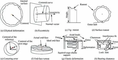
Fig. 1 Schematic diagram of errors.
Fig. 1(c) Tip runout. As to a rotor or a casing, blade tip runout or vane tip runout is inevitable and un-ignorable,although it is usually no more than 0.03 mm.
Fig. 1(d) Surface runout. Similar to tip runout, the surface runout is normally within 0.05 mm.
Fig.1(e)Centering error.The centering error occurs on the fit surfaces of two adjacent parts, which changes the ideal multi-part centroid curve.
Fig. 1(f) End-face runout. End-face runout results in an actual end face,which leads to deflection of the centroid curve of the next stage.
Fig. 1(g) Elastic deformation. Under axial or radial loads,thin-wall parts are likely to deform.
Fig. 1(h) Bearing clearances. Bearing clearances, including radial clearances and axial clearances, greatly affect the coaxiality of MRS.
Almost all factors are geometric values. Raw position, size and distance data can be acquired using a Coordinate Measuring Machine(CMM).Raw radial and axial runout data can be acquired using one or more electronic micrometers (e.g.Mituyoto Mu-checker 519-326MLH-326). Eccentricity can be fitted using acquired raw data. To enable the following fitting and modeling, raw data should be enough considering accuracy requirements. How to obtain necessary data as soon as possible becomes a big problem. In the future, advanced measuring equipment, e. g. Renishaw REVO, can be used to acquire huge data efficiently. Moreover, bearing clearances and deformation of elastic supports are difficult to measure.They can be determined according to empirical formulas or documents.
In the assembly process,errors discussed above are closelycoupled. Before investigating their contributions to rotor and stator tip clearances, they are cataloged into the following three types according to the aero-engine structure (as shown in Fig. 2).
(1) Rotor system errors.Rotor tip clearances are affected by blade heights and rotor tip runouts. These values vary greatly with different phases, even within the same cross-section. The actual centers of multiple rotor parts are not in a line. Due to end-face runouts and radial eccentricity of parts,and centering errors between parts,the actual central line can’t be found.
(2) Stator system related errors. The shapes of casing internal surfaces contribute to rotor tip clearances.The radii and runouts of internal surface cross-sections change the ideal rotor tip clearances.Due to the weak rigidity,elliptical deformation of casings changes the contour of the internal surface and leads to non-uniform rotor tip clearances. End face runouts may deflect the centroid curve of multiple adjacent annular casings. Stator tip runouts and vane height errors are of great importance for stator tip clearances.
(3) Support system related errors. Support system includes bearings and elastic supports. Radial and axial clearances of bearings reduce the coaxiality of MRS. Due to gravity and assembly stress, deformation of elastic supports changes the relative position and orientation between rotors and stators.
The proposed prediction model considers all errors discussed above and formulates them mathematically in a 3D Cartesian coordinate system.As shown in Fig.3,the proposed model is composed of the following sub-models.
(1) The rotor sub-model is based on the staking assembly of multi-stage rotors. Regarding a part, radial eccentricity and end-face runout are merged to calculate the center.The coaxiality is calculated based on the staking of multiple parts. Based on the propagation of geometric errors, this sub-model outputs the precise location of rotor blades and outer hubs.
(2) The stator sub-model considers the assembly of multiple casings. Fitted internal surface, radial eccentricity, and end-face runout are merged to calculate the coaxiality.This sub-model outputs the non-uniform stator tip height and deformed internal surface for tip clearance prediction.
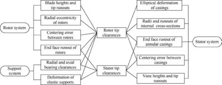
Fig. 2 Relationship between key errors and tip clearances.
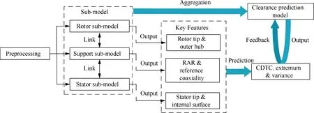
Fig. 3 Rotor and stator tip clearance prediction model.
(3) The support & bearing sub-model considers errors of elastic supports and bearings. The coaxiality of bearing inner rings and outer rings is predicted using the bearing clearances and the deformation of the elastic supports.Then,the positions of bearings can be calculated to connect the rotor system and the stator system.
(4) The integration model combines all sub-models and calculate rotor and stator tip clearances. Regarding a phase, the clearances of all tips can be predicted respectively. Regarding a rotor or stator tip, the clearances in all phases can also be predicted.
As discussed above,EPM is vital to all sub-models.The following section will address this issue in detail.
4. Error propagation modeling
As shown in Fig. 4, the error propagation paths of an MRS include the following three steps.
(1) The preprocessing step is based on design models and measured raw data. Actual error features (e.g., circles,planes, ellipses, etc.) of the parts are fitted using the Least Square Method (LSM).
(2) The error propagation step builds EPMs for rotors,stators,bearing and support,respectively.Above error features are combined. A global EPM is built by transforming local coordinate systems into the Absolute Coordinate System (ACS).
(3) The prediction step outputs rotor and stator tip clearances.Regarding every phase,the maximum,minimum,and average tip clearances are calculated, respectively.The distribution of tip clearances in different phases can also be calculated by rotating the rotor.
4.1. Preprocessing
Acquired raw data is included in a point set in the Measurement Coordinate System(MCS).Then,a Homogeneous Coordinate Transformation (HCT) is done by matrix T as28

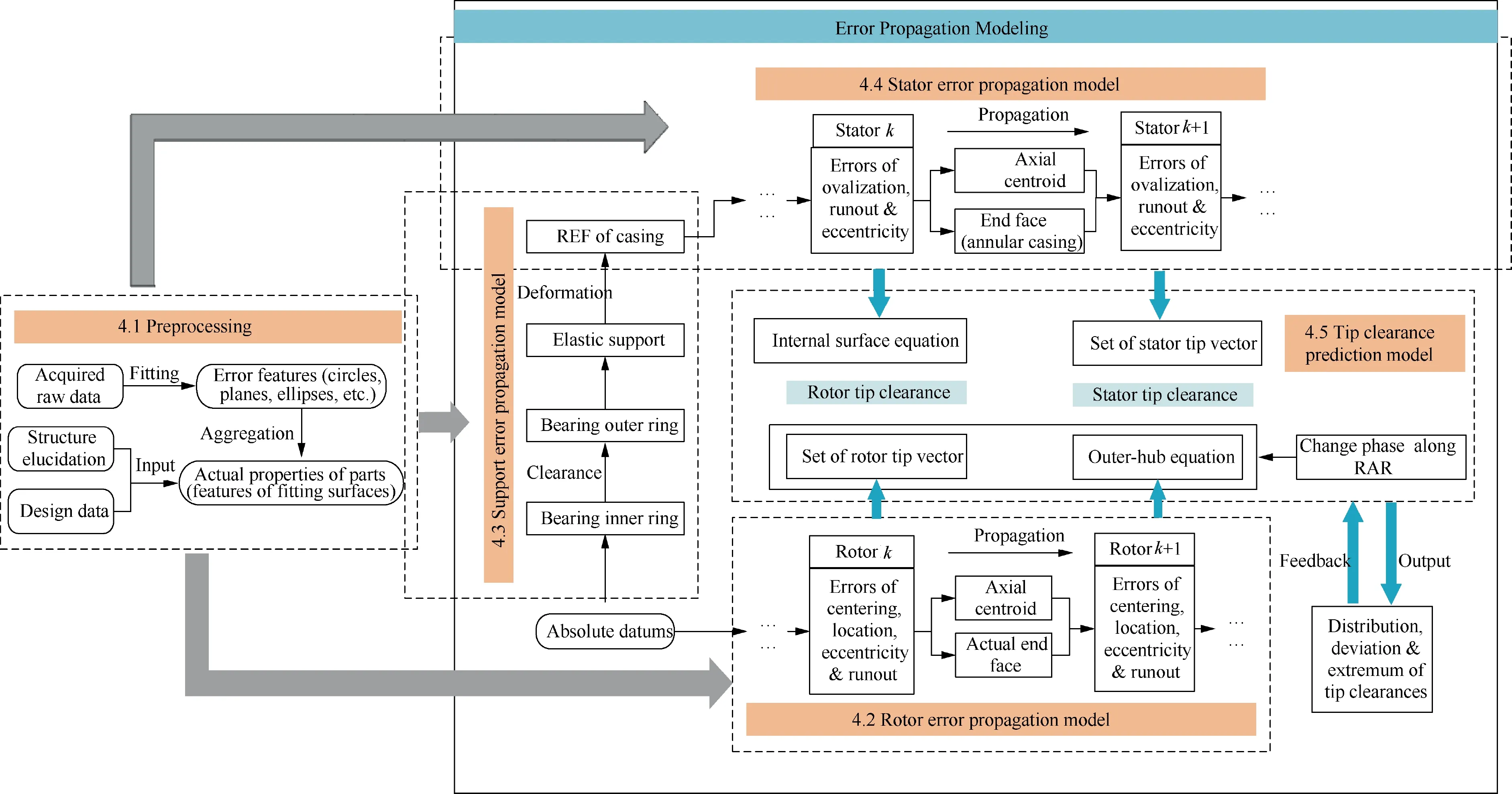
Fig. 4 Procedure of EPM.

(1) End Face Runout. According to above discussions, the machining accuracy of the end face is extremely significant for concentricity. The following plane is used to describe the actual end face, which is validated by the Small Displacement Torsor (SDT) method.29
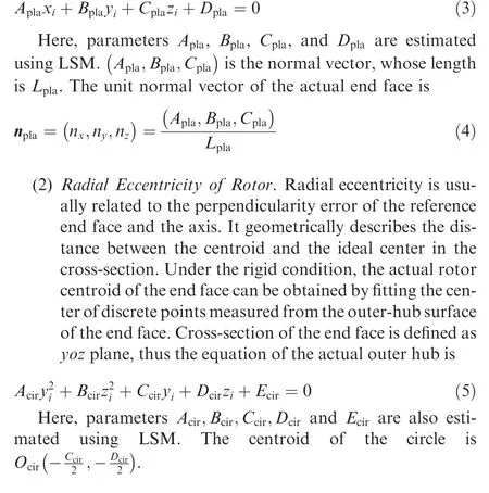
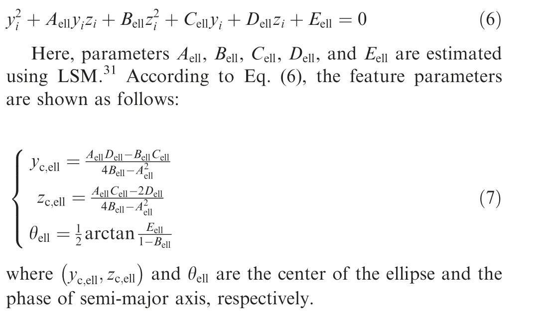
(3) Radial Eccentricity of Internal Surface.As a typical part with weak rigidity,the casing’s errors are rigid-flexibility coupled. The cross-section of a casing’s ideal internal surface is a circle. However, due to the deformation, it is closer to an ellipse.30Therefore, the ellipse equation is used to describe the cross-section. The reference end face is the yoz plane, and its centroid is the origin of the coordinate system. Then a cross-section of an internal surface is
4.2. Rotor error propagation model
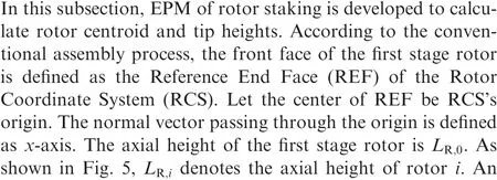
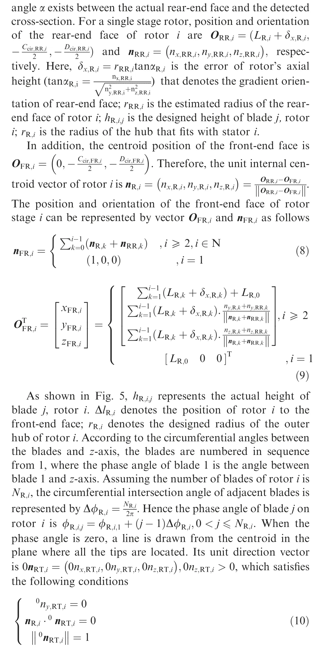
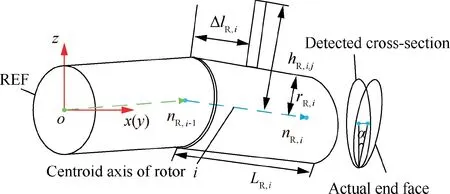
Fig. 5 Schematic diagram of rotor error modeling.
where nR,i·0nRT,i=0 denotes the vertical relationship between the direction vector of zero phase angle and the centroid axis.Hence the unit direction vector of tip on blade j of rotor i,denoted as nRT,i,j, can be gotten by rotating 0nRT,iaround the internal centroid axis nR,ias
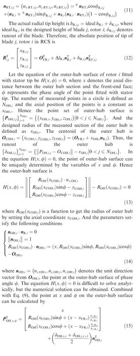
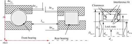
Fig. 6 Schematic diagram of bearing clearance.

4.3. Support error propagation model
The assembly errors of the support system mainly come from bearing clearances and elastic support deformation, which affect the connection between the rotor system and the stator system.
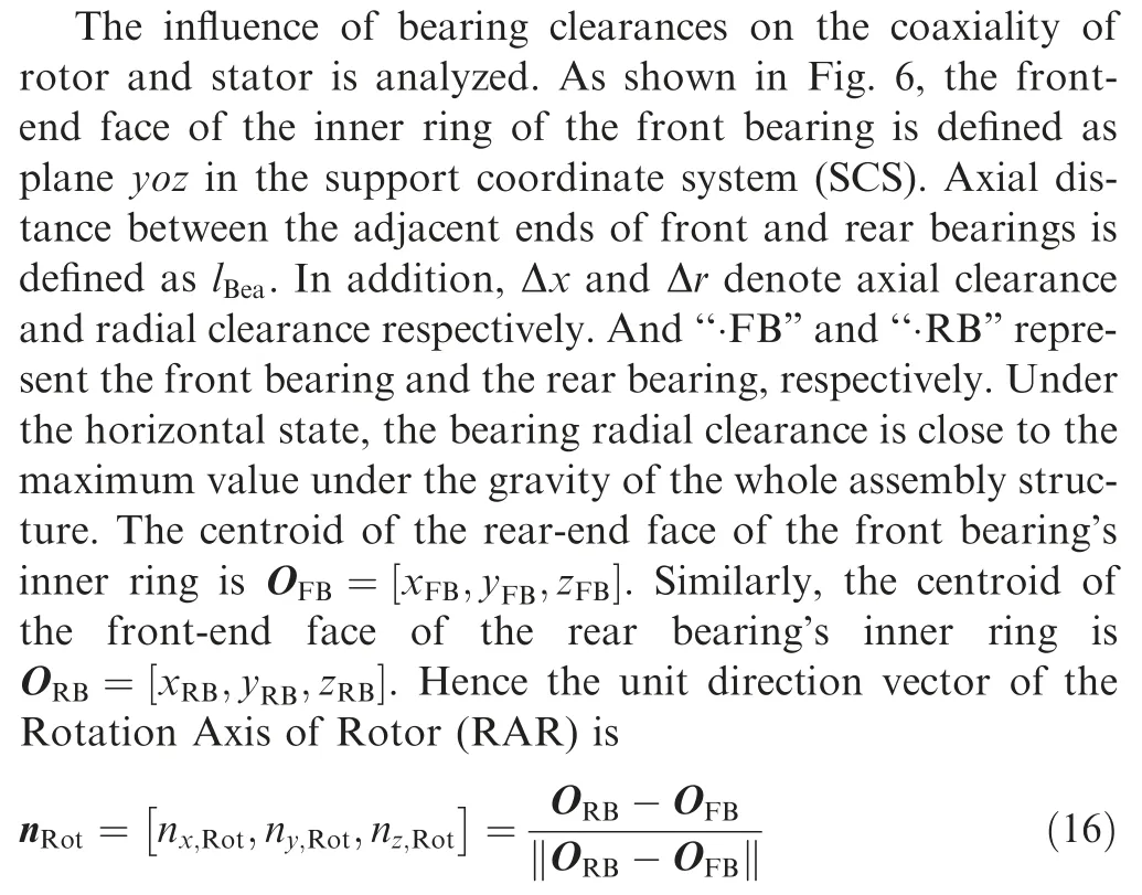
The deformation of a single bearing and an elastic support are also analyzed, respectively.
(1) Bearing deformation.In the assembly state,there are two types of load on the rolling bearing:locking stress of the nuts and contact stress of interference fit. The deformation caused by them changes the radial clearances of the bearings.
(a) Contact stress of interference fit. As shown in Fig. 6, for a single bearing, the interference fit is applied to both inner and outer rings. Therefore,the inner ring is squeezed by the contact stress and expands, and the increment Δδbea,inis32

where dbeais the inner diameter of the bearing;dbea,gis the raceway diameter of the inner ring;ds,0is the inner diameter of the hollow shaft. If the shaft is solid, ds,0=0 is true. Ebeaand νbeaare the elastic modulus and Poisson’s ratio of the bearing material, respectively. Esand νsare elastic modulus and Poisson’s ratio of the shaft.Δfbea,inis the magnitude of interference between inner ring and shaft. Contrary to the inner ring, the outer ring is compressed by the contact stress,and the diminution Δδbea,outof the outer ring is32
Δδbea,out

where Dbeais the outer diameter of the bearing; Dbea,gis the raceway diameter of the outer ring;Dbea,his the outer diameter of the elastic support; Ebea,hand νbea,hare elastic modulus and Poisson’s ratio of the elastic support;Δfbea,outis the magnitude of interference between outer ring and elastic support.
(b) Locking stress of the nuts.To avoid relative motion,lock nuts are mounted on the end face of the inner and outer rings.And the positive pressure applied by the nuts causes deformation of the rings. However, the deflection was proved to be very small to be considered in this work.32
(c) Gravity of the core-engine. Under the horizontal state,the rotor is naturally sagged by gravity, which produces local pressure on the bearing. Taking a Cylindrical Roller Bearing(CRB)and a single row Angular Contact Ball Bearing (ACBB) for examples, the local radial displacement Δδbea,gcan be estimated by

where Gris the gravity component of the core-engine carried by the bearing; nbeais the number of the rollers; Lrolis the length of single roller; βbeais the contact angle of the bearing;dballis the diameter of the ball roller.
Considering the above bearing deformation analysis, the sinking displacement Δδbeaof the outer ring in the horizontal assembly state is
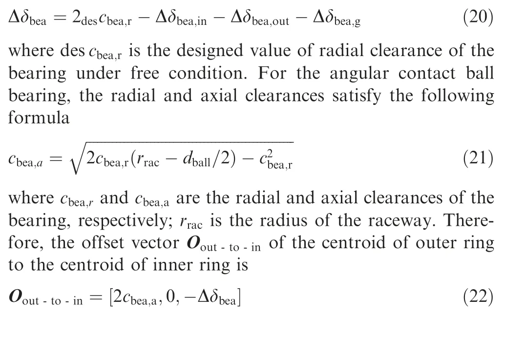
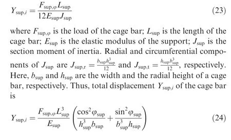
(2) Elastic support. Elastic support is an important bearing and damping component of aero-engines in the working condition. The squirrel-cage elastic support is the most common structure. Therefore, its stiffness and deformation under the assembly state are analyzed in detail. As shown in the left sub-graph of Fig. 7, the gravity of the core-engine leads to deformation of the elastic support under the horizontal state. When the elastic support is subjected to the radial load, displacement of every cage bar is different.
A cage bar’s displacement is
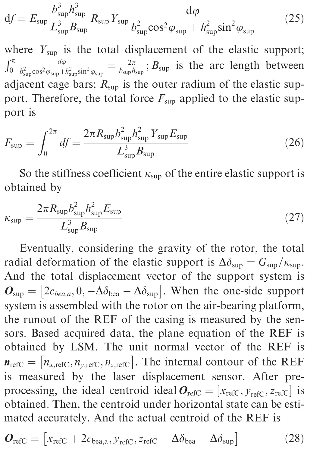
The differential of force on the cage bar is
4.4. Stator error propagation model
Due to the weak rigidity, casings deform inevitably.30In this section, the rigid-flexibility coupled EPM of casings is analyzed. Axial-flow casings mainly include two types, namely,the split casing and the annular casing. They have different error formation and propagation rules as follows.


Fig. 7 Force analysis of squirrel-cage elastic support.
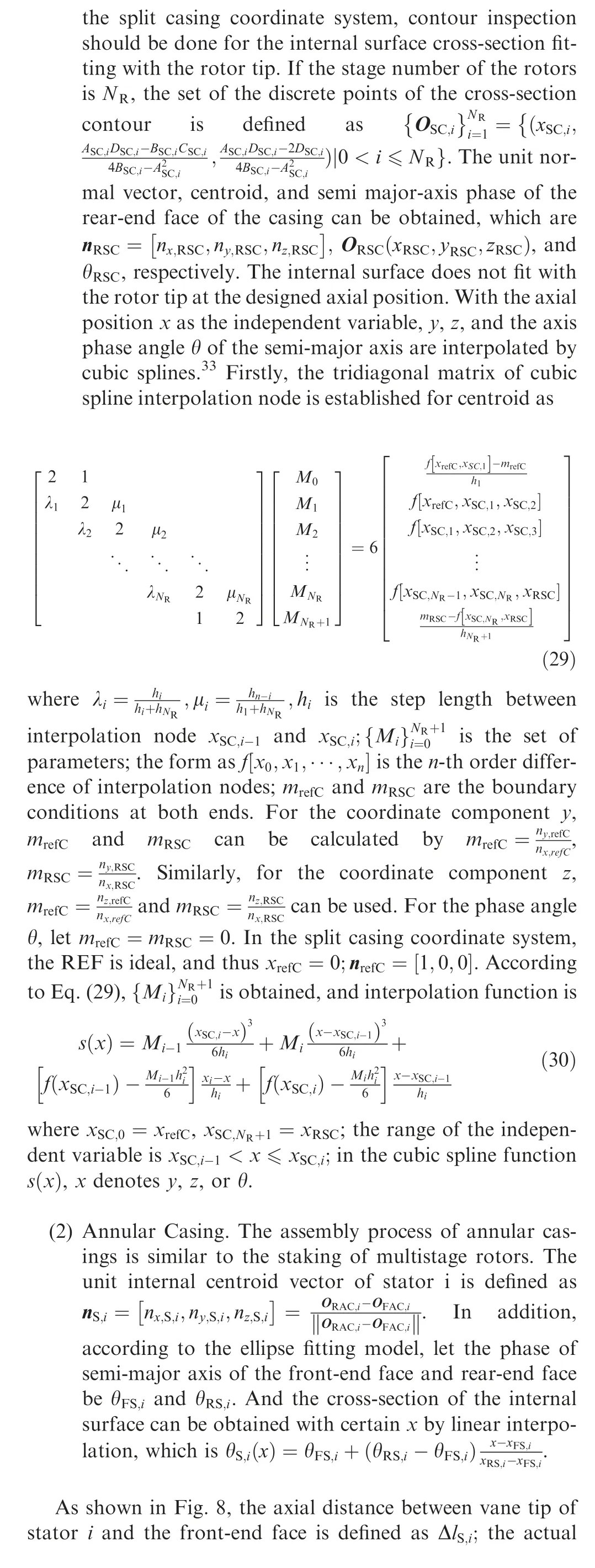
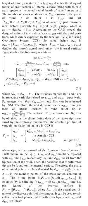
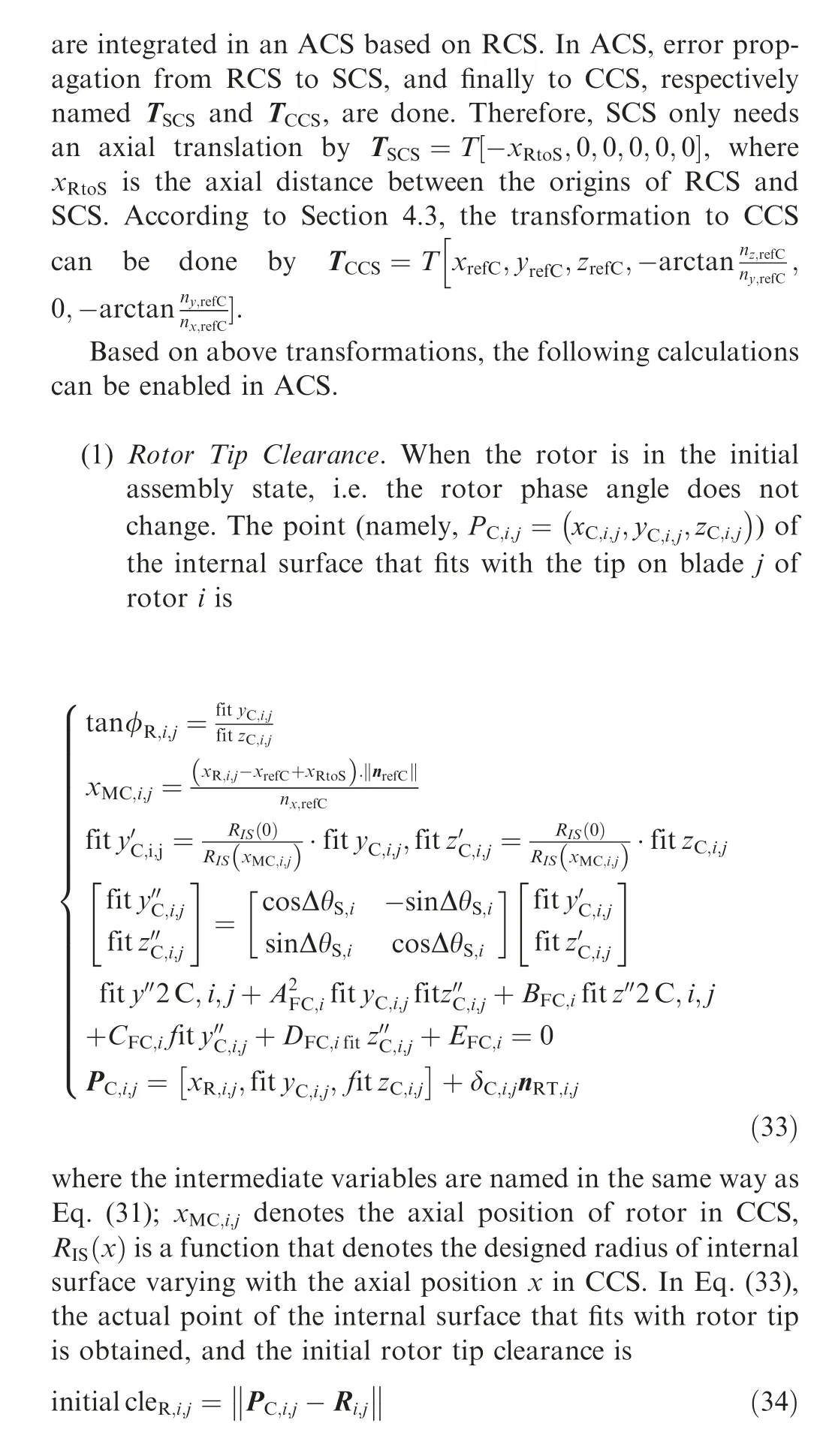
4.5. Tip clearance prediction model

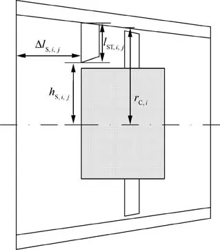
Fig. 8 Schematic diagram of casing.
As is shown in Fig. 9, the RAR marked in dashed line is determined by the installation positions of the inner rings of bearings. And the centroid axis of rotor marked in thinner solid line is composed of some discontinuous segments. The non-axiality of the RAR and centroid axis of the rotor leads to the height of the rotor tip changing with phase, eventually resulting in tip clearance fluctuation. In addition, owing to the misalignment of the rotor’s centroid axis and RAR, rotor tip height changes with the rotor phase. Hence a variable of phase θRotis set to predict rotor tip clearance with different phases. Then, θRotthe rotor tip position and height change according to the following equation.
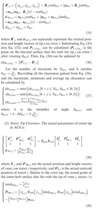
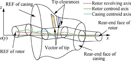
Fig. 9 Effect of non-coaxiality between stator and rotor on tip clearance.
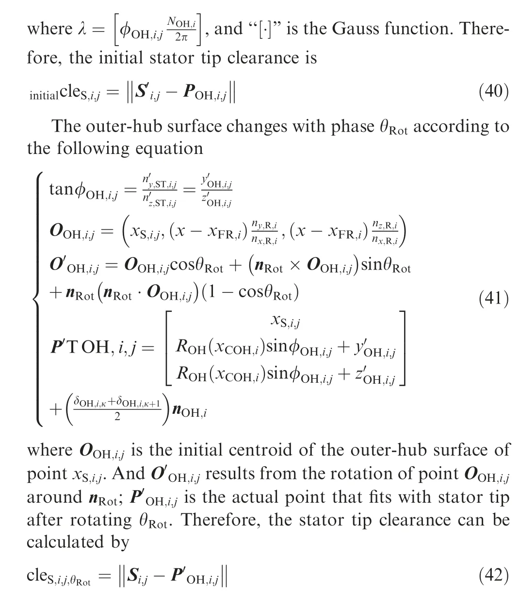
According to Eq. (37), the maximum, minimum and average values of stator tip clearance can be obtained similarly.
5. Experimental study
5.1. Experiment setup
An axial flow compressor is used to illustrate and verify the proposed model.Key design parameters are shown in Table 1.
All raw data is saved in a file, which is too large to be displayed in the paper.Based on C++and MATLAB platform,the proposed model is implemented as a computer program.As shown in Fig.10,the program includes three modules:preprocessing, computing, and results.
(1) Preprocessing.The number of stages and the type of casing are selected before preprocessing. CAD model data and measured raw data of rotors, stators and supports are inputted. Examples of measured raw data and CAD model data of a rotor are shown in Figs. 11 and 12, respectively.
(2) Computing. When all data is ready, the program calculates step by step according to the modeling modules.
(3) Results. The result interface is displayed in Fig. 13. In response to user selections, various charts can be shown to visualize the prediction results.
5.2. Prediction results & analysis
Prior to obtaining tip height and surface equation related to tip clearances, the inner centroid of the casing is interpolated by cubic splines. The non-axiality of RAR is also calculated. As shown in Fig. 14, the predicted initial centroids of rotor and casing along x-axis provide a basis for the tip clearance prediction.
The initial positions of the rotor tip can be obtained by Eq.(12).Let the tip rotate slowly around RAR,and the new positions can be obtained by Eq. (35). According to the modeling process, the coaxiality of MRS shows significant effect on tip clearances.Hence,the predicted centroid curves are important evidence for strictly controlling tip clearance.
When the tip positions with different phases are calculated,the tip clearance distribution of each stage can be obtained.For example, tip clearance of rotor 1 and stator 1 are shown in Fig.15.The symbols‘‘+”and‘‘-”denote predicted outlierand the median, respectively. The top and bottom of the unit box represent the upper and lower quartiles, respectively.

Table 1 Key parameters of the axial flow compressor.
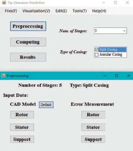
Fig. 10 User interface design of the tip prediction program.
In Figs.15(a)and(b),the statistical unit denotes the clearance distribution of all circumferential tip clearances under a certain rotor phase. If data of different phases is sufficient enough,the box units change continuously along the abscissa.The median of rotor tip clearance and stator tip clearance change with the rotor phase. The reason is that the radial distance between rotor centroid and casing centroid changes periodically when the rotor centroid (shown in Fig. 14) rotates around RAR.
In Figs. 15 (c) and (d), the unit box represents the fluctuation of tip clearance of a single blade with different phases.The statistical unit reflects the coupling effects of rotor tip runout and non-uniform distribution of rotor tip height along the circumference. The fluctuation shows the coupling effects of stator tip runout and the elliptical deformation of the casing.Overall,the tip runout and the elliptical deformation of casing are the most significant factors affecting tip clearances.
The experiment results are summarized in Fig.16.Predicted tip clearances of every stage wave in the range from-0.15 mm to +0.15 mm. Meanwhile, a small number of predicted outliers are marked. The reason can be traced back to the boxplots in Fig.15.For example,the whole tip clearances of vane 11 on stator 1 deviate from the designed values, and its tip should be ground for about 0.05 mm again.
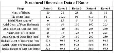
Fig. 12 An example of designed data of a rotor from CAD models.
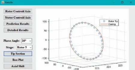
Fig. 13 Brief display interface of results.
The predicted maximum, minimum, and mean tip clearances are displayed in Table 2. These values can be referred by engineers in assembly quality judgment.
5.3. Discussions
As discussed above,both rotor and stator tip clearances can be predicted. The maximum, medium and minimum clearances have been calculated and visualized. The model can be used to predict tip clearances of compressors, no matter they have constant inner-diameter, outer-diameter or medium-diameter flow-paths. The results could be valuable for engineers. The proposed model is essential for a digital twin model, which could make a close-loop mapping relationship between the prediction model and the physical assembly. However, some limitations still exist. For example, more experiments should be done to verify the accuracy, although they are costly and time-consuming physical.
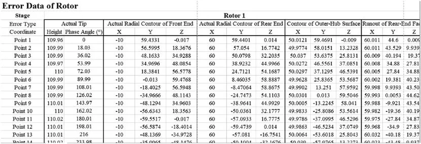
Fig. 11 An example of measured raw data of a rotor.
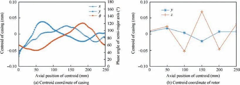
Fig. 14 Variation of centroid along the x-axis.
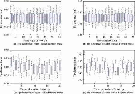
Fig. 15 Box-plot of the tip clearance of rotor 1 and stator 1.
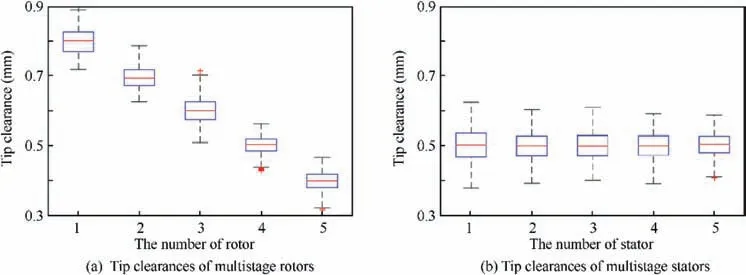
Fig. 16 Box-plot of tip clearance fluctuation of MRS.

Table 2 The results of tip clearance of MRS (unit: mm).
6. Conclusions
In this work,a prediction model for rotor and stator tip clearances based on measured raw data is proposed and shows the following conclusions:
(1) By building and combining EPMs of rotors, stators,supports, and bearings, the proposed model can predict rotor and stator tip clearances. Detail values, including clearance distribution,the maximum,medium,and minimum clearances can also be calculated.The results provide a valuable reference for quality judgment and assembly parameter optimization.
(2) An experiment verifies the feasibility of the proposed model. It also uncovers that the non-axiality between rotor centroid and stator centroid is an important factor for the nonuniformity of the initial tip clearances. The phase of the rotor has a significant effect on the fluctuation of tip clearances due to the non-axiality of the rotor centroid axis and RAR.
However, some existing limitations call for further researches. For example, based on the proposed model, a digital twin model could be developed to make a close-loop mapping relationship between the prediction model and the real assembly process. More inputs, such as the thermal load, can be included in the proposed model to predict tip clearances under working conditions.
Declaration of Competing Interest
The authors declare that they have no known competing financial interests or personal relationships that could have appeared to influence the work reported in this paper.
Acknowledgements
This study was co-supported by the Equipment Pre-Research Foundation (No. 61409230204), the National Basic Research Project (No. 2017-VII-0010-0104), the Defense Industrial Technology Development Program (No. XXXX2018213 A001), the National Natural Science Foundation of China(No.51875475)and the Key Development Program of Shaanxi Province(Nos.2018ZDXM-GY-068 and 2016KTZDGY4-02).
 CHINESE JOURNAL OF AERONAUTICS2021年2期
- CHINESE JOURNAL OF AERONAUTICS的其它文章
- Recent active thermal management technologies for the development of energy-optimized aerospace vehicles in China
- Electrochemical machining of complex components of aero-engines: Developments, trends, and technological advances
- Recent progress of residual stress measurement methods: A review
- Micromanufacturing technologies of compact heat exchangers for hypersonic precooled airbreathing propulsion: A review
- Towards intelligent design optimization: Progress and challenge of design optimization theories and technologies for plastic forming
- A combined technique of Kalman filter, artificial neural network and fuzzy logic for gas turbines and signal fault isolation
