Effects of pressure oscillation on aerodynamic characteristics in an aero-engine combustor
Hao QIN, Guanqiong TANG, Xionghui WANG
Design and Research Center, AECC Commercial Aircraft Engine Co., Ltd., Shanghai 200241, China
KEYWORDS Aerodynamic;Aero-engine;Combustor;Multiple Linear Regression;Nonlinear;Phase trajectory reconstruction;Pressure oscillation
Abstract The effects of pressure oscillation on aerodynamic characteristics in an aero-engine combustor are investigated. A combustor test rig is designed to simulate the pressure drop characteristics of a practical annular combustor. The pressure drop characteristics are firstly measured under atmosphere condition with non-reacting flow (or cold flow), and the air mass flow proportion of each component(dome/liner)are obtained;these properties are base lines for comparison with combustion state.The combustion tests are then carried out under conditions of inlet temperature 340–450 K, fuel air ratio 0.010–0.028. The stability map and the oscillation frequencies are obtained in the tests, the results show that pressure oscillation amplitude increases with the increase of fuel air ratio.Phase trajectory reconstruction is applied to classify the pressure oscillation motion;there are three motions captured in the tests including: ‘‘disk”, ‘‘ring” and ‘‘cluster”. The pressure drops across the dome under strong pressure oscillation are distinctly divergent from the cold flow, and the changes of pressure drops are mainly affected by pressure oscillation amplitude,but is less influenced by pressure oscillation motion nor oscillation frequencies. Based on the mass flow conservation, the reduction of effective flow area of combustor under strong pressure oscillation is demonstrated. Liner wall temperatures are analyzed through Multiple Linear Regression (MLR)method to estimate the reduction of the air mass flow proportion of the liner cooling under strong pressure oscillation. Finally, the air mass flow proportions of each component under strong pressure oscillation are estimated, the results show that the pressure oscillation motion also has influence on air mass flow proportion.
1. Introduction
To design a gas turbine combustor, the pressure drop and air mass flow proportion of each component of combustor (such as swirler,liner,etc)are firstly designed after defining the combustor type. The pressure drop and air mass flow proportion(or air distribution) have great influences on combustion efficiency, ignition, temperature transverse quality, emissions and instabilities.1For modern civil aircraft engine combustor,lean burn technology has been applied to satisfy emission certificate.2That is,much more air is supplied into the dome swirlers,and less air for liner cooling.In this situation,combustion instabilities easily occur.3Specially, during the engine acceleration at which the fuel air ratio is higher, the pressure oscillation amplitude in combustor shall become larger.4To avoid the fatigue of high temperature components induced by combustion instabilities, active control5,6and passive control strategies (such as staged burning technology7,8) are applied.
Large amount of experiments showed that the dynamic pressure characteristics are mainly influenced by inlet temperature, inlet flow speed, fuel–air-ratio and fuel-staged ratio,9–11but less influenced by inlet pressure.9,12Combustion instability will occur when satisfying two requirements: (A) the heat release rate fluctuations couple with the pressure oscillation;(B) the forcing is larger than the damping.13The dominant forcing mechanisms include: (A) velocity disturbance; (B)equivalence ratio oscillation; (C) unsteady spray and atomization; (D) vortex-flame interactions; (E) flame-flame interaction. The boundary conditions are of great importance for combustion system stability as well, such as: (A) the liner damping rate; (B) acoustic emission from the combustor inlet or outlet; (C) viscous dissipation and so on.3The forcing14–18and damping19,20mechanisms had been studied by many researchers,but their works had few statements about the feedback of pressure oscillations on pressure drop and air mass flow proportion.
Ahn et al.21investigated the nonlinear transient mechanism of self-excited pilot spray flame through optical experiment.Their tests showed that the pressure drop across the dome is increasing with the increase of pressure oscillation amplitude.Although the authors did not explain this phenomenon in view of aerodynamic design, the test phenomenon presented that the pressure oscillation has feedback on pressure drop. This raises questions: (A) when the pressure drop, air distribution will be changed under pressure oscillation in a practical combustor;(B)how much they have changed.The change of pressure drop and air distribution will not only influence the combustion performances, but also change the acoustic boundaries of liner/dome component.
In this study,the effects of pressure oscillations on practical combustor aerodynamics are investigated through experiments. The investigation will be narrated as follow: in Section 2, a typical aerodynamic characteristic in an aeroengine combustor is introduced;in Section 3,a combustor test rig is designed to simulate the aerodynamic characteristics; in Section 4,the test results are discussed,and conclude the paper in Section 5.
2. Typical aerodynamic characteristics in an aero-engine combustor
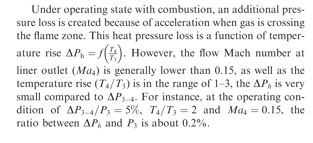
Typical aerodynamic characteristics in an aero-engine combustor are illustrated in Fig. 1. The air flow coming from high pressure compressor pass through pre-diffuser, expand into combustor in three parts, and finally converge in liner chamber:
(1) The first part is the air flowing through the dome swirler.This part plays a key role on the fuel spray and on the formation of recirculation zone for flame stabilization.The pressure loss will be created when air passes through the dome swirler. This pressure loss can be approximately expressed as ΔPdome≈P3-P4, where the P3is the pressure at the pre-diffuser outlet (or combustor inlet pressure), the P4is the pressure at the liner outlet.The dome pressure loss (ΔPdome) is close to the total combustor pressure loss ΔP3-4=P3-P4.
(2) The second part is the air flowing through the outer liner orifices. This part plays important role on outer liner wall cooling. The pressure loss will also be created not only when the air expands from prediffuser into outer ring chamber, but also when the air passes through the outer liner orifices. The pressure loss of the outer expansion can be expressed as ΔP3,32o=P3-P32,o, the pressure loss of the outer liner cooling can be approximately expressed as ΔPliner,o≈P32,o-P4, where the P32,ois the pressure in the outer ring chamber.
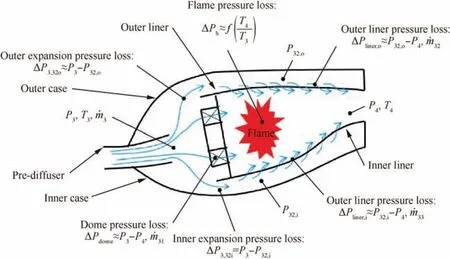
Fig. 1 Typical aerodynamic characteristic in an aero-engine combustor.
(3) The third part is the air flowing through the inner liner orifices.This part plays important role in inner liner wall cooling.The pressure loss of the inner expansion can be expressed as ΔP3,32i=P3-P32,i, the pressure loss of the inner liner cooling can be approximately expressed as ΔPliner,i≈P32,i-P4, where the P32,iis the pressure in the inner ring chamber.
3. Combustor test rig and test items
3.1. Combustor test rig
A simplified combustor test rig sketch is shown in Fig. 2(a).The combustor test rig is composed of inlet pipes, combustor components and exhaust pipes.
The air is fed transversely into the inlet pipes;the total axial length of inlet pipes(L1)is about 7 m.The combustor inlet air mass flow rate( ˙m3)is measured through a throat-tap flow nozzle located upstream of inlet pipes. The combustor inlet air pressure (P3)and temperature(T3)are measured at the downstream of inlet pipes.
The combustor components include: multi-nozzles dome,fuel injectors, liner and ignitor. The axial length of liner (L2)is about 0.2 m. A ‘‘baffle A” with orifices is mounted at upstream of outer chamber to realize the outer expansion pressure loss, ΔP3,32o(see Fig. 1); for the same sake, a ‘‘baffle B”with orifices is to realize the inner expansion pressure loss,ΔP3,32i(see Fig. 1). The outer chamber and inner chamber are separated from inlet pipes chamber by baffle A and baffle B.The flow characteristics through orifices of baffle A or baffle B are checked by steady CFD (Computational Fluid Dynamics) method. The pressure P32,oin outer chamber,P32,iin inner chamber and P4at downstream of liner chamber are measured.
The liner (see Fig. 2(b)) is composed of the up liner, the down liner, the left liner and the right liner. The left chamber and right chamber are connecting with inlet pipes chamber without baffles. That is, the pressure in left chamber or right chamber is the same with the combustor inlet pressure (P3).The pressure drop across the right/left liner is the same with that across the dome (ΔPdome=ΔP3-4).
To monitor the pressure oscillation in liner, there are two dynamic pressure transducers mounted at the same axial position (or x direction) with ignitor. Along azimuthal direction(or z direction),the angle of liner is 120°;the radius of up liner is about 0.3 m;the first dynamic pressure point(Pd1)is located at 20°away from symmetric line;the second dynamic pressure point(Pd2)is located at symmetric line.The dynamic sampling rate is 10 kHz.
Thermocouples are mounted on both up liner and down liner to measure the liner wall temperature distribution along x direction.The normalized positions(x/H)of thermocouples against dome outlet dump surface are shown in Fig. 2(c) and(d), where H is the height of dome.
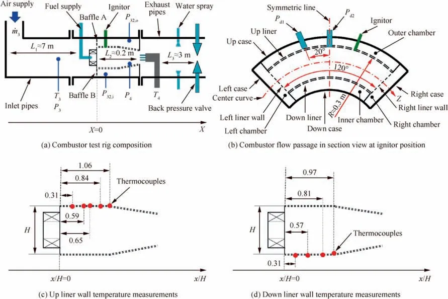
Fig. 2 Simplified combustor test rig sketch and measurements.
The liner outlet temperature (T4) is also measured in the test;the temperature rake is located at the upstream of exhaust pipes.The water is injected into the exhaust pipes to lower the gas temperature before impinging on the back pressure valve.The downstream of back pressure valve is exposed to the atmosphere.
3.2. Test items
Two types of tests are carried out in the investigation: (A)combustor flow resistance tests under non-reacting flow (or cold flow) at atmosphere condition; (B) combustion tests at elevated temperature and pressure.
The combustor flow resistance tests are carried out to obtain the pressure drop properties across each component(such as dome, liner, etc.) and to estimate the corresponding air flow proportions (or air distribution). The test parameters are listed in Table 1. During the flow resistance test, the back pressure valve is thoroughly open so that the outlet pressure(P4) is equal to the atmosphere. The aerodynamic characteristics of combustor under cold flow can be obtained through adjusting the air mass flow rate( ˙m3)and recording the pressure in each chamber.
In combustion tests, the influences of inlet air parameters and fuel air ratio on pressure oscillations are measured. The test conditions (based on the results of flow resistance test)are listed in Table 2.
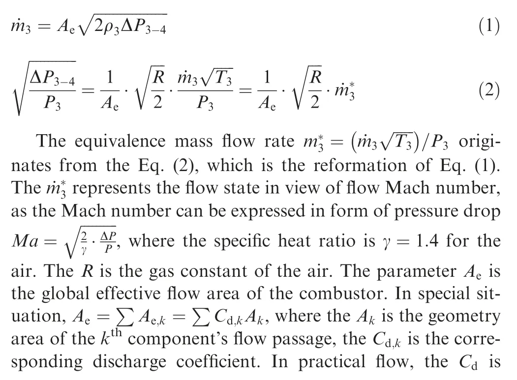

Table 1 Flow resistance test parameters.

Table 2 Combustion test arrangement.
4. Results and discussion
4.1. Aerodynamic characteristics under cold flow
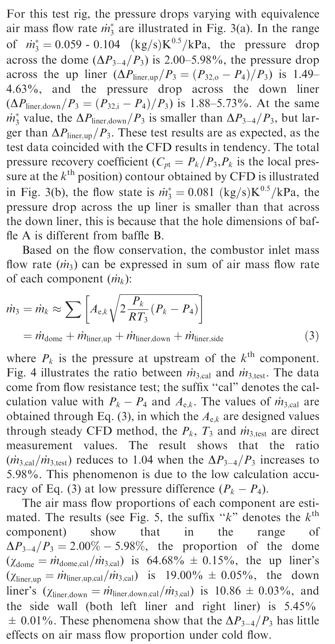
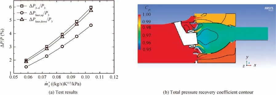
Fig. 3 Pressure drops across combustor components.
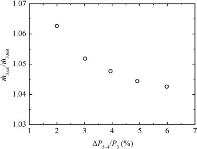
Fig. 4 Comparison of mass flow rate between calculation value and test value.
Based on the flow conservation, the air mass flow rate across the baffle ( ˙mbaffle) is also equal to that across the liner( ˙mliner) in outer chamber or inner chamber (see Fig. 6). The ratios between these two mass flow rates are estimated in Fig. 7. The results show that the ratios reduce to 1.05 (outer chamber)or 1.03(inner chamber)when the ΔP3-4/P3increases to 5.98%. The aerodynamic characteristics presented in Figs.3–5 and Fig.7 are regarded as the base lines(or designed state) for next combustion test analysis.
4.2. Combustion test results
4.2.1. Pressure oscillation characteristics

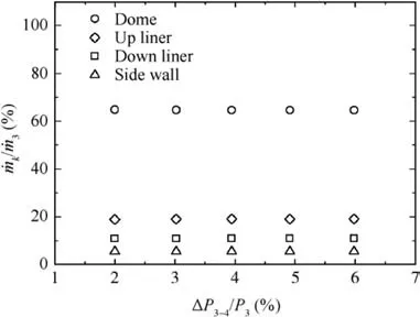
Fig. 5 Air mass flow proportion of each component.
Phase trajectory analysis22,23is applied to understand the nonlinear behavior in an oscillating system and to distinguish the types of pressure oscillation motion. In this study, three kinds of pressure oscillation motions are found:
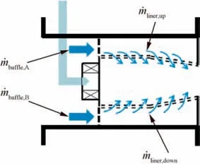
Fig. 6 Air flow at outer chamber and inner chamber.
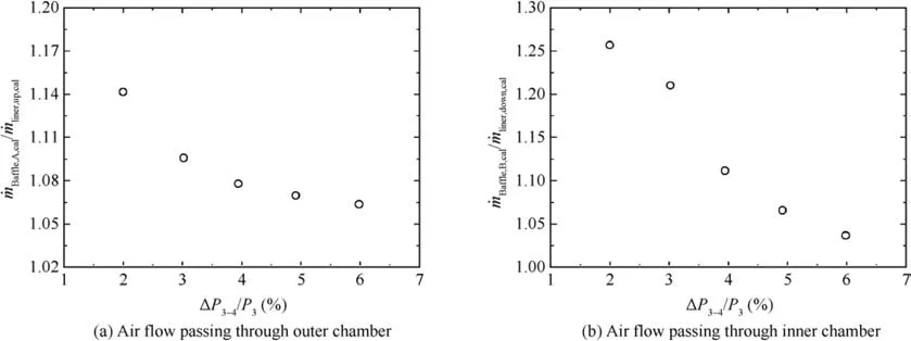
Fig. 7 Ratios of air mass flow rate between baffle and liner.

Fig. 8 Test result contour of operating conditions list in Table 1.
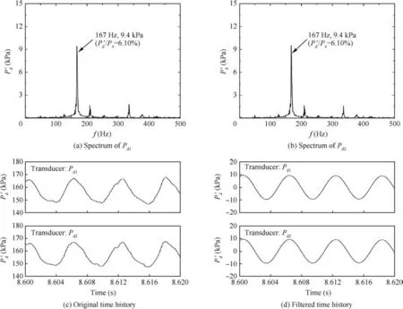
Fig. 9 Dynamic pressure signals.
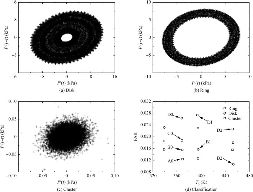
Fig. 10 Dynamic pressure phase trajectory.
(1) Fig. 10(a), ‘‘disk” motion, the trajectory presents a ring structure of which the ring belt width is larger than quarter of the outer diameter of the structure.
(2) Fig. 10(b), ‘‘ring” motion, the trajectory presents a ring structure of which the ring belt width is smaller than quarter of the outer diameter of the structure.
(3) Fig.10(c),‘‘cluster”motion,the trajectory is clustered in a narrow zone.
(4) In above phase trajectory process, band-pass filter of f0±5 Hz is applied to gain the signal.

4.2.2. Aerodynamic characteristics under combustion state
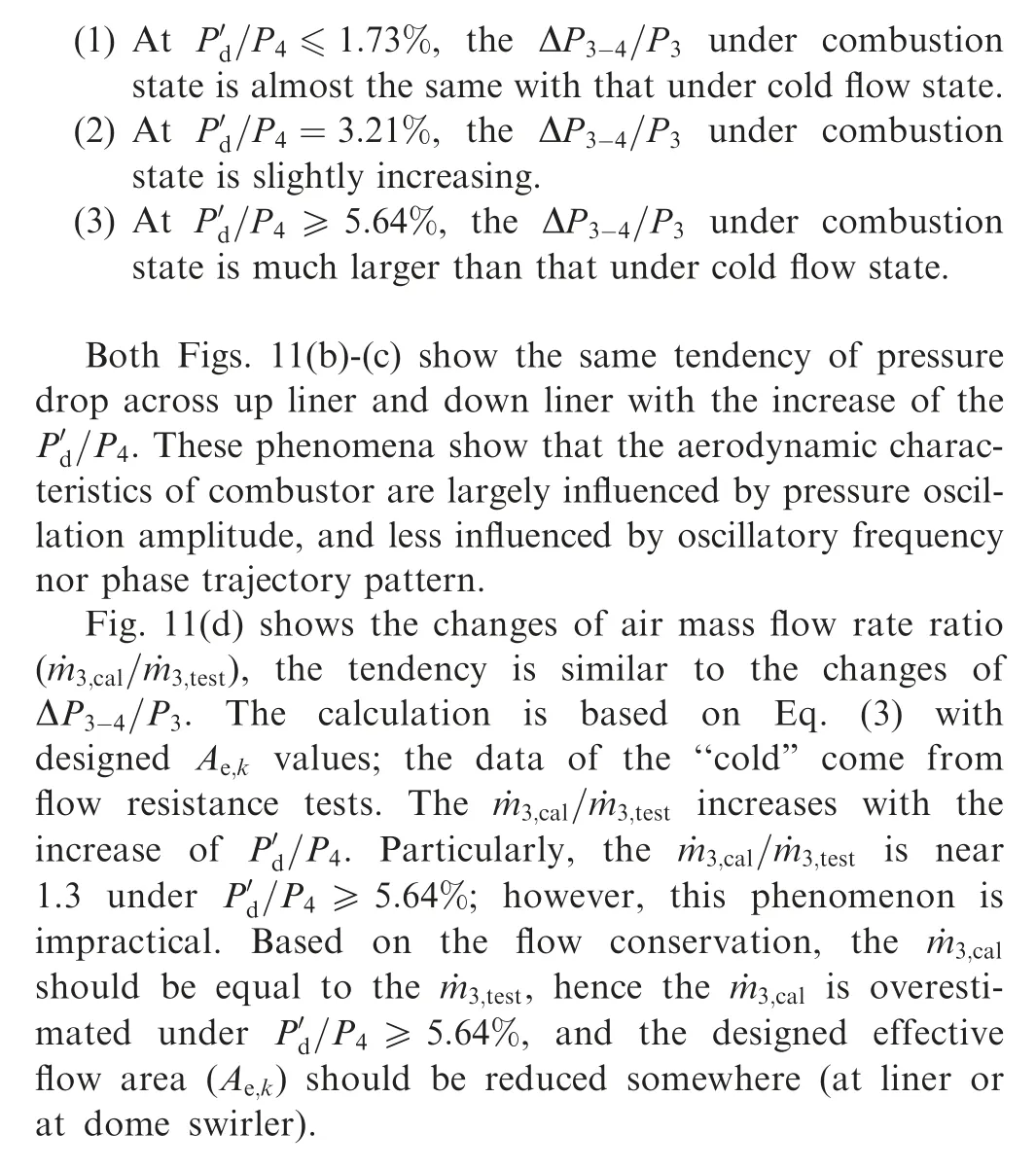
The aerodynamic characteristics of combustor under combustion state are analyzed through comparing with that undercold flow, see Fig. 11. Referred to Table 3, Fig. 11(a) shows that the ΔP3-4/P3present different states with the increase of/P4:

Table 3 Tested parameters of representative operating cases.
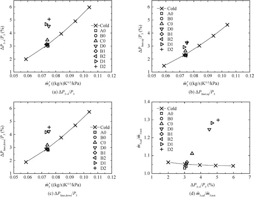
Fig. 11 Comparison of aerodynamic characteristics between combustion state and cold flow state.
4.2.3. Liner cooling flow under combustion state
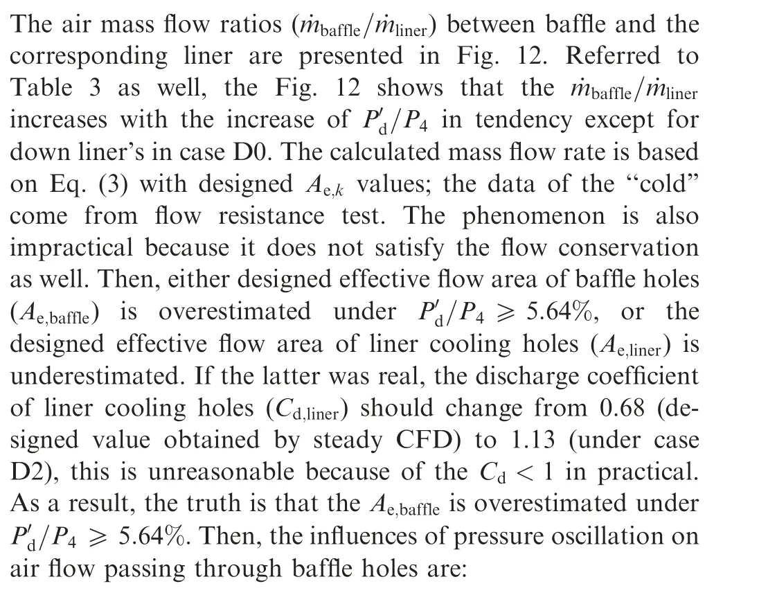
(1) Comparing case group(D0,D1),the reduction degree of Ae,bafflewith‘‘ring”motion is more than that with‘‘disk”motion under the similar pressure oscillation amplitude.
(2) Comparing case group (B1, B2), the oscillation frequency has little effects on Ae,baffleunder the same oscillation amplitude and phase trajectory motion.
(3) Comparing case groups (B0, B1) and (D1, D2), at the same ‘‘ring” motion, the larger oscillation amplitude is,the more reduction of Ae,baffleis.
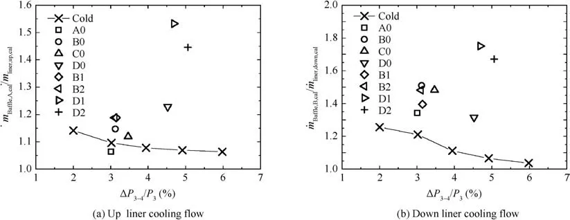
Fig. 12 Comparison of air mass flow ratio between baffle and liner under combustion state.
In general, the pressure oscillation will enhance the turbulent intensity which will reduce Cdand consequently reduce Ae. Then a question is whether the Ae,linerhad been reduced under P′d/P4≥5.64%.The liner wall temperature(Tw)is analyzed to answer the question in the next section.
4.2.4. Liner wall temperature under combustion state
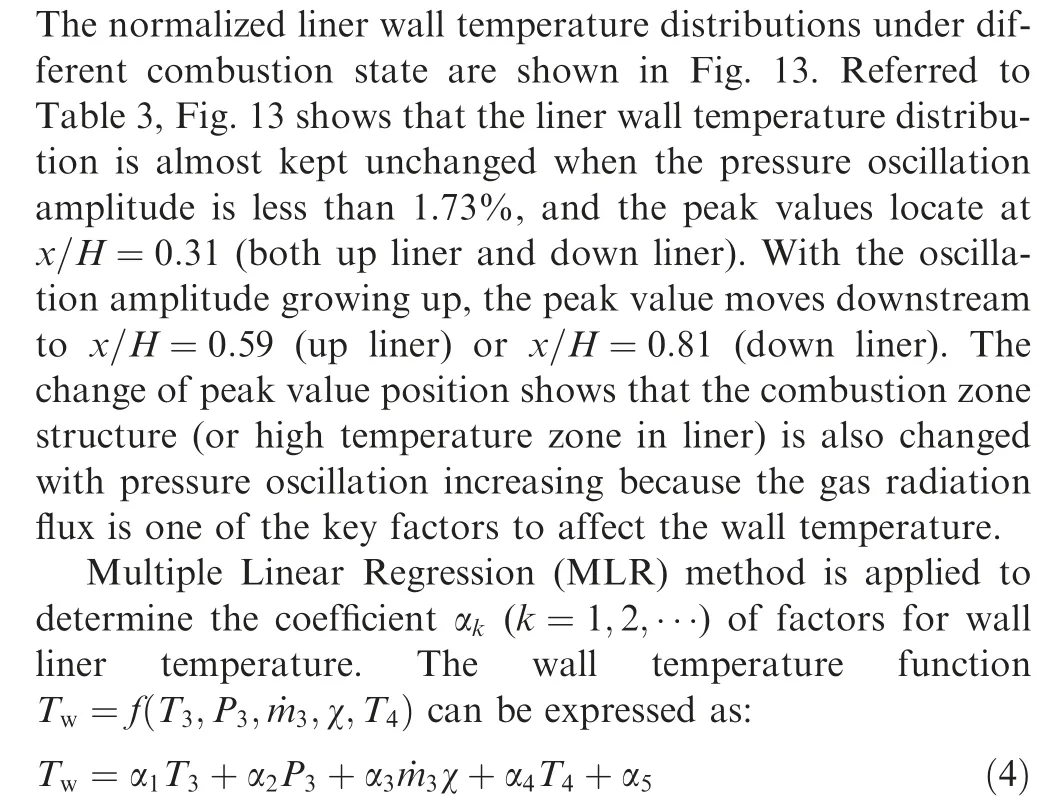
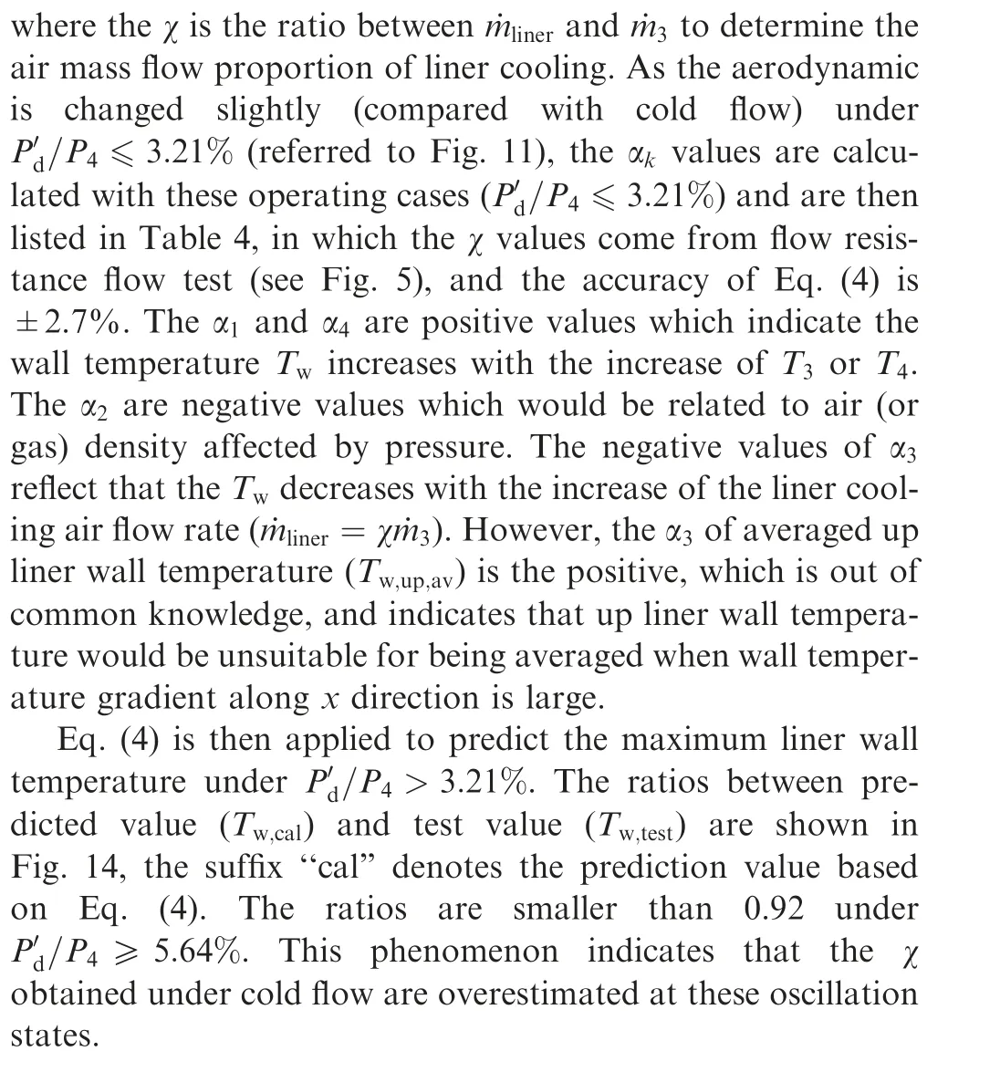
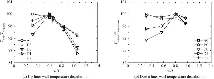
Fig. 13 Normalized liner wall temperature distributions under different combustion state.

Table 4 Weight coefficient of MLR for liner wall temperature.
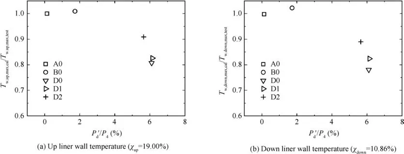
Fig.14 Comparison of liner wall temperature between prediction value and test value.
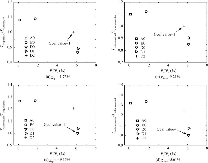
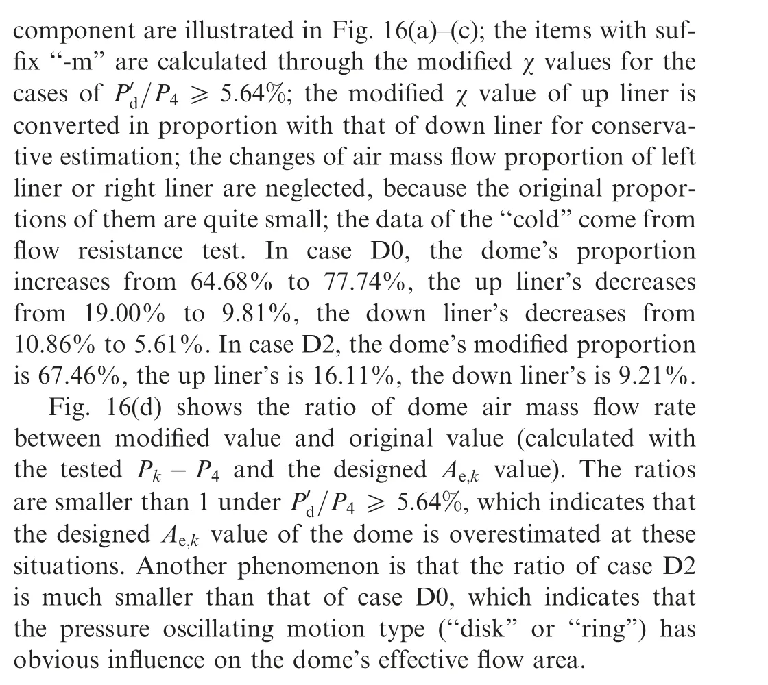
Fig. 15 Comparison of liner wall temperature between modified prediction value and test value.
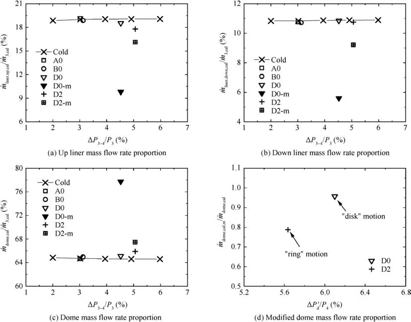
Fig. 16 Comparison of air mass flow proportion between combustion state and cold flow.
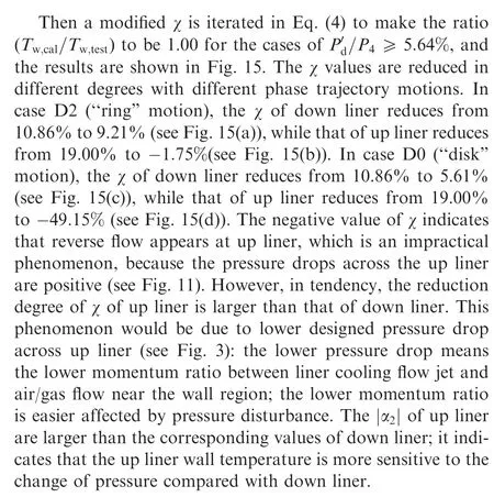
4.2.5. Air mass flow proportion under combustion state

5. Conclusions
(1) The air mass flow rate proportion of each component(dome, up/down liner) keeps unchanged in a broad range of pressure drop ΔP3-4/P3=2.00%–5.98% under cold flow condition.
(2) The pressure oscillation amplitude P′d/P4increases with the increase of FAR. The pressure oscillation motions are classified into three kinds: ‘‘disk”, ‘‘ring” and ‘‘cluster”through phase trajectory reconstruction.The‘‘disk”(case D0)and‘‘ring”(case D1)motion should be related to atomization referred to operating parameters.
(3) The changes of pressure drops across each component are strongly affected by the pressure oscillation amplitude, but are less influenced by pressure oscillation frequency, nor oscillation motion. The pressure drops across each component increase with the increase of P′d/P4. The pressure drop properties under cases of P′d/P4≤3.21% are almost the same with the cold flow,whilst the pressure drop properties under P′d/P4>3.21% are quite different from the cold flow.
(4) The reductions of effective flow area of each component are found under P′d/P4>3.21%,the reduction degree is strongly related to the pressure oscillation amplitude and the oscillation motion.
(5) The air mass flow proportions of each component are also estimated under P′d/P4≥5.64%. The proportions of up liner and down liner are decreasing, and the proportion of dome is increasing. The degrees of these changes are influenced by pressure oscillation motion.
 CHINESE JOURNAL OF AERONAUTICS2021年2期
- CHINESE JOURNAL OF AERONAUTICS的其它文章
- Recent active thermal management technologies for the development of energy-optimized aerospace vehicles in China
- Electrochemical machining of complex components of aero-engines: Developments, trends, and technological advances
- Recent progress of residual stress measurement methods: A review
- Micromanufacturing technologies of compact heat exchangers for hypersonic precooled airbreathing propulsion: A review
- Towards intelligent design optimization: Progress and challenge of design optimization theories and technologies for plastic forming
- A combined technique of Kalman filter, artificial neural network and fuzzy logic for gas turbines and signal fault isolation
