Influence of shock attenuation on tailored operation in free piston shock tunnels
Hao ZHU, Hainan JIANG
China Academy of Aerospace Aerodynamics, Beijing 100074, China
KEYWORDS Attenuation;Constraint equation;Free piston shock tunnel;Real gas effect;Shock wave;Tailored operation
Abstract The free piston shock tunnel is a type of shock tunnel with high performance. For this type of tunnel,the influence mechanism of shock wave attenuation on tailored operation is explored by numerical simulation and theoretical analysis.By introducing the normalized velocity,the simple constraint equation for shock wave under the tailored operation is deduced.Moreover,the real gas effect is also taken into account in this equation. Based on the equation, the tailored operation of shock tunnels can be predicted with very few calculations.The present study shows that the change rate of the thermodynamic state of the gas behind the shock wave is inconsistent with the attenuation rate of the shock wave,which is the fundamental reason why the wind tunnel achieves tailored operation at a lower Mach number of shock waves.This lower Mach number of shock waves differs from the corresponding ideal value by a factor,which is about the square root of shock attenuation rate.
1. Introduction
Free Piston Shock Tunnels(FPSTs)are important facilities for investigation of the high temperature effects such as chemical and thermal relaxation on the aerothermodynamics of entry or re-entry space vehicles.With the development of hypersonic research, free piston shock tunnel has been greatly developed.1,2Refs.3,4 have systematically described and evaluated such shock tunnels. The operation and calibration of FPST are introduced in Refs. 5–7, and relevant experiment studies can be found in Refs.8–11.The structure and running characteristics of FPSTs are liable to cause severe attenuation of shock wave unless the heavy piston keeps a fairly high speed(called over-driving operation) when the diaphragm ruptures.12This running mode of tunnels is called an overdriving operation or tuned operation, and for details, please see Refs. 13,14.
FPSTs generate high enthalpy and high pressure hypersonic flow with useful test time of several millseconds. Thus, prolonging the useful test time of FPST by the tailored operation is very important. The tailored operation is a common operation mode in shock tunnels,which can keep the gas pressure in the nozzle chamber stable and prolong the useful test time of the shock tunnel.15The technique consists in selecting an initial loading pressure in the driver tube for given driven condition so that no downsteam wave is generated when the reflected shock wave interacts with the driver gas contact surface. It means that there mostly exists a proper Mach number of the incident shock wave satisfying the tailored operation.Many results on the tailored operation can be found in Refs.16–21.
Due to various restrictions in the actual operation of free piston shock tunnels, free pistons do not always meet the requirements of over-driving operation,and shock attenuation often occurs.Therefore,it is necessary to study how the shock attenuation affects the tailored operation.Unfortunately,there are very few results about this important question. In this paper, the influence mechanism of shock wave attenuation on the tailored operation is explored by theoretical analysis,and the constraint equation about the shock wave Mach number is obtained. The constraint equation provides convenience for rapid prediction of the tailored operation in shock tunnels.And the present result reveals that the change rate of the thermodynamic state of the gas behind the shock wave is not consistent with the attenuation rate of the shock wave, which results in the wind tunnel reaching the tailored operation at a lower Mach number of shock wave. This research will be helpful to enrich the operation state and improve the operation quality of the free piston wind tunnel.In addition,it should be note that in the process of derivation and calculation, some assumptions and parameter estimation are based on numerical simulation results or shock tube theory.
2. Shock wave attenuation in FPST
In the traditional free piston shock tunnel,when the main diaphragm ruptures, the piston reaches the end of the compression tube and its front face is very close to the main diaphragm. The tube between the piston front face and the main diaphragm is the actual driver section of the wind tunnel,while the shock tube is the driven section. The length of the driver section is very short,usually less than 1/10 of the length of the driven section, see Fig. 1. In Fig. 1, a is the gas sound speed, u is the gas velocity, U is the shock wave velocity, x is the coordinate length from diaphragm, t is the time, L/λ is the length of the driver section,l is the length of the driven section, subscript 1 is denoted the condition ahead of primary shock wave, subscript 2 is denoted the condition behind primary shock wave, subscript 3 is denoted the condition behind contact surface, subscript 4 is denoted the condition in compression tube meanwhile diaphragm opening, subscript 5 is denoted the condition behind reflected shock wave in the test gas,subscript 6 is denoted the condition behind reflected shock wave in the driver gas when the contact surface is tailored,subscript r is denoted the reflected shock wave, subscript rHA is denoted the reflected shock wave in Helium and Argon mixing gas,subscript rr is denoted the reflected shock wave from interface,subscript s is denoted the incident shock wave.This structural feature makes the free piston shock tunnel itself in an awkward situation. In order to maintain the driver gas pressure as much as possible,in this short driver section,the piston must have a fairly high speed. This approach is called overdriving operation.On the other hand,the piston needs to slow down very quickly and achieve a soft landing, so the whole time of constant driver gas pressure is not allowed to be long.This means that driver gas pressure will drop rapidly whether or not over-driving operation is used. Thus, the expansion wave will reflect quickly and will likely catch up with the contact surface and shock wave in the shock tube,resulting in severe attenuation of shock wave, which will also reduce useful test time of the tunnel.
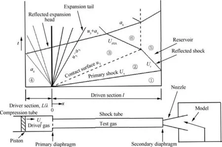
Fig. 1 Distance-time diagram in free piston shock tunnels.
For example, in Shot 2499 of T4 wind tunnel, the shock wave attenuates remarkably, and the piston terminal velocity approaches 89.6 m/s, much lower than the corresponding value of the over-driving operation.22During the calibration of the free piston shock tunnel (FD-21) in China Academy of Aerospace Aerodynamics (CAAA), shock attenuation caused by reflected expansion wave has occurred many times.For example, the record of the pressure sensors in Shot 57 shows that the shock wave has a significant drop near 31 m downstream of the shock tube, where the expansion wave catches up with the shock wave. In this shot, the diaphragm is opened 201 ms after the piston is launched, and at this moment,the piston is traveling at 50 m/s.23The velocity of piston does not meet the requirement of the over-driving operation. In addition, the severe shock attenuation caused by the reflection expansion wave often occurs in the arc-heated shock tunnel.24In fact, the severe shock attenuation is a common problem in a free piston shock tunnel with a very short driver section.
The shock attenuation often occurs in free piston shock tunnel, which has been stimulated in the present study. This situation can be further verified from the following numerical studies(see Table 1 and Fig.2).Table 1 gives two different driver sections, and the corresponding initial velocity and terminal velocity of shock wave. Under No.1 condition, the attenuation of shock wave is only caused by the boundary layer viscosity, while under No.2 condition, the attenuation of shock wave is caused by both the boundary layer viscosity and the reflected expansion wave, and the latter effect is more significant.The gain of shock wave velocity caused by variable cross-section driving is not enough to offset the shock attenuation caused by reflected expansion wave,so that the terminal velocity of shock wave under No.2 condition is still lower than that under No.1 condition. Fig. 2 shows the pressure distribution along the axis of the two shock tubes, and the velocity of the contact surface and shock wave changes with time. Under No.2 condition, the reflected expansion wave catches up with the contact surface, near 2 m downstream of the shock tube.After that, the contact surface and the shock wave almost always decelerate remarkably. Under No.1 condition, the reflected expansion wave does not catch up with the contact surface, so the contact surface kept a slow acceleration and the shock slowed down slowly under the viscous condition.This trend is consistent with the relevant test results in Ref.25. Under these two conditions, the volume of driver gas is the same. This result also implies the advantage of properly extended length of driver section for free piston shock tunnel.Only when the terminal velocity of piston and the length of driver section are both considered carefully, the attenuation of shock wave can be effectively suppressed and the test time be prolonged.Of course,with the concentration of argon increasing, the shock attenuation caused by expansion wave will be suppressed, but the strength of shock wave will also be reduced. These simulations were performed using the axisymmetric shock tube code ST2D. In this code, the flow control equation is an unsteady Navier-Stokes equation based on the structural grid.The HLLC Riemann solver is used to calculate the convection flux. And the Spalart-Allmaras turbulence model is used in the code. In addition, in order to simplify the calculation, the program assumes that the free piston has fully decelerated when it reaches the end of the compression tube,and the free piston speed is far less than the sound speed of the driving gas. In this way, the free piston surface can be regarded as a solid wall. More details about ST2D can be found in Ref. 26.
Due to the existence of a short driver section, the shock attenuation often occurs in the free piston shock tunnel,which has motivated the present research. In the actual operation of shock tunnels, the influence of reflected expansion waves on the stagnation state of the tunnel is intermittent.And the interaction of the transmitted shock wave passing through the contact surface will restrain and delay the influence of the reflected expansion wave quickly. For two reasons, the tailored operation is still available under certain conditions in free piston shock tunnels.
3. Tailored condition
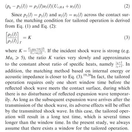
The tailored operation is a common mode in shock tunnels to prolong the useful test time of tunnels. If the incident shock wave is not strong (<2.0 km/s), the driven gas in shock tubes satisfies the hypothesis of perfect gas,and the constraint equation about the Mach number of the incident shock wave for the tailored condition could be obtained easily.21,27If the incident shock wave is strong (≥2.0 km/s), real gas effect of the driven gas in shock tubes will occur distinctly, which changes the tailored operation and makes calculation more complex.The real gas effect should be considered in the tailored operation of free piston shock tunnel. The tactics was provided to get Mach number of shock waves under the tailored operation by iteratively solving shock equations and state equation of the real gas.18However, this method cannot provide the internal constraints that the shock wave needs to be satisfied in the tailored operation. Free piston shock tunnel can be simply regarded as a shock tube with sudden change in cross-section area, so the tailored operation also needs to consider this change.In the real gas case,Reddy supplied a constraint equation about the incident shock wave for the shock tube with constant area.19,28The current research is inspired by his work.If the tailored operation achieves at the end of the shock tube (x=l), the gas pressure in Region ⑤ and ⑥ (see Fig. 1) are equal, namely p6=p5. At the same time, using the conserved relation of the gases at the front and back of the reflected shock, we obtain

where ρ2and u2are respectively the gas density and velocity in Region ②;Uris a reflected shock wave velocity relative to test facility. Similarly, if u6=0, the velocity of the transmitted shock Ur,HAsatisfies

Table 1 Attenuation of shock wave velocity with different driver sections.
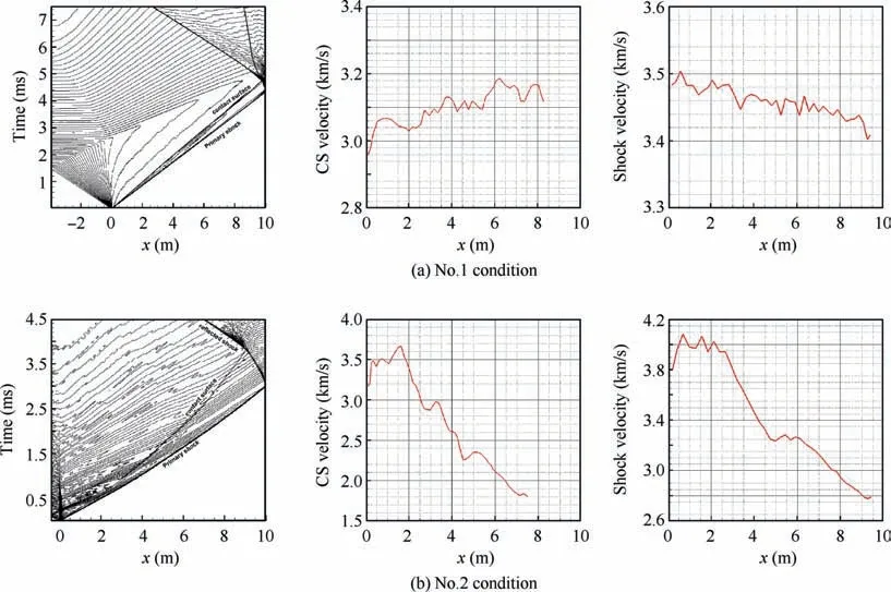
Fig. 2 Pressure distribution, Contact Surface (CS) velocity and shock wave velocity with different driver sections.
4. Normalized velocity with shock attenuation
In FPST, the driver gas is the mixing of helium and argon,while the driven gas (test gas) is air. We use x to denote the moving distance of the shock wave from the diaphragm.Once the initial state of driver gas and driven gas is fixed,the velocity of the shock wave Usonly depends on coordinate x, namely,Us=Us(x). During the attenuation of the shock wave, the state parameters (such as pressure, density, temperature and so on) of the driven gas behind the shock wave will adjust at the same time. With the help of the code ST2D, the evolution of gas state parameters in Region ②and ③(such as temperature, velocity, and density) after shock wave are shown in Fig. 3. In Fig. 3, p3is the gas pressure in Region ③, T2is the temperature in Region ②,T3is the temperature in Region③,ρ2(RH2)is the gas density in Region ②,Usis the primary shock wave velocity. x is the coordinate length from the diaphragm in the tunnel. It can be seen that the dimensionless pressure attenuation is the most severe during shock wave travel,while the density attenuation of gas in Region ②and ③is very limited. In the Fig. 3(a), helium is used as the driver gas.Its sound velocity is large, so the reflected expansion wave speed is fast, and it catches up with the contact surface/shock wave at about 3 m. In the Fig. 3(b), the helium/argon mixture is used as the driver gas. Its sound speed is small, so the reflected expansion wave speed is slow. The position where the reflected expansion wave catches up with the contact surface or shock wave is about 6 m downstream of the shock tube.When the reflected expansion wave and the contact surface/shock wave act on each other, some instability will occur.So, there exists deviation between the attenuation of gas temperature in Region ③and that of shock wave. However, with the shock wave moving and reaching the end of shock tube,the attenuation of temperature in Region ③will be close to that of shock wave. This will be an important assumption used in the following derivation.
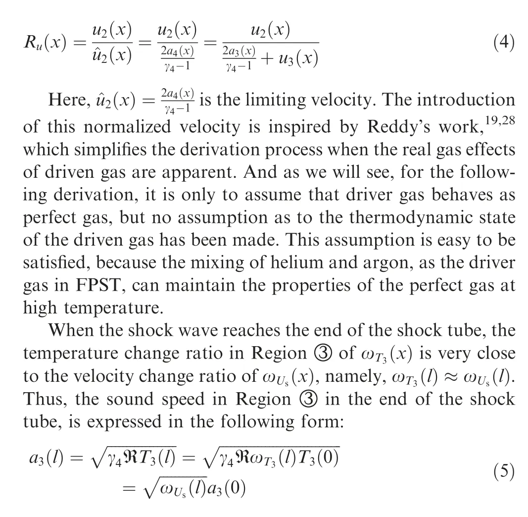
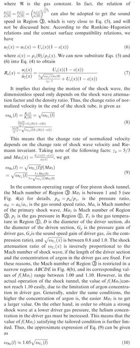
As a reasonable simplification,a free piston shock tunnel is replaced by the shock tube with area abrupt change whose wave diagram (without attenuation) is shown in Fig. 1. And subscripts 1–6 refer to the regions indicated in Fig. 1, while major quantities of Fig.1 could be seen as the function of position x, when the attenuation of shock wave is taken into account.The normalized velocity Ru(x)is introduced primarily by
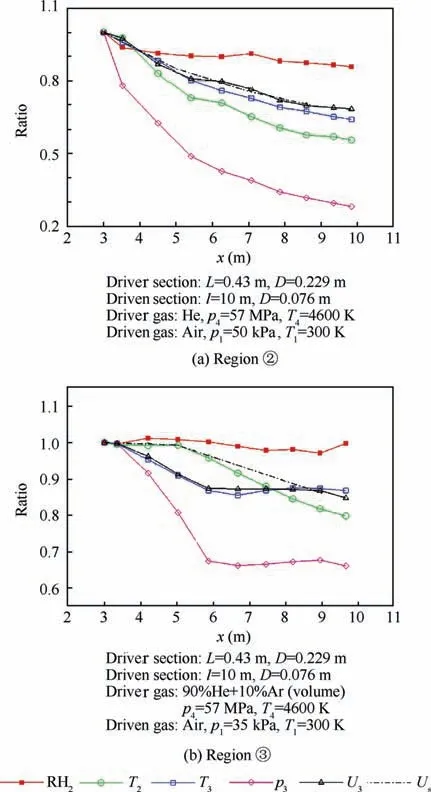
Fig. 3 State parameters ratio of Region ②and ③with shock wave attenuation.
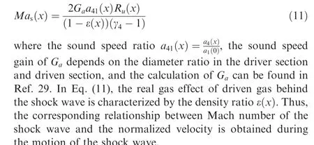
On the other hand,Mach number of the shock wave can be expressed as19
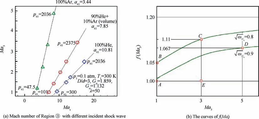
Fig. 4 Mach number of Region ③and corresponding function.
5. Constraint equation for Mach number
In order to obtain the constraint condition about the shock wave under the tailored operation, we need to use Eq. (3).The density ratio of ρ23(l)on the left side of Eq.(3)can be represented as
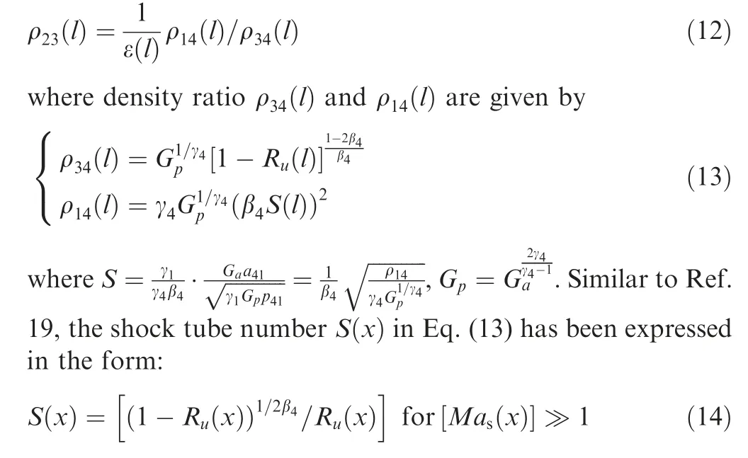
When the real gas effect of driven gas occurs, Eq. (14) still establishes.Using Eqs.(13)and(14),the approximate solution of shock Mach number can be obtained. There is a deviation between this approximate solution and the theoretical value,which decreases with the increase of shock wave Mach number. In particular, when Mach number of shock wave is 8,the deviation is only 0.3%.28As the real gas effect and the shock wave attenuation are taken in account, the matching condition for tailored operation can be obtained easily by this approximate expression of Mach number of shock wave.Substituting Eqs. (12), (13) and (14) into Eq. (3), and eliminatingS(x), we can get

During the attenuation of the strong shock wave, if the movement distance of the shock wave is less than the length with 150 times of the diameter of the shock tube,the variation of the density ratio ε(x) will be very slow, so that ε(l)≈ε(0).Using Eqs. (11) and (15), we finally have the constraint equation about the shock wave in the tailored condition:
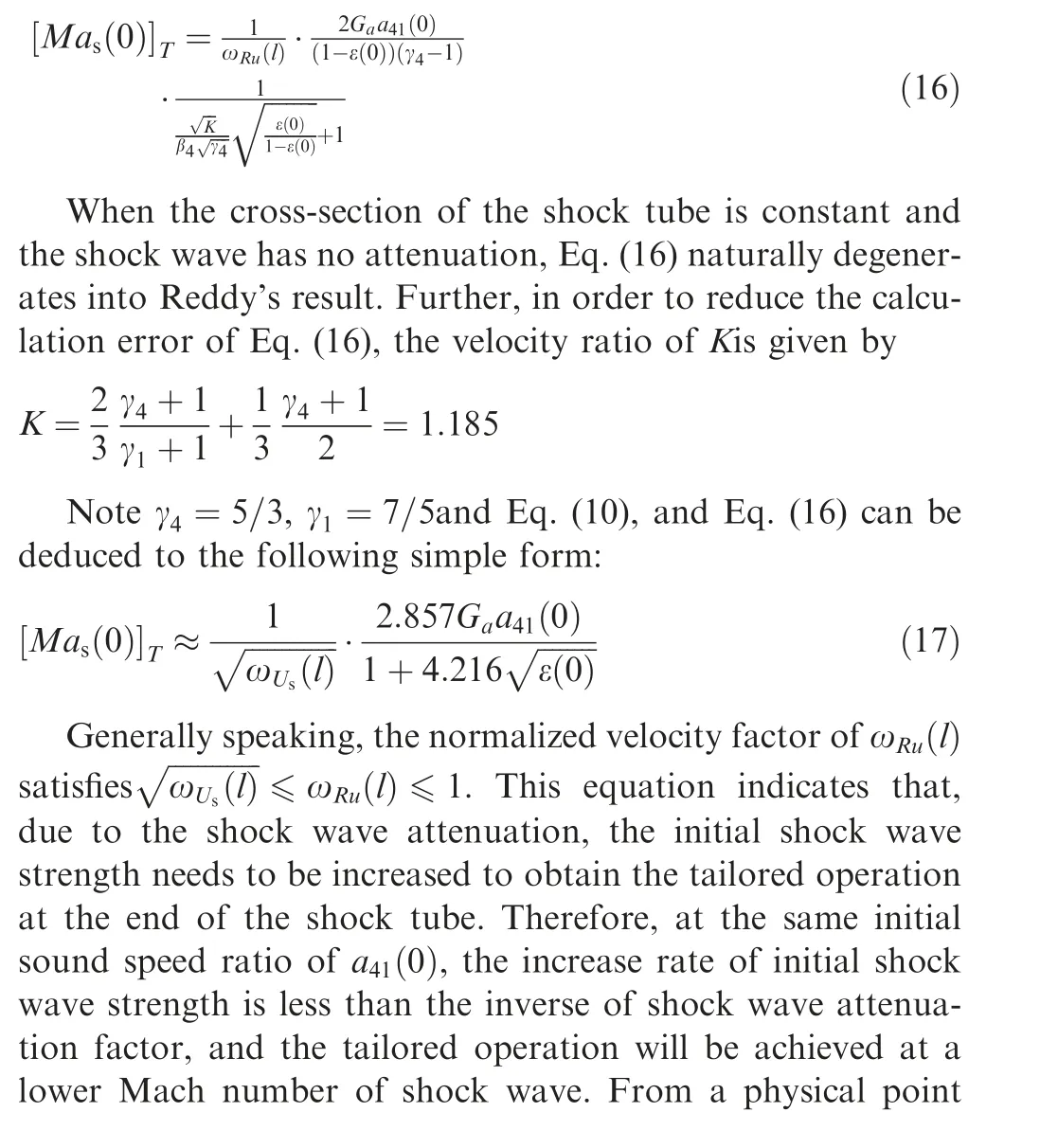
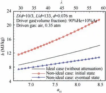
Fig. 5 Enthalpy of shock wave as the function of sound speed ratio under tailored condition.

6. Numerical results
A numerical example will be given for free piston shock tunnels, in which the composition of the driver gas (heliumargon mixing gas)in the compression tube,its initial temperature THA,0and compression ratio λ are preliminarily given.And the initial pressure of the driven gas in the shock tube,p1with its variation range of 0.05–2.0 atm,and its temperature of T1(T1=THA,0=296 K) are also given. At the moment of the first diaphragm burst, the pressure, density, temperature and sound speed of the driver gas, which are corresponding to those parameters in Region ④, could be obtained by the isoentropic compression relation:

The sound speed ratio of a41(0) at the moment of the diaphragm burst is also the function of the compression ratio.During calculation,the shock wave Mach number is estimated by Eq.(10).The density ratio of ε(0)could be iteratively solved by the Rankine-Hugoniot relation, and the Reynolds number behind the shock wave could be also obtained at the same time.
The free piston shock tunnel T4 is used as the numerical experiment bed. Its diameter ratio of the compression tube to the shock tube D/d is 10/3, the ratio of the length to the diameter of the shock tube l/d is 133, and the diameter of the shock tube d is 0.076 m.22In this example, a driver gas is a mixture with 90% helium and 10% argon by volume, pressure of the driven gas p1is 0.35 atm,and the compression ratio of the piston compressor λ varies from 30 to 60. For the tailored operation,we focus on how much the shock wave velocity attenuates at the end of the shock tube,regardless of how it attenuates.It means that we can artificially increase the viscosity to equal the effect of the reflected expansion wave. Thus,the rough approximate expression about the attenuation factor ωUsis used temporarily:
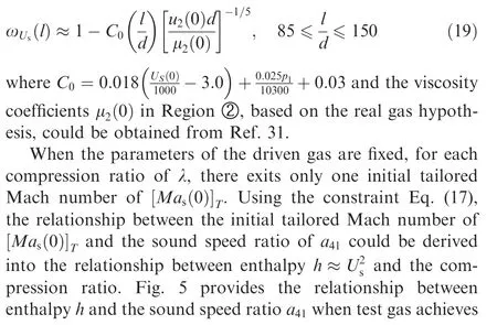

Table 2 Comparison between present results and experimental data in different free piston shock tunnels.
7. Conclusions
Based on the numerical simulation and theoretical analysis,the explicit constraint equation about Mach number of shock wave under the tailored condition is derived. In this equation,both shock wave attenuation and real gas effect are taken into account. The constraint equation provides a more rapid and accurate method to seek the tailored operation for the free piston shock tunnel. The present results reveal for the first time that the wind tunnel will achieve the tailored operation at a lower Mach number of shock waves if the shock wave attenuation exists.The reason for this phenomenon is that during the propagation of shock wave, the change rate of normalized velocity, or the change of acoustic impedance ratio of gases on both sides of the contact surface is not the same with shock wave attenuation. It means that the free piston shock tunnel does not have to raise the driving level too much, such as the pressure or temperature of the driver gas, because of the attenuation of the shock wave.If it is assumed that shock wave has no attenuation, the constraint equation naturally corresponds to the ideal results. And the whole derivation only requires the driver gas to remain the prefect gas state without this limitation for the driven gas. So, these factors make the results of this paper be not limited to free piston shock tunnels.
Declaration of Competing Interest
The authors declare that they have no known competing financial interests or personal relationships that could have appeared to influence the work reported in this paper.
Acknowledgement
This study was supported by the National Natural Science Foundation of China (No. 11572303).
 CHINESE JOURNAL OF AERONAUTICS2021年2期
- CHINESE JOURNAL OF AERONAUTICS的其它文章
- Recent active thermal management technologies for the development of energy-optimized aerospace vehicles in China
- Electrochemical machining of complex components of aero-engines: Developments, trends, and technological advances
- Recent progress of residual stress measurement methods: A review
- Micromanufacturing technologies of compact heat exchangers for hypersonic precooled airbreathing propulsion: A review
- Towards intelligent design optimization: Progress and challenge of design optimization theories and technologies for plastic forming
- A combined technique of Kalman filter, artificial neural network and fuzzy logic for gas turbines and signal fault isolation
