A fatigue damage-cumulative model in peridynamics
Bincho LIU, Rui BAO,*, Fucheng SUI
a Institute of Solid Mechanics, School of Aeronautic Science and Engineeing, Beihang University, Beijing 100083, China
b Shenyang Aircraft Design and Research Institute, Shenyang 110801, China
KEYWORDS Fatigue crack growth rate;Fatigue damage;Fatigue element model;Fatigue lifetime;Multiple site damage;Peridynamics
Abstract While the present structural integrity evaluation method is based on the philosophy of assumed similitude, Fatigue and Damage Tolerance (F&DT) evaluations for next generation of air-vehicles require high-fidelity physical models within cyberspace.To serve the needs of F&DT evaluation in digital twin paradigm,a fatigue damage-cumulative model within peridynamic framework is proposed in this paper.Based on the concept of fatigue element block and damage accumulation law in form of Coffin-Manson relationship,the proposed model applies to both fatigue crack initiation and fatigue crack growth; fatigue crack growth rates under constant-amplitude and simple variable-amplitude block loading cases can be well predicted for three common structural materials without inputs of Paris law parameters.Additionally,the proposed model can also be easily extended to a probabilistic version;for verification,multiple-site-damage problems are simulated and the statistic nature of fatigue process in experiments can be well captured.In the end,main features of the proposed model are summarized,and distinctions from the other models are discussed.There may be a potential for the peridynamic damage-cumulative model proposed in this work to numerically predict fatigue problems in digital twin paradigm for future generations of aerospace vehicles.
1. Introduction
The present Fatigue and Damage Tolerance (F&DT) evaluation method is based on the philosophy of assumed similitude,in which corresponding fatigue properties in in-service components and structures are predicted by specimen data obtained in laboratories under the same service conditions.1Thus, the present F&DT evaluation method is essentially established on an experiment-based philosophy. However, future generations of aerospace vehicles will certainly require lighter mass while being subjected to higher loads and more extreme service conditions,also over longer time periods with higher accuracy and higher reliability;besides,complex service conditions such as loads, environments, multi-scale and multi-physics effects are difficult to reproduce in laboratory experiments.2Accordingly, the philosophy of digital twin has been considered as future development of fatigue discipline,in which F&DT evaluations are mainly conducted in cyberspace with integrated physical models.3Therefore, compared with the present F&DT evaluation method, the future one will be no longer based on experiments but put more emphasis on combinations of experiments and numerical simulations.
Hence, although it is acknowledged that the digital twin philosophy possesses the capabilities of achieving leapfrog developments in the aviation industry, there exist natural philosophy gaps between the present and the future F&DT evaluation methods.4In the blueprint of digital twin philosophy,for example, fatigue behaviors should be predicted by models based on physical nature rather than phenomenological or empirical formulations;as a result,modifications and improvements should be made on the basis of the present methods such as S-N curves and Paris law. The high-fidelity models, which should be applicable to wide range of fatigue problems, are supposed to include proper fatigue parameters as well as corresponding damage accumulation law. For example, some scholars argued that Fatigue Crack Growth (FCG) is plasticity-driven in nature, and stress intensity factor range is thus inadequate to characterize Fatigue Crack Growth Rates(FCGRs) for it is a Linear Elastic Fracture Mechanics(LEFM) parameter5; this argument is especially reasonable in variable-amplitude loading and spectrum loading cases.Under such circumstances, Non-Linear Parameters (NLP)including the range of cyclic plastic strain,6the size of reversed plastic zone,7the total plastic dissipation per cycle,8and the Crack Tip Opening Displacement (CTOD),9are proposed to replace stress intensity factor range and better predictions of FCGRs can be obtained. Moreover, some scholars hoped to simulate specific fatigue phenomena from more physical perspective and have thus proposed damage-cumulative models.10In a recent work,Ritchie and co-workers11have chosen plastic dissipation energy as the driven parameter to predict Paris law parameters, with a nodal release technique to characterize crack propagation as well as the Coffin–Manson relationship to define a damage-cumulative model; the proposed model has successfully predicted FCGRs in steel. Besides, microscale and mesoscale researches aimed at revealing microstructure effects on fatigue damage evolutions are also extensively conducted.12
On the other hand, powerful numerical tools for simulations are indispensable, which have been promoted due to the rapid developments of computational mechanics for decades.The most commonly used tool is undoubtedly Finite Element Method (FEM) and its extensions such as eXtended Finite Element Method (XFEM). Nevertheless, FEM is based on the classical continuum theory, which assumes that the body remains continuous as it deforms; once a crack initiates and propagates, such assumption is violated. From the standpoint of mathematics,the classical continuum theory is formulated using spatial partial differential equations, and these spatial derivatives lose their meanings at discontinuities where cracks occur13;as a result,FEM-based methods demand external criteria for crack propagation or encounter various problems in further applications.14,15In addition to FEM,Molecular Dynamics(MD)have also been adopted to simulate FCG with varying success16; however, the limited time and spatial scales make it applicable to explain mechanism from atomic level, but incompetent to predict crack growth behaviors in practical structures.17,18Under this background, Peridynamics (PD) has aroused intense scholarly interest since its birth and becomes a promising method to study crack propagation.19It attempts to unify the mechanics of continuous and discontinuous media within the same framework in which the spatial derivatives are replaced by integrals,so that the peridynamic governing equations are applicable at fractures and external crack growth criteria are no longer necessary. Peridynamics has been adopted to study dynamic brittle fracture,20,21failure in fiber-reinforced composites,22,23damage in functionally graded materials,24,25and crack path in polycrystal materials.26,27So far, two main peridynamic models for fatigue cracking28,29have been proposed and adopted for some simple applications in preliminary researches.30–32
Despite the above achieved success,however,there is still a long way to go because of our limited understanding of intricated fatigue fundamentals. One typical example may be that Fatigue Crack Initiation (FCI) and FCG are temporarily explained with separate theories despite they are governed by the same physical fundamentals,33and there are neither clear interconnections between theories for these two kinds of fatigue problems partly due to the ambiguous definition of crack initiation as well as vague knowledge of short crack growth.This problem becomes more severe as material science rapidly develops and new techniques such as additive manufacturing blooms.34Furthermore, statistic nature of fatigue33has not been well incorporated into descriptions within the present theories, and the temporary engineering way to deal with dispersion is also separate from present theories;however,according to the demand of digital twin paradigm,3statistical assessments must be part of an overall best-physics approach that is relevant to each individual vehicle.35–37From the aspect of computational mechanics, the huge computation costs in fatigue simulations and non-convergence problems when plasticity involved also need resolutions. Briefly speaking, highfidelity models for fatigue problems are still lacking or in their infancy,due to both the complexity of underlying mechanisms and the challenges in numerical simulations.
Hence, predictive fatigue models towards more physicsbased perspective are needed, which are aimed at serving the needs in future F&DT evaluations required by digital twin philosophy. In this work, a fatigue damage-cumulative model within peridynamic framework is proposed. The proposed model applies to both FCI and FCG, and is also extended to a probabilistic version; FCGRs and Multiple Site Damage(MSD) are respectively simulated for verification and compared with corresponding experiment results.The whole paper is organized as following. In Section 2, the original peridynamic theory is briefly introduced, based on which a peridynamic damage-cumulative model is then proposed. In Section 3, the proposed model is verified by several numerical examples predictions of FCGRs and MSD; simulation results are compared with experiment data and observations. In the end, the features of proposed model are summarized and distinctions from other models are discussed in Section 4.
2. Peridynamic model formulation
In this section we firstly introduce the basic idea of peridynamics fundamentals.38,39Based on peridynamics fundamentals,we propose our fatigue damage-cumulative model with degradation law for Critical Bond Stretch (CBS).
2.1. Peridynamics fundamentals
Assume that an object occupies a certain spatial domain R in the reference configuration at time t. According to the Newton’s second law, the peridynamic equation of motion for a unit volume centered at material point x in the reference configuration is written as
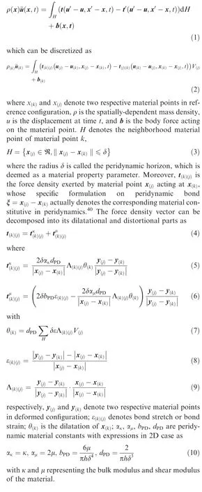
As mentioned above, what makes peridynamics unique beyond FEM lies in its capability of including discontinuities such as damage and cracks.Damage in peridynamics is usually characterized by irreversible bond breakage; many types of bond breakage criteria are available, among which the most intuitionistic criterion is that a bond ξ=xbreaks when its bond strainexceeds the critical stretch ε*, and the critical stretch in 2D case can be expressed as
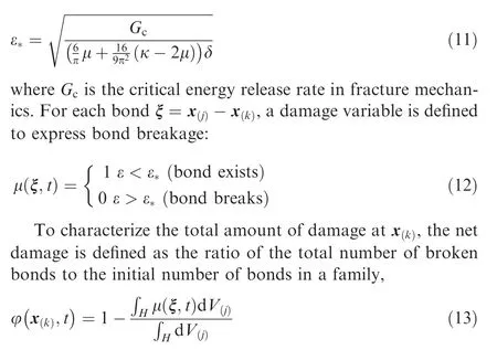
when it reaches critical value φ*, it is regarded that crack occurs on this material point. Parameter studies have pointed out that simulation results are most accurate with δ = 3.015dx where dx is the uniform spacing size of PD material points;from the viewpoint of parameter analysis,it is actually δ = 3dx and the extra 0.015dx is to prevent the position truncation error of material point.41Corresponding to uniform mesh with δ = 3.015dx, the critical net damage value for bulk material points is correspondingly φ*≈0.39.
So far, the peridynamics fundamentals have been introduced briefly. For the purpose of this paper, which is to propose a damage-cumulative model for fatigue cracking in the peridynamic framework,the material constitute should possess the capabilities of describing plasticity and be calibrated to cyclic constitutive law. It should also be pointed out that the selection of an appropriate material constitutive is a tradeoff between accuracy and complexity,42and the stable cyclic constitutive is thus adopted for simplicity in this paper for the following two reasons: on one hand, the cyclic response for common structural metals will be stabilized in dozens of cycles,43which is only a small part if compared with the whole cycle number, and the error of such approximation can be omitted in such case;on the other hand,the computation costs will surge if the exact cyclic response is taken into consideration, and become thus unaffordable when the whole fatigue process is considered.11With a more refined description of cyclic constitutive, it is supposed to predict more accurate results,44but this is not the critical points of this paper.
Therefore,a peridynamic elastoplastic material constitutive model with an isotropic hardening rule using a bi-linear diagram is adopted in this work, whose detailed derivation is omitted here due to limited length of the paper.36Since we found nowhere the open-source code for the above model, a simple validation for stabilized cyclic response of Ti-6Al-4V,which is also one type of the materials for numerical verification in Section 3, is shown in Fig. 1, and the results show clearly that the stabilized cyclic response can be well described.
2.2. Degradation law for fatigue damage
What distinguishes the peridynamic models for fatigue cracking from other peridyanmic models for dynamic cracking is the degradation law for fatigue damage; with undergoing cycles,certain material properties deteriorate which finally lead to FCI and FCG.45In this paper,the peridynamic CBS is considered to be degraded by fatigue damage, and a degradation law in Coffin-Manson formulation is adopted. The basic idea of the proposed model is similar to element block concept.46,47It is intrinsically convenient to incorporate fatigue element model into peridynamics as shown in Fig. 2, where a compact tension C(T) specimen with concentrated force loading P is taken as an example. Fatigue elements possess the same properties and will thus be broken after the same load cycles as the standard smooth specimens; as a result, FCG process is considered as a successive failure process of elementary blocks at the crack tip.
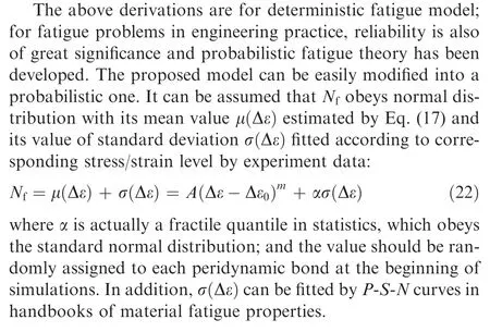
As the material undergoes cyclic loading, the critical bond strain degrades and the bond will break if the bond strain under maximum load exceeds the degraded critical bond strain. The bond strains at two extremes of cyclic load can be defined as
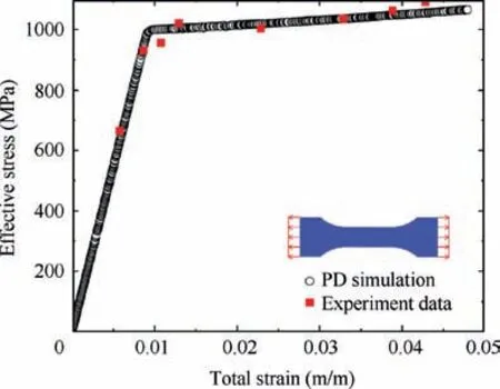
Fig. 1 Validation of material constitutive model adopted in this paper for stabilized cyclic response of Ti-6Al-4V.

According to the fatigue element block model in Fig. 2,peridynamic bond possesses the same fatigue property as material fatigue property obtained by standard smooth specimen,thus the bond lifetime Nfundergoing cyclic loadingis the same as that obtained by standard smooth specimen in experiments, which can be estimated by Coffin-Manson relationship,10
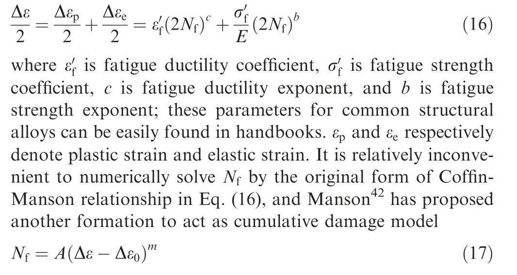
where Δε0is an endurance limit strain which can be approximately estimated as Δε0=Δσ0/E, and Δσ0is endurance limit stress; it is assumed that lifetime is taken as infinite below Δε0.A and m are coefficient and exponent fitted from test data.
Formulation as Eq. (17) has following two advantages.Firstly, both High-Cycle-Fatigue (HCF) regime and Low-Cycle-Fatigue (LCF) regime can be described with satisfying accuracy by such a formulation;thus,the degradation amount for bonds can be expediently estimated no matter they are undergoing large deformation or small deformation. It should be noted that Eq.(17)has been validated as the alternate relation of Coffin-Manson relationship by Manson48himself and also acknowledged by some other researchers.49,50Secondly,cyclic lifetime is expressed in terms of the total strain range other than plastic strain. The accurate calculation of plastic strain requires a super-fine mesh around crack tip and even a complex cyclic constitutive to characterize material response,both of which will largely increase computational costs. Considering the main purpose of this paper as well as for simplicity, Eq. (17) is considered to be proper here.
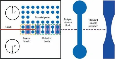
Fig. 2 Schematics of fatigue element block.
Since Eqs. (16) and (17) are equivalent, there must exist some relationships between their parameters. As stated by Manson48, A and m in Eq. (17) are respectively expected to be of the order of coefficient and exponent of plastic strain relation in Eq. (16). When plastic strain is large and elastic strain can be neglected, Eqs. (16) and (17) can be respectively rewritten as
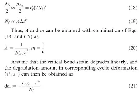
where ε*,0is the critical stretch when material experiences no load cycle and can be obtained by Eq. (11); Nfis obtained according to Eq. (17).
2.3. Cyclic load ratio effects
It has been noted above that A and m are respectively expected to accord with the coefficient and exponent of plastic strain relation in the Coffin-Manson relationship; however, the parameters in Coffin-Manson relationship is usually measured with the cyclic load ratio R=-1, i.e. symmetry cyclic load.Since it is unpractical to measure parameters A and m under every cyclic load ratio and then input them into the computational model, a method to matching total bond strain ranges under arbitrary cyclic load ratio with their counterparts of the same cyclic lifetime under R=-1 is necessary.
Here, the equivalent strain method with a material parameter is adopted in this paper to consider cyclic load effects.51The equivalent total strain range under R=-1 of arbitrary cyclic load ratio is
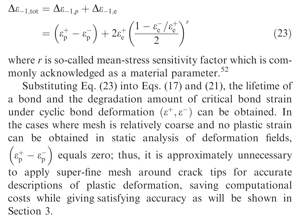
2.4. Numerical implementation
The peridynamic fatigue model is implemented based on a Fortran code, and results are visualized using a visualization software OVITO. As shown in a flowchart in Fig. 3, peridynamic simulations for fatigue cracking start from model preparation (mesh generation, family search, boundary condition application,etc.),and consist of quasi-static solution,degradation of critical bond stretch, computation of skip-cycles Nskipas well as cycle number N,and updating of damage value;surface corrections are also taken into consideration.53
Static analysis is the basis of peridynamic fatigue simulation.54Most published studies on peridynamics focus on the simulations of dynamic crack propagation,and adopt an explicit central difference time integration which requires a conservative timestep to ensure numerical stability. Such stable time step is usually smaller than microsecond level, which makes it prohibitively costly in simulations for fatigue cracking. Therefore, an implicit solver is indispensable for fatigue cracking simulations, and the Adaptive Dynamic Relaxation (ADR)method proposed by Kilic and Madenci54is hereby adopted for all simulations in this paper.
Besides static analysis, the whole fatigue process has to experience hundreds of thousands of cycles, which also costs huge computational resources if the whole process is performed cycle by cycle. In this model the whole deformation fields will not be changed unless there are bonds breaking,thus the cycle number to the next bond breakage Nskipcan be obtained according to the current deformation, and then the degradation amount can be easily obtained without repeating the same static analysis;when the bond breaks,however,static analysis must not be skipped and a new static analysis should be conducted to obtain the updated deformation field.In light of this,the size of PD material points dx may has an impact on simulation results;therefore,convergence studies are necessary and δ-convergence numerical examples will thus be performed.55
3. Numerical examples
In this section,numerical verifications for the proposed peridynamic fatigue model are performed.
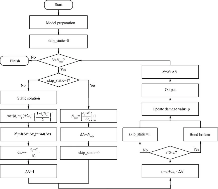
Fig. 3 Flowchart of the proposed peridynamic damage-cumulative model.
In Section 3.1, the predictions for specimen lifetimes are presented for aluminum alloy 2024-T3 under Constant Amplitude (CA) cyclic loading with two cyclic ratios, which are to prove the validity of the idea and formulations adopted in the proposed model. However, FCI phase is not our focus because we have already taken strain-lifetime curves as input,thus the obtained results should not be of predictive sense but the confirmatory one; the key features of this proposed model are emphasized in following two parallel Sections 3.2 and 3.3.
In Section 3.2, the predictions for FCGRs in a simplified compact tension C(T)specimen are presented,and the simulation results are compared with experiment data in authoritative manuals or handbooks of fatigue properties; CA loading and simple Variable Amplitude (VA) loading cases with two blocks of different cyclic load ratios are simulated. Since we have taken no Paris law parameters in simulating FCGRs,the obtained results should be of predictive sense.
In Section 3.3,in order to demonstrate the capabilities of our proposed model of predicting complex fatigue problems, we show the examples of MSD in a three-similar-detail plate and compare the simulation results with experiment observations;the chosen material is aluminum alloy 2024-T3. Stochasticity in Widespread Fatigue Damage (WFD) problems can be well captured by the probabilistic extension of proposed model.
The key material properties in the simulations are listed in Table 1. 52,56
3.1. Specimen lifetimes
For calculating lifetimes, we adopt standard smooth plate specimen and the material is aluminum alloy 2024-T3;CA cyclic loading cases with two cyclic ratios R=0.02 and R=0.6 are simulated, and the obtained specimen lifetimes are shown as Fig. 4. Peridynamic simulation results agree well with the high-cycle-fatigue experiment data in material property handbook.50It should be pointed out that the previous peridynaimic fatigue model proposed by Silling44can also give good results of lifetime calculation, but it is questionable for his model to deal with arbitrary positive cyclic load ratio.The good accordance in Fig. 4 confirms the verification of the proposed model.
3.2. Fatigue crack growth rates
For predicting FCGRs, we adopt a simplified C(T) specimen shown as Fig.5 to substitute traditional C(T)specimen.Compared with traditional C(T) specimen, the loadings in such asimplified C(T) specimen are more friendly about convergence when plasticity is involved in material constitutive. The Stress Intensity Factor (SIF) versus crack length of this simplified C(T) specimen is calculated according to handbooks; it can be seen from Fig. 5 that simplified C(T) specimen is a reasonable substitute for traditional C(T) specimen.

Table 1 Material properties in peridynamic simulations.

Fig. 4 Verifications of the proposed model for predicting fatigue lifetimes.
FCGRs in several materials including 2024-T3, Ti-6Al-4 V and 300 M under CA loading cases are predicted by the proposed model, and the magnitudes of cyclic loads are applied according to corresponding experiment settings for a proper scope of stress intensity factor range ΔK. For each kind of materials, two cases of cyclic load ratios covering a relatively wide range are simulated: R=0.1 and R=0.5 for 2024-T3;R=0.1 and R=0.6 for Ti-6Al-4 V; R=0.05 and R=0.5 for 300 M. The cyclic load ratio is considered in the form of equivalent strain as shown in Eq.(23),and the mean-stress sensitivity factors are listed in Table.52The spacing of PD material points is set as dx=0.8 mm, and δ-convergence studies of dx=0.4 mm are performed especially for 2024-T3. The numerical predictions for FCGRs are presented as da/dN-ΔK curves in Fig. 6, which are in good accordance with experiment data for all listed materials,56,57and the proposed model successfully takes cyclic load ratio into consideration in FCGR predictions. Such results indicate that the proposed model is able to predict FCGRs under CA loading cases for wide range of positive cyclic load ratios in various kinds of materials.
With the successful predictions of cyclic load ratio cases,FCGRs in 2024-T3 under simple VA loading cases with two blocks of different cyclic load ratios are predicted by the proposed model, in which the maximum applied load keeps unchanged while the cyclic load ratios are respectively R=0.1 and R=0.5. The spacing of PD material points is set as dx=0.8 mm.The transition of blocks takes place when the crack length reaches a=16 mm.As is shown in Fig.7,the numerical predictions agree well with NASGRO prediction,57which indicates that the proposed model has the potential to predict FCGRs under such simple VA loading. However, the applicability of the model in complex VA loading or even spectrum loading cases should be conducted with more accurate description of plasticity, more refined modelling and larger computing scale, all of which need further studies.
It is worth noting that no parameters involving the Paris law or other description model for FCGRs appear in the above derivation, which assures that FCGRs are totally predicted rather than calculated with input of Paris law parameters; in other words,the proposed model predicts Paris law parameters rather than adopts them. This is one of the main advantages for our proposed peridynamic fatigue model. With such a distinctive feature,the proposed model can be utilized in simulating FCGRs with complex microstructure distributions such as additively manufactured metals in which Paris law parameters are affected by various microstructures and difficult to measure, and also with complex geometries in which stress intensity factor range is difficult to calculate. Authors have adopted the proposed model to predict phase interface effects on FCG behaviors in additively manufactured Ti–5Al–5Mo–5V–1Cr–1Fe.58
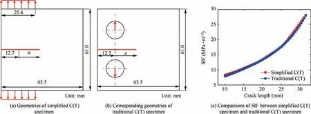
Fig. 5 Verifications of the simplification for specimen modelling.

Fig. 6 Verifications of the proposed model for predicting FCGRs under CA loading.
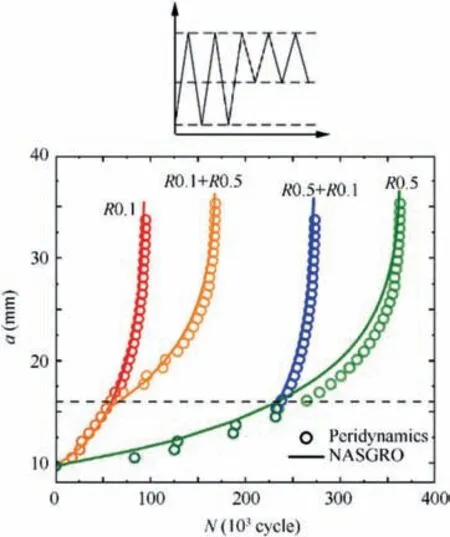
Fig. 7 FCGRs predicted by peridynamic simulations and NASGRRO under simple VA loading cases with two blocks of different cyclic load ratios.
3.3. Multiple site damage
The Aloha accident of B737-200 airplane in 1988 has reminded the fatigue community of WFD problems; as a typical type of WFD, MSD has attracted extensive attention since then.59According to its probabilistic nature, most of the present prediction methods towards MSD are based on probabilistic theory.60In this section, three-similar-detail plates made of aluminum alloy 2024 are simulated to demonstrate the capabilities of proposed peridynamic fatigue model,whose geometries is shown as Fig. 8 with spacing of PD material points dx=0.6 mm.
As stated in Section 2.2, probabilities are incorperated into the model by Eq.(22),in which σfor 2024-T3 can be fitted according to P-S-N curves56:

The results predicted by deterministic model are shown in Fig. 9 as the control group, and the whole process conforms to requirement of symmetry strictly. For initiation process in Figs. 9(a)–(c), it can be seen that cracks initiate firstly at two sides of middle hole (spot 3 and spot 4), then at inside spots of side holes (spot 2 and spot 5), and finally at outside spots of side holes(spot 1 and spot 6).This is due to the corresponding deformation level at each spot decided by plate geometries;a small deviation in local deformation will result in obvious deviations in initiation cycles. For the following crack growth process in Fig. 9(d), the FCGRs of each crack are similar to each other, and thus the crack lengths are also almost the same.
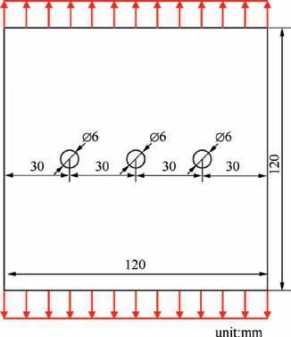
Fig. 8 Modelling geometries of the three-similar-detail plates.
To consider simulation results by probabilistic model as fully as possible, we have conducted 50 different simulation examples with randomly assigned α distribution;for simplicity,we briefly record Example 05 as E05,and so on.Typical crack initiation cases are shown in Fig. 10. Generally, in most cases the cracks tend to initiate from the middle hole which is similar to that predicted by deterministic model in Figs. 10(a)–(c),which is decided by the geometries as mentioned above.However,in some cases cracks at two sides of the middle hole may grow longer while no cracks initiate at the other two holes, as shown in Fig.10(a).And sometimes crack only initiates at one side of middle hole and for the other side crack occurs much later, which accords well with universe MSD experiment observations. Very rarely, the cracks firstly initiate at the left hole with no other cracks occurring at other two holes;in such case the fatigue quality of the left hole is considered to be poorer in engineering terms. To summarize, probabilistic results can be predicted by the proposed model.
When cracks have grown for some cycles,there will display three main types of crack patterns as shown in Fig.11.Type 1 shown as Fig. 11(a) is similar to that of deterministic model shown as Fig. 9(d), in which there are no obvious differences in length for total six cracks;however,this is not the most common cases in the simulations.The most common case is Type 2 shown as Fig.11(b),in which the cracks at middle hole are obviously longer than those at side holes.As a typical example,the progressive crack patterns of Example 13 are shown in Fig.11(d), in which cracks initiate almost concurrently at 119,411 cycles, but middle-hole cracks rapidly propagate while sidehole cracks arrest till 132,621 cycles. Moreover, Type 3 is also observed with the least frequency,in which cracks at middle hole and one of side holes propagate while cracks at another side hole arrest; under such cases, the middle-hole cracks usually grow faster,and in very limited cases the side-hole cracks grow faster as shown in Fig. 11(c). Such type of crack patterns is also observed in our experiments as shown in Fig. 11(e), in which black arrows point out the two crack tips.

Fig. 9 Crack initiation and propagation predicted by deterministic peridynamic fatigue model.

Fig. 10 Typical crack initiation cases predicted by probabilistic peridynamic fatigue model.

Fig. 11 (a)-(c): Three main types of crack patterns after cracks grow for some cycles; (d) The progressive crack patterns of Type 2; (e)Experiment observations of Type 3.
It should be pointed out that there does not exist necessities between crack initiation patterns and crack growth patterns,which conforms to stochastic nature of MSD problems. For example,
●Example 13 in Fig. 11(d): cracks initiate nearly simultaneously at all three holes, but only cracks at the middle hole propagate rapidly with other cracks almost arrested.
●Example 48 in Fig. 12(a) and Example 50 in Fig. 12(b):cracks initiate nearly simultaneously at all three holes in both examples, but cracks at middle holes grow fastest in Example 48 while cracks at right holes grow fastest in Example 50.
●Example 25 in Fig. 12(c) and Example 49 in Fig. 12(d): the crack initiation patterns are different between these two examples, but final patterns are alike where cracks at left hole and middle hole tend to coalesce.
Hence, stochasticity in crack pattern evolutions in MSD problems has been well captured by the proposed probabilistic model.
To summarize, the proposed peridynamic fatigue model can satisfactorily simulate MSD problems in a probabilistic way for both FCI and FCG, while more reasonable criteria for crack coalescence and final failure are still needed. On the other hand, the previous probabilistic estimation methods towards MSD in which the hole (seen as a fatigue detail) is assumed as the minimum representative element of fatigue quality; accordingly, the crack behaviors at two sides of the same hole must be the same, which is not the common case in engineering practice. As a contrast, our proposed model considers peridynamic bond as the minimum fatigue element and considers the hole as a geometry feature, which is more reasonable in nature and thus predicts more consistent results with experiment observations. The initiatory success in simulating such a complex problem indicates that the proposed model can be developed with probabilistic modifications, and that the proposed model possesses the potential capabilities of predicting complex fatigue problems in engineering practice.However, some improvements such as the criteria for crack coalescence patterns as well as final crack patterns need further studies.
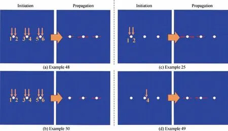
Fig. 12 Crack initiation patterns and crack growth patterns in four typical numerical examples.
4. Discussions
4.1. Main features of the proposed model
One of the main features is that the proposed model is based on peridynamic framework. In order to numerically predict fatigue behaviors,some scholars have proposed several models based on concept of fatigue element block as early as 1980s.At that time,the only powerful numerical tool is FEM,but FEM is essentially not so powerful to deal with discontinuity problems such as crack initiation, propagation and coalescence according to its underlying mathematical formulation;besides,it is also difficult to incorporate such concept of fatigue element block into FEM framework because there exist no counterparts in FEM theory to the so-called fatigue element block.As a contrast, discontinuity problems can be well handled within the peridynamic framework,and the concept of fatigue element block can also be easily incorporated into the framework by peridynamic bond. Theoretically speaking, therefore,it is more appropriate as well as convenient for a peridynamic fatigue damage-cumulative model to deal with complex fatigue problems, which has been preliminarily proven by several numerical examples in this paper. It can be seen from the above simulations that the peridynamic damage-cumulative model is capable of predicting the FCGRs,in various common structural materials as well as under different cyclic load ratios;with its probabilistic modifications, the proposed model can also give satisfying results on MSD problems.
Combined with previous works on fatigue damagecumulative models, we conclude following three indispensable points in a theoretical model of such kind:
(1) Material cyclic constitutive. It is widely acknowledged that fatigue is a plasticity-driven process, and plasticity is of great significance in fatigue crack growth under load effects as well as microstructure effects. To obtain real-time crack tip deformation fields under various loading conditions, the DIC techniques can be used in experimental measures; in numerical simulations, correspondingly, it depends on elastoplastic constitutive to achieve this goal. However, for low-stress cases an elastic constitutive may be adequate.
(2) Nonlinear crack tip parameters (NLP). Despite that parameters within linear-elastic framework may give satisfying engineering predictions in simple cases,it is commonly acknowledged that fatigue is essentially a plasticity-driven process, and a proper NLP to estimate such plasticity impacts is thus necessary. Among many NLPs, the total cyclic strain range adopted in this work is the most convenient and straightforward one.
(3) Damage-cumulative law. If the NLP answers the question of ‘‘what makes a difference”, the damagecumulative law answers ‘‘how it works”. Generally, the famed Coffin-Manson relationship or its alternate formulation will be taken as the fatigue damagecumulative law in such works, and sometimes Basquin equation is also adopted for low-stress cases. To consider cyclic ratio effects, an equivalent strain method such as Walker formulation or SWT fatigue parameter is usually incorporated.
4.2. Distinctions from the Silling model
As mentioned in Introduction, two main peridynamic models for fatigue cracking have been proposed so far. The first model,proposed by Oterkus et al.28in 2010,degrades the critical bond stretch over fatigue cycles, but the specific formulation of degradation has not been derived and to the authors’acknowledges there are no further studies into this model.The second model, proposed by Silling and Askari29in 2014,does not explicitly involve a critical bond strain for damage;instead,each bond is characterized by a history variable called the ‘‘remaining life” that accumulates over loading cycles according to the cyclic bond strain. The evolving functions of ‘‘remaining life” is derived, in which S-N curve parameters are adopted in phase I and the Paris law parameters are adopted in phase II. Some distinctions from Silling’s model will be discussed in this section.
Firstly,within the framework of linear elastic peridynamics,Silling’s model is incapable of accurately calculating the crack tip strain fields;as a remedy,for each bond within the horizon of crack tip the authors derive ‘‘fictious bond strain”from the viewpoints of linear elastic fracture mechanics, which is then adopted to degrade the‘‘remaining life”according to the Paris law.However, the derivation is based on dimensional analysis and cannot offer the specific formulation of ‘‘fictious bond strain”, which makes it a must to perform extra calibrations for the degradation parameter. Such introduction of ‘‘fictious bond strain” makes the model ‘‘does not smoothly transition between two phases”and‘‘disagrees with a measurement from a strain gauge or DIC in FCG phase”,as admitted by authors themselves.44Moreover,Silling and his co-authors extend their model to applications in nonzero load ratio and spectrum loading cases, but it is observed in experiments that such effects are to varying extents related to plasticity and thus beyond power of the model based on stress intensity factor range.As a contrast,the proposed model in this paper is based on the ‘‘real” deformation fields in both FCI phase and FCG phase. It is recommended that an elastoplastic cyclic constitutive should be adopted in the proposed model especially for large deformation fields such as areas around crack tips; nevertheless, the linear elastic constitutive can still be adopted for substitution when the stress level is limited to elastic scope for the whole deformation fields or convergence problems are met in complex multiple-crack patterns, in which calculation accuracy for cycle numbers is sacrificed but qualitative discussions are still reasonable to some extent.
Secondly, since the material constitutive is limited to linear elastic framework, Silling’s model relies on the calculation of stress intensity factor range rather than NLP to degrade bonds in FCG phase; such reliance on stress intensity factor range implies inevitable input of Paris law parameters obtained by previous experiments,which are affected by experiment conditions such as loads,microstructures and environments.On the one hand, application of the present F&DT philosophy into simulation does not reduce the workload of experiments; on the contrary, the experiment conditions in laboratory are limited but the simulation conditions are much broader. On the other hand,the predictive significance of numerical simulation is lost since experiments have been done;the results of Silling’s model are bound to be consistent with experiment data,because the fitting parameters of experiment data have been input into the model. This actually accords with the present F&DT philosophy which is based on assumed similitude between laboratory conditions and service conditions, rather than the future philosophy of digital twin. For the consideration of peridynamics features, the predictive power of peridynamics in spontaneously simulating complex crack behaviors such as deflection and branching will thus be weakened; once losing such features, there are be little advantages of peridynamics over FEM in calculation of parameters such as stress intensity factor and J-integral, no matter in accuracy or in computation efficiency. In other words, simulation methods should be established on more physical basis rather than phenomenological description; therefore, the proposed model adopts a damage-cumulative philosophy. It is worth noting again that no parameters involving the Paris law or other description model for FCGRs appear in the proposed model,but the predicted FCGRs accord well with experiment data.
To conclude, Silling’s model is essentially phenomenological, which is established on the present F&DT philosophy of assumed similitude; as a result, the physical fundamentals of fatigue problems cannot be reflected and the application to complex problems is thus limited. By contrast, the proposed peridynamic fatigue damage-cumulative model in this work attempts to simulate fatigue problems from a more physical way; capabilities of the proposed model of predicting FCGRs and MSD are preliminarily demonstrated in few examples in this paper,and its applicability to more cases should be further verified in more studies.
5. Summary
This paper proposes a peridynamic fatigue damage-cumulative model. The proposed model obtains the deformation fields based on an elastoplastic constitutive with an isotropic hardening rule using a bi-linear diagram,adopts the equivalent cyclic strain as the dominating mechanical parameter, and evolves the cumulative damage according to an alternate formulation of Coffin-Manson relationship.Bond breakage and crack propagation are characterized in the original way of peridynamics.The proposed model is verified by calculating the fatigue crack growth rates for three different kinds of alloys (2024-T3, Ti-6AL-4V and 300 M) under CA and simple VA loading cases,and the results agree well with experimental data.Then,the proposed model with probabilistic modifications is verified by simulating multiple-site-damage problems for 2024-T3 threesimilar-detail plate,in which experiment phenomena are reproduced and captured.In the end,main features of the proposed model are summarized,and distinctions from the previous models are discussed.There may be a potential for the peridynamic damage-cumulative model proposed in this work to numerically predict fatigue problems in the digital twin paradigm for future generations of aerospace vehicles.The main conclusions of this paper can be summarized as following:
(1) A fatigue damage-cumulative model within peridynamics framework is proposed,which applies to both fatigue crack initiation and fatigue crack growth.
(2) Fatigue crack growth rates under constant-amplitude and simple variable-amplitude loading cases can be predicted by the proposed model without Paris law parameters, and the simulation results accord well with experiment data.
(3) Multiple site damage problems in three-similar-detail plates can be simulated by the probabilistic extension of the proposed model,and various crack patterns observed in experiments are well reproduced and captured.
(4) Three keypoints,i.e.material cyclic constitutive,nonlinear crack tip parameters and fatigue damage-cumulative law, are indispensable in attempts to establish a macroscale physics-based model for predictions of fatigue problems.
Declaration of Competing Interest
The authors declare that they have no known competing financial interests or personal relationships that could have appeared to influence the work reported in this paper.
Acknowledgements
This study was supported by the National Natural Science Foundation of China (No. 11672012).
 CHINESE JOURNAL OF AERONAUTICS2021年2期
- CHINESE JOURNAL OF AERONAUTICS的其它文章
- Recent active thermal management technologies for the development of energy-optimized aerospace vehicles in China
- Electrochemical machining of complex components of aero-engines: Developments, trends, and technological advances
- Recent progress of residual stress measurement methods: A review
- Micromanufacturing technologies of compact heat exchangers for hypersonic precooled airbreathing propulsion: A review
- Towards intelligent design optimization: Progress and challenge of design optimization theories and technologies for plastic forming
- A combined technique of Kalman filter, artificial neural network and fuzzy logic for gas turbines and signal fault isolation
