Acceleration of unsteady vortex lattice method via dipole panel fast multipole method
Shuai DENG, Chen JIANG, Yunjie WANG, Haowen WANG
School of Aerospace Engineering, Tsinghua University, Beijing 100084, China
KEYWORDS Boundary element method;Dipole potentials;Fast multipole method;Potential flow;Unsteady vortex lattice method
Abstract The Unsteady Vortex Lattice Method (UVLM) is a medium-fidelity aerodynamic tool that has been widely used in aeroelasticity and flight dynamics simulations. The most timeconsuming step is the evaluation of the induced velocity. Supposing that the number of bound and wake lattices is N and the computational cost is O N2 ,we present an Dipole Panel Fast Multipole Method(DPFMM)for the rapid evaluation of the induced velocity in UVLM.The multipole expansion coefficients of a quadrilateral dipole panel have been derived in spherical coordinates,whose accuracy is the same as that of the Biot-Savart kernel at the same truncation degree P.Two methods (the loosening method and the shrinking method) are proposed and tested for space partitioning volumetric panels. Compared with FMM for vortex filaments (with three harmonics),DPFMM is approximately two times faster for N ∈ .The simulation time of a multirotor (N ~104) is reduced from 100 min (with unaccelerated direct solver) to 2 min (with DPFMM).
1. Introduction
The global Unmanned Aerial Vehicle (UAV)market has been rapidly growing in recent years. Vertical Take-Off and Landing (VTOL) UAVs with multiple rotors (quadcopters, hexacopters, and fixed-wing hybrid quadrotors) are widely used in civil and military applications due to their low equipment and operational costs. Aerodynamic analysis tools are needed for performance optimization, vibration and noise reduction,and flight dynamics modeling.
Computational Fluid Dynamics (CFD) is a powerful tool,but artificial viscosity leads to a higher decay rate of concentrated vorticity in rotor wake.1The high computational cost limits the application of CFD.The CFD simulation of a quadcopter took 48–72 h on a NASA supercomputer.2Such computational resources are expensive, and the time is unacceptable for designers to obtain rapid feedback.
With the assumption of potential flow, panel methods are commonly used for analyzing aircraft with medium fidelity and low computational cost. Singularities (fundamental solutions to Laplace’s equation,such as source,dipole,and vortex)are distributed on the surfaces and wakes. Boundary conditions are enforced, resulting in a set of linear algebraic equations. The strength of singularities is the solution of the equations. When neglecting the effect of thickness, lifting surfaces and wakes can be discretized into dipole panels, giving rise to the Doublet Lattice Method(DLM).3With the assumption of harmonically oscillating lifting surfaces for a prescribed flat wake, DLM is generally formulated in the frequency domain, which limits the capability of DLM to solve the nonperiodic transient response of aircraft.
Hess has proved that the velocity at an arbitrary field point by a dipole panel is identical to the velocity by a vortex ring placed at the panel’s boundary (see Appendix A of Hess’s report4). The Unsteady Vortex Lattice Method (UVLM) is developed by replacing dipole panels with vortex lattices(rings). Each vortex lattice is composed of four vortex filaments. The Biot-Savart law can compute the induced velocity of a vortex filament.UVLM is formulated in the time domain and allows arbitrary lifting surfaces under general motions with free wake distortion.Although UVLM is based on potential flow theory, viscous correction makes UVLM feasible for low Reynolds flow,5separation flow,6and compressible flow.7UVLM can be coupled with flight dynamics and structural dynamics models to build a comprehensive aeroelastic simulation model.8UVLM has been applied for multiple aircraft configurations: fixed9and flapping10wing, helicopters,11multirotor,5multi-propeller wing12and joined wing.13The computation of induced velocity in UVLM is a N-body problem: with N vortex lattices, the computation cost is of O N2.The value of N ranges from thousands to tens of thousands.As reported by Kebbie-Anthony et al.,13over 90%of the computation time is spent on evaluating the induced velocity using the Biot-Savart law.Because the induced velocity at each field point is independent of the rest, UVLM can be accelerated by parallel computing on Graphical Processing Units (GPUs).11Parallel computing is hardware dependent. There are also algorithmic approaches for efficient N-body simulation: thetreecode (such as the Barnes-Hut method14and the combined pFFT-multipole treecode15) and theFast Multipole Method (FMM). We will focus on FMM in this paper.
FMM is a divide-and-conquer algorithm that decomposes the computation domain recursively and uses multipole expansions to approximate the far-field sources. FMM has been developed to accelerate the pairwise interaction computation for Laplace’s equation,16the Gauss transform,17and the Helmholtz equation.18For evaluating the induced velocity of vortex elements, FMM for the Biot-Savart kernel can be obtained by using three independent Laplacian harmonics(for each velocity component).19Gumerov and Duraiswami20have reduced the number from three to two via the Lamb-Helmholtz decomposition. The multipole expansion of a vortex filament can be obtained by the Gauss-Legendre quadrature of vortex particles.20FMM for the Biot-Savart kernel has been implemented on both CPUs and GPUs.21–23Kebbie-Anthony et al.13,24recently integrated FMM for vortex filaments with a UVLM simulation model.
As mentioned previously, the induced velocity of a vortex ring is equal to the gradient of the velocity potential generated by an equivalent dipole panel. This equivalence leads to the idea of a Dipole Panel Fast Multipole Method (DPFMM) in this paper. There are two perspectives of a dipole panel (or a vortex lattice): when viewed from the far-field, it is a dipole panel whose contribution can be computed via the multipole approximation;when seen from the near-field,it is a vortex lattice, whose contribution can be calculated via the Biot-Savart law.Thus,only one harmonic function(the velocity potential)is needed in DPFMM.
The paper is organized as follows. We first provide a brief introduction of UVLM as the background in Section 2. The outline of FMM is described in Section 3. Two methods are proposed for space partitioning of volumetric dipole panels in Section 4. In Section 5, we present a method to obtain the spherical multipole expansions of a quadrilateral dipole panel analytically. In Section 6, we present several numerical examples to validate the proposed method, which are followed by the conclusion in Section 7.
2. Unsteady vortex lattice method
UVLM is based on solutions to Laplace’s equation.Vortex lattices (also referred to as vortex rings) are placed on the mean surface of a wing (ignoring the thickness of the wing) and the free wake. The non-penetration condition is satisfied at a number of control points. A system of linear algebraic equations is solved at each time step to determine the singularity strengths.
The mathematical derivations of well-developed theories are kept to the minimum in this section. Only necessary concepts and definitions are presented. The readers can find more details in the literature (Katz and Plotkin’s textbook25and some articles10,26–28).
2.1. Governing equation and boundary conditions
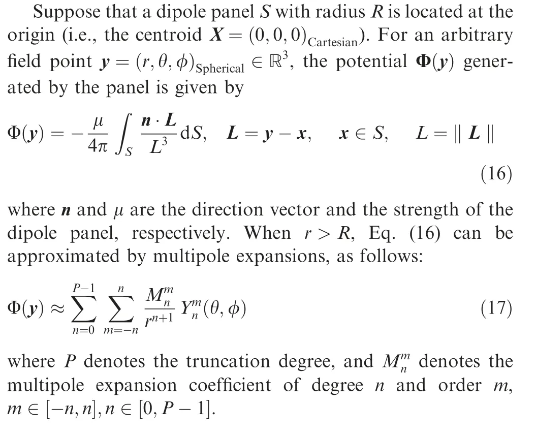
With the assumptions of potential flow,a scalar Φ called velocity potential is defined, being the gradient of the perturbation velocity v (i.e., v=∇Φ). The velocity potential Φ satisfies Laplace’s equation, as follows:

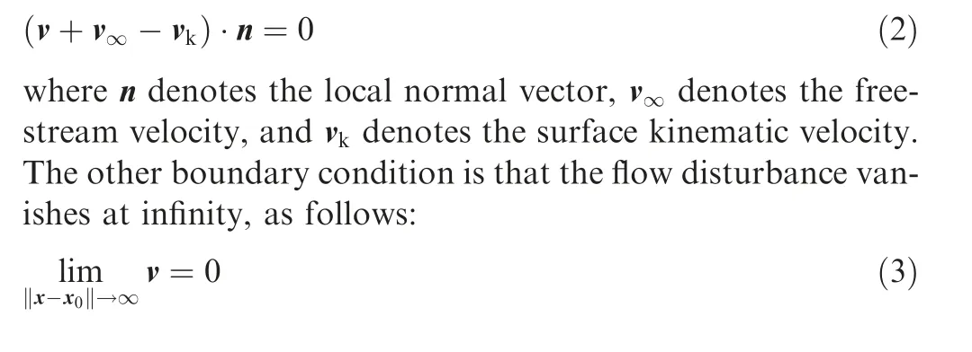
Two boundary conditions need to be specified to solve Eq.(1). The non-penetration boundary condition is enforced on the wing surface, as follows:
2.2. Formulation of UVLM
Both the velocity potential and the induced velocity obey the principle of superposition.The solution of the problem in Section 2.1 can be obtained by distributing a set of basic elementary solutions of Laplace’s equation (source, dipole, and vortex)on the boundaries.Thus Eq. (1)is automatically satisfied.Also,the influence of these elementary solutions vanishes at infinity. As a result, we only need to solve Eq. (2) with the boundary element method (BEM).
Panel methods discretize surfaces by source and dipole elements. The problem is reduced to solving the strength of the singularity elements on the boundaries. The source term is neglected in the case of thin lifting surfaces, which leads to the Dipole-Lattice Method(DLM).Hess has proved the equivalence of a constant dipole panel to a vortex ring placed at the panel’s edge.4The induced velocity of a vortex lattice with circulation strength Γ is identical to a dipole panel with the same geometry and constant dipole strength μ=Γ.
UVLM replaces the constant-strength dipole panels with equivalent vortex lattices.Vortex lattices are used to model lifting surfaces and wakes, as shown in Fig. 1.The lifting surface(the mean chamber surface) is discretized into quadrilateral wing elements. Bound vortex lattices (vortex lattices attached to lifting surfaces) are attached to these wing elements: the leading vortex line is placed at the 1/4 element chord line;the rear vortex line is placed at the 1/4 chord of the following element;the left and right lines are placed on the left and right sides of the element, respectively. The collocation point lies in the middle of the 3/4 chord line of the element (center of the vortex ring). The normal vector n is also defined at the collocation point.Wake vortex lattices are convected from the trailing edge with vorticity of the same strength to the bound vortex lattices at the trailing edge.The corner points of the free wake lattices transport with the local velocity. The nonpenetration condition Eq. (2) is enforced at all collocation points on the wing, as follows:
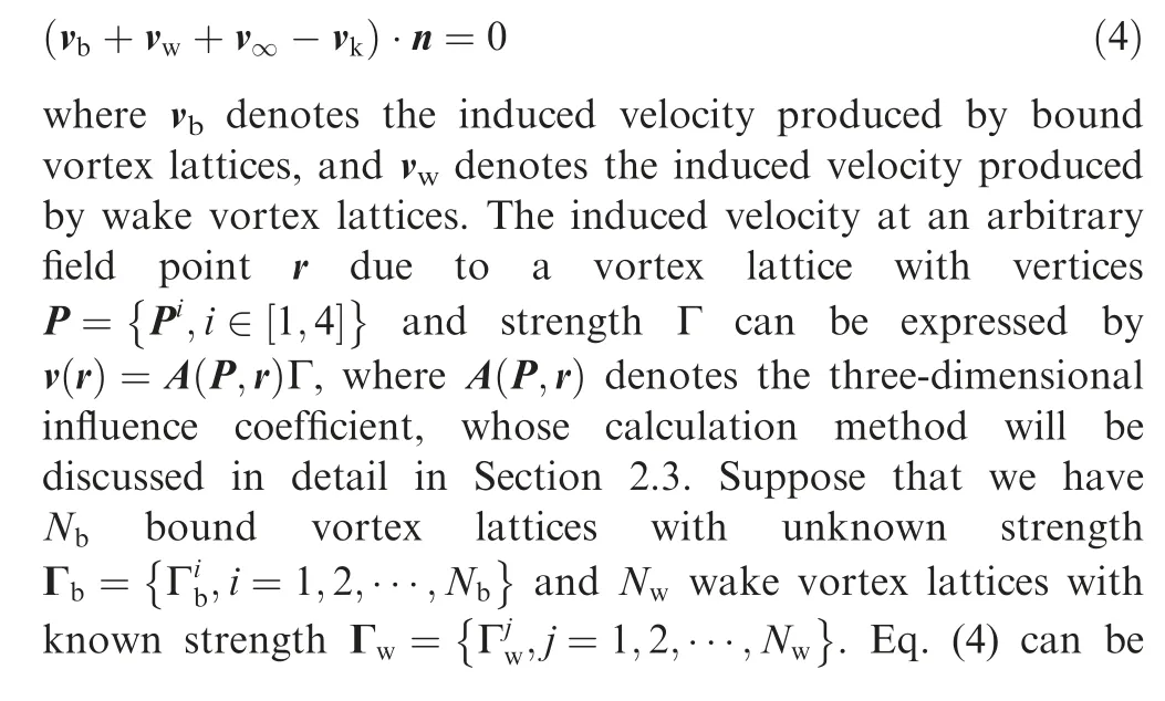
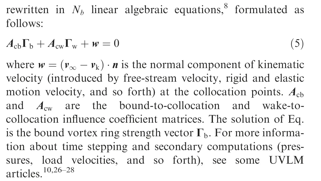
To obtain the influence matrices and the convection velocity of the wake, the induced velocity is calculated at field points (the collocation points on the wing and the corner points of the free wake). We need to compute the induced velocity at M field points produced by N vortex lattices.The induced velocity field computation is the most timeconsuming part of UVLM.
2.3. Induced velocity produced by a vortex lattice
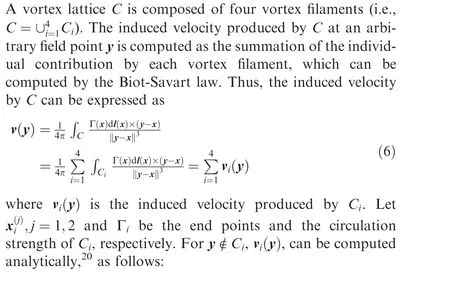
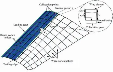
Fig. 1 Descriptive diagram of UVLM.
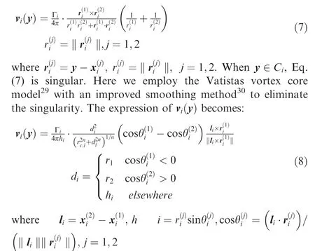
In this paper,the constant n is set to 2,and the vortex core radius rc,iis set to a small value (less than 0.5 of the smallest vortex lattice dimension in the problem under consideration,as suggested by Hirato et al.31). The induced velocity computed by Eq. (8) will quickly converge to the result obtained by Eq. (7) as the field point gets away from the neighborhood of the vortex filament.
3. Fast multipole method
The basic idea of the FMM can be expressed as
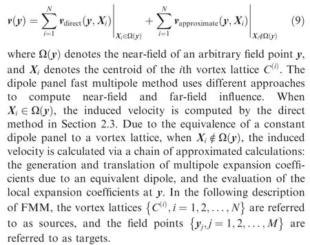
In the first stage, octrees are built to distinguish the nearand far-field. The classic octree generation algorithm (and some variations) can be found in Refs. 14,32,33. These octree algorithms are designed for particles. Only the position information of sources and targets is used in the octree generation.However, the sources (panels) are volumetric, and they may overlap multiple cells. Thus, two methods are proposed to overcome this problem in Section 4. At the end of this stage,two octrees are built for the sources and targets, respectively.Each leaf node (cell) contains several sources or targets. Each parent node (cell) contains eight child nodes at most.
After the source octree generation, the multipole expansions will be computed. The multipole expansion coefficients are first calculated in the panel-fixed frame, then translated and rotated to the cell’s center in the global frame. This stage is referred to as Panel to Multipole (P2M). We will describe P2M in detail in Section 5.
Once the multipole expansions at each leaf node have been generated, they are translated to upper-level nodes in the source octree. This stage is called Multipole to Multipole(M2M).
After the M2M stage, multipole expansions at the source octree nodes are translated to local expansions at the target octree nodes. We adopt the dual-tree traversal approach by Dehnen,34as shown in Fig.2.Cells are split according to their size until interaction can be performed.If the interacting pairs of cells are well separated, the interaction is calculated via Multipole to Local (M2L) translation. The cells are said to be well-separated if they satisfy:

where r1and r2are the radius of the source cell and the target cell,respectively;L is the distance between the cell centers;θ is the Multipole Acceptance Criteria (MAC).
After the M2L stage,local expansion coefficients are translated from upper- to lower-level nodes in the target octree.This stage is referred to as Local to Local (L2L).
For each leaf node in the target octree, the potential and induced velocity are computed at field points from the local expansion coefficients. The velocity equals the gradient of velocity potential and can be obtained via differentiation of local expansions. This stage is referred to as Local to Point(L2P). The influence of near-field lattices is computed by the direct method, which is referred to as Panel to Point (P2P).
4. Space partitioning of volumetric sources
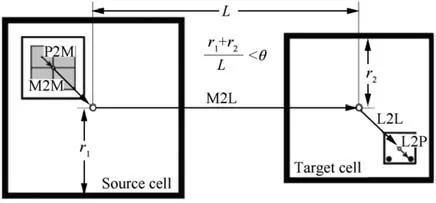
Fig. 2 Computation flow for a well-separated pair of sources and targets. The multipole coefficients are generated at the center of each leaf source cell by P2M and then translated to upper levels by M2M.If a pair of source and target cells satisfies Eq.(10),M2L is performed to calculate the local expansion coefficients at the center of the target cell. The local expansion coefficients are translated to lower levels by L2L.For each leaf target cell,an L2P operation is performed to reconstruct the potential and velocity field.
The octree data structure is widely used in FMM for hierarchical 3D space partitioning.A cubic cell(the parent node)will be subdivided into eight octants (the children nodes) recursively until the number of bodies inside the cell is less than the clustering parameter s.The classic octree addresses particles.Since the volumetric source panels may overlap multiple cells, we propose two methods to partition 3D volumetric sources.
Quadrilateral panels are the set of bodies b{ } to be partitioned. The radius R=ma‖Pi-X‖ is defined by the radius of the minimum bounding sphere of b. First, a classic octree T is constructed according to the centroids. Each node n ∈T is either a parent node(has 1–8 children nodes and contains nobodies)or a leaf node(contains bodies and has no children nodes). For a classic octree, each node n represents a cubic domain(whose center is at X and radius is R).Note that a body b may cross several cubes.We traversed the octree T in post-order,as shown in Algorithm 1.Task-based parallelism is used to accelerate the recursive algorithm.
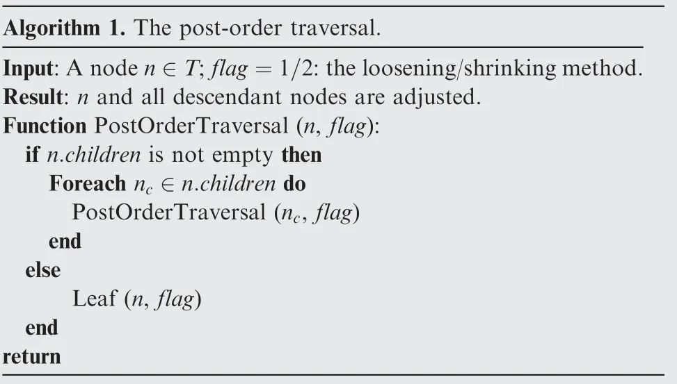
Algorithm 1. The post-order traversal.Input:A node n ∈T;flag=1/2:the loosening/shrinking method.Result: n and all descendant nodes are adjusted.Function PostOrderTraversal (n, flag):if n.children is not empty then Foreach nc ∈n.children do PostOrderTraversal (nc, flag)end else Leaf (n, flag)end return
Given the root node root, the PostOrderTraversal root,(flag) function will traverse T in post-order. Two methods are proposed to adjust node n,which are switched by flag in Algorithm 1. The first method is called the loosening method, and the second method is called the shrinking method.As shown in Fig.3,the loosening method enlarges the radii of nodes to contain all children nodes and bodies.The shrinking method finds the minimum bounding spheres of all children nodes and bodies.Thus,both the radii and the centers of nodes are adjusted.
The processing procedures for non-leaf and leaf nodes are shown in Algorithm 2 and Algorithm 3,respectively.The function Sphere(R,X)creates a sphere with center X and radius R.The queue Q is used to store spheres. The function Enqueueappends sphere S to Q. n.children denotes the set of N’s children nodes; n.bodies denotes the set of N’s bodies. The MinSphereOfSpheresfunction35,36finds the minimum bounding sphere of a queue Q of spheres.Dehnen37used a similar approach to choose the expansion centers for improved error estimation. The loosening method is easier to implement compared with the shrinking method.
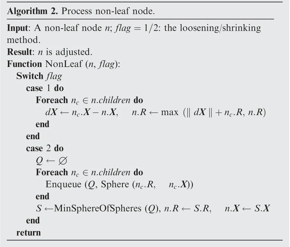
Algorithm 2. Process non-leaf node.Input: A non-leaf node n; flag=1/2: the loosening/shrinking method.Result: n is adjusted.Function NonLeaf (n, flag):Switch flag case 1 do Foreach nc ∈n.children do dX ←nc.X-n.X, n.R ←max ‖dX‖+nc.R, n.R)(end end case 2 do Q ←∅Foreach nc ∈n.children do Enqueue (Q, Sphere (nc.R, nc.X))end S ←MinSphereOfSpheres (Q), n.R ←S.R, n.X ←S.X end return
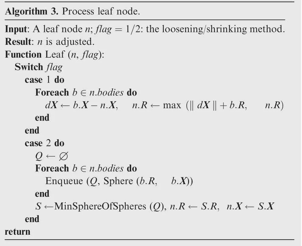
Algorithm 3. Process leaf node.Input:A leaf node n;flag=1/2:the loosening/shrinking method.Result: n is adjusted.Function Leaf (n, flag):Switch flag case 1 do Foreach b ∈n.bodies do dX ←b.X-n.X, n.R ←max ‖dX‖+b.R, n.R)(end end case 2 do Q ←∅Foreach b ∈n.bodies do Enqueue (Q, Sphere (b.R, b.X))end S ←MinSphereOfSpheres (Q), n.R ←S.R, n.X ←S.X end return
Recall the multipole acceptance criteria Eq.(10),and r1and r2by the shrinking method are always smaller (at least equal)compared with those by the loosening method. This property is beneficial for error bounding.The loosening method tends to overestimate the error, thus allowing fewer M2L operations compared with the shrinking method.
5. Panel to multipole
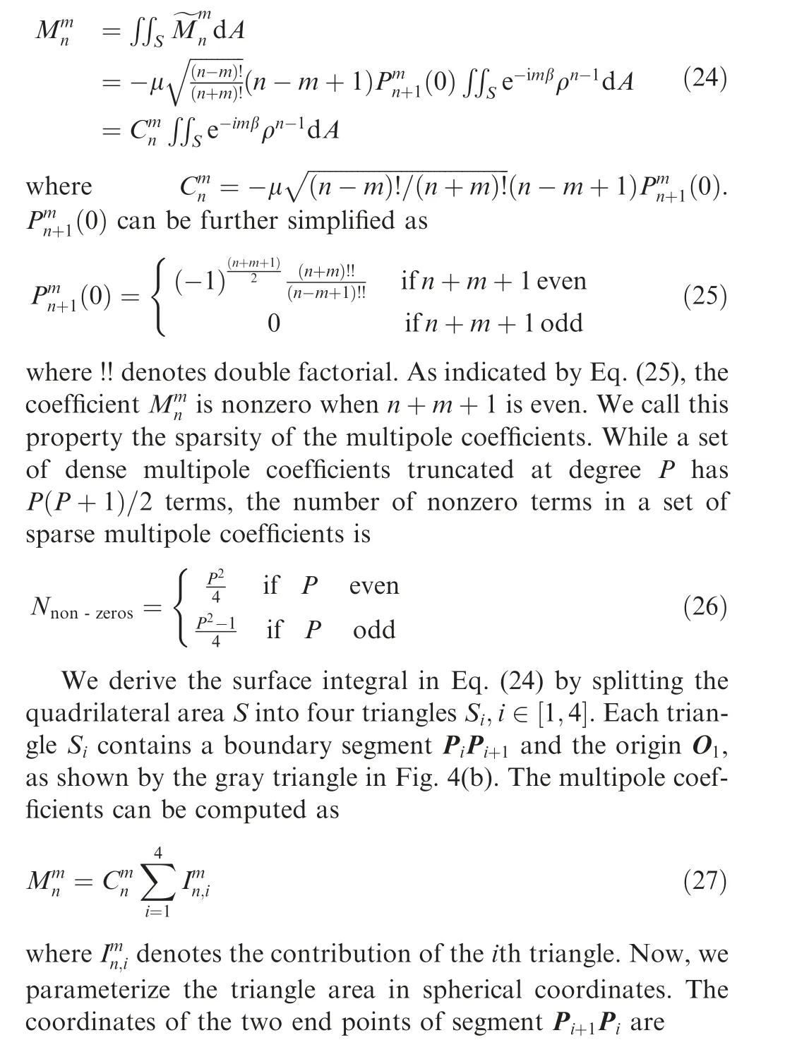
In this section,we present the multipole expansion coefficients of a quadrilateral dipole panel. The dipole density is assumed to be constant over the panel.Newman38derived the multipole expansions for both monopole and dipole quadrilateral panels.Newman’s multipole expansions are in the Cartesian coordinate, which are difficult to use in spherical-harmonics-based FMM frameworks. Gorn and Berkov39have derived the analytical multipole coefficients of a point dipole in spherical coordinates.We need to integrate the point dipole coefficients over the panel. Direct integration in 3D is difficult due to its complexity. We convert the quadrilateral panel to a panel-fixed local coordinate system. Although the problem has been converted to 2D,there are still some techniques that are needed to obtain the analytical indefinite integrals. The resulting multipole coefficients of a dipole panel are then shifted to the center of the leaf cell and rotated to coincide with the global frame.
5.1. Mathematical preliminaries
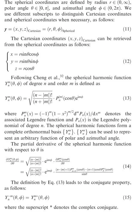
5.2. Coordinate systems
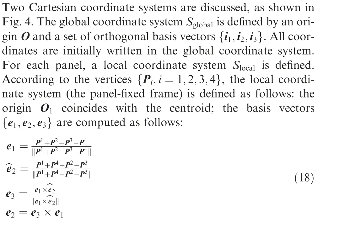
The coordinates of the vertices are converted to the local coordinate system before computation in Section 5.3.
5.3. Multipole expansions of a quadrilateral dipole panel
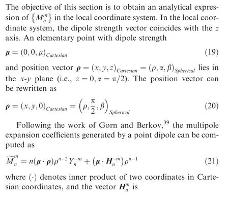
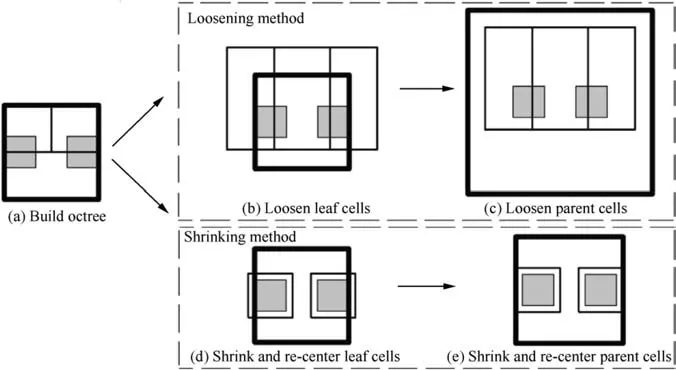
Fig.3 Space partitioning procedure by the loosening method((a)→(b)→(c))and the shrinking method((a)→(d)→(e)).Two gray lattices represent the source panels. The demo octree only has two levels: the box with the thicker border is the parent cell, and the boxes with thinner borders are leaf cells.

With Eq. (14), (19), (20) and (22), simplifications can be applied to Eq. (21), as follows:
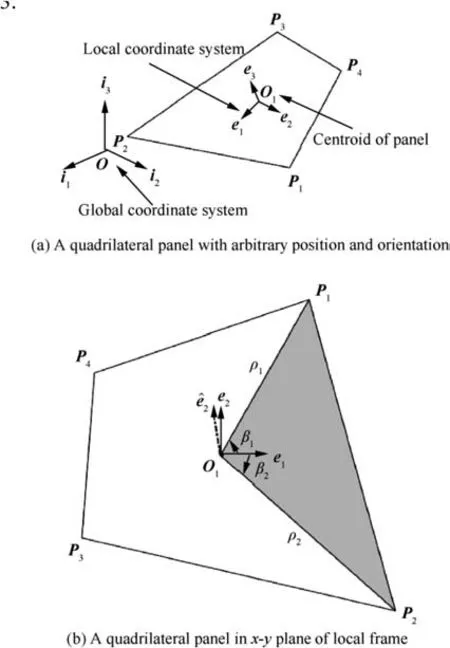
Fig.4 A local coordinate system is defined for each panel for the calculation of multipole expansion coefficients and the quadrilateral panel is divided into four triangles. The gray region indicates the area of the double integral for one triangle. The limits of the integral include one edge P1P2 and two lines connecting the centroid and two vertices O1P1 and O1P2.
Due to the conjugate property Eq. (15), only m ≥0 terms need to be computed.Thus,m ≥0 is assumed in the following derivation. With simplification in Eq. (23), the multipole coefficient equals the integral of Eq. (21) over the panel’s area S:
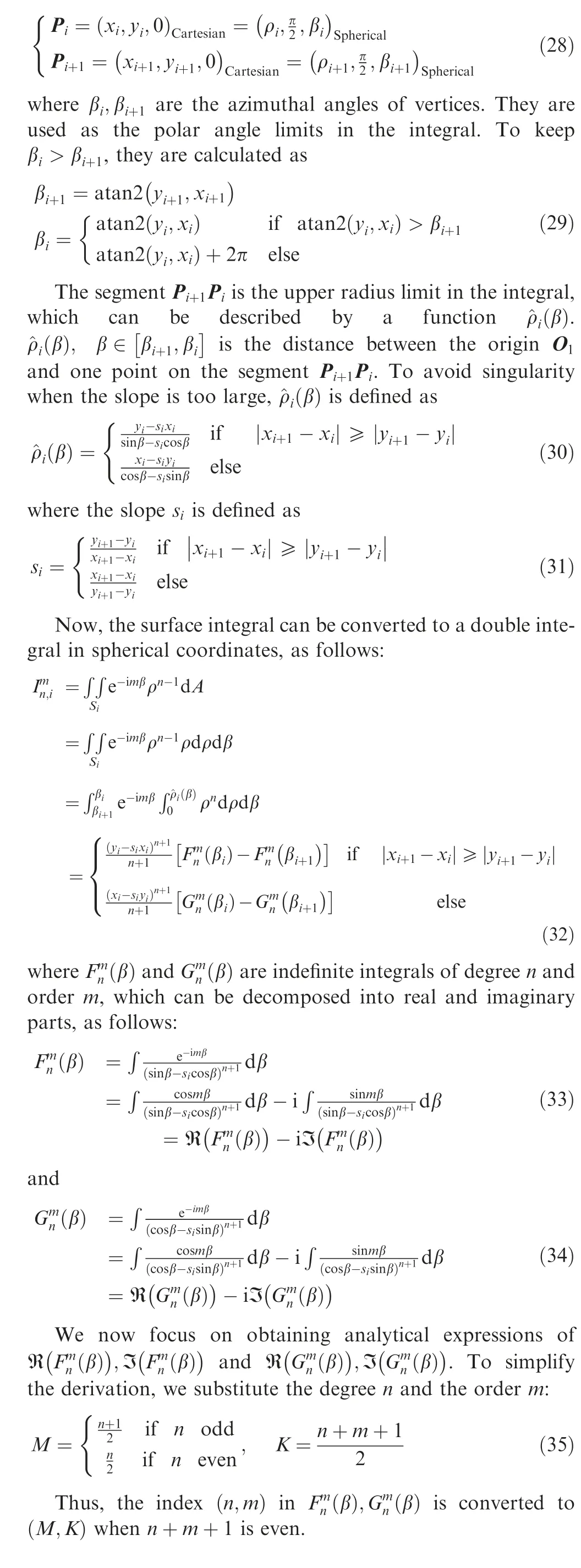
We expand the cosine function by Chebyshev polynomials of the first kind, and we expand the sine function by Chebyshev polynomials of the second kind in the numerators of Eq.(33). The substitution u=tanβ is made. Then, we use partial fraction expansion (PFE) to expand the rational functions.
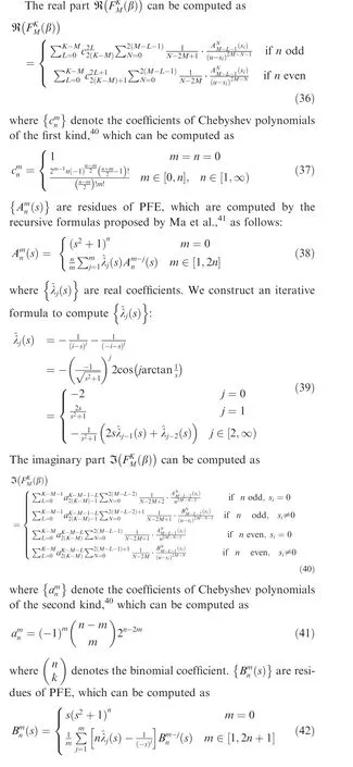
We expand the cosine function by Chebyshev polynomials of the first kind, and we expand the sine function by Chebyshev polynomials of the second kind in the numerators of Eq.(34). The substitution u=cotβ is made. Then, we use PFE to expand the rational functions.
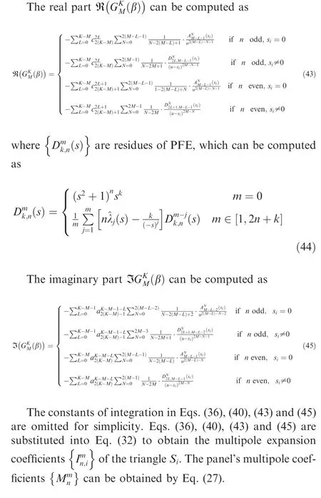
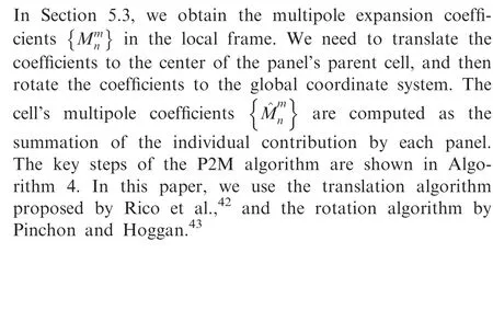
5.4. The P2M algorithm
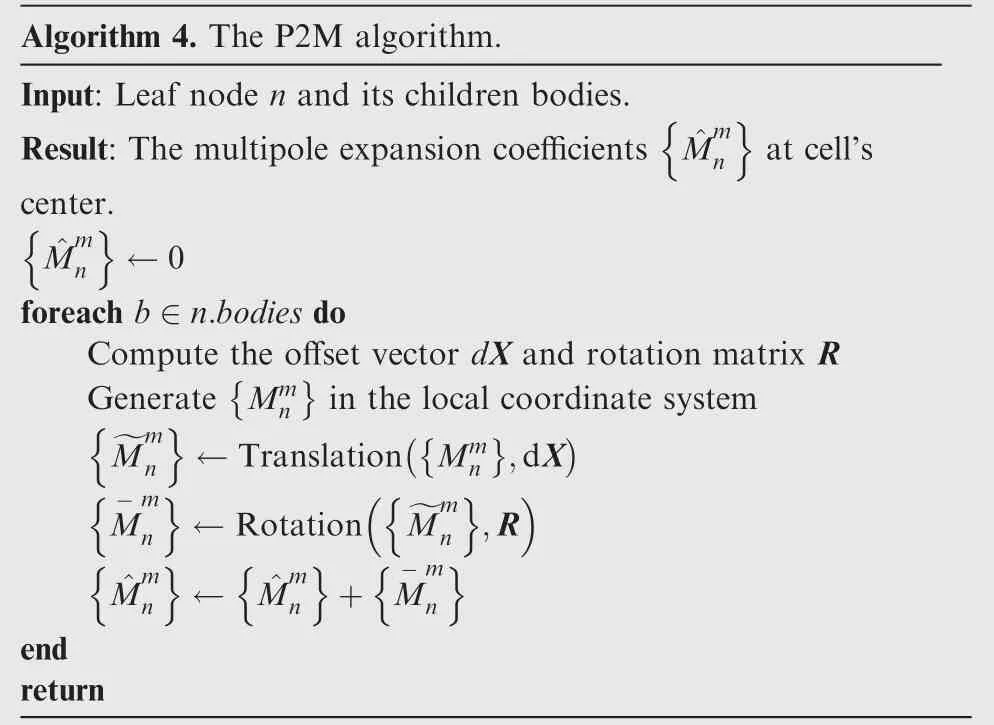
Algorithm 4. The P2M algorithm.Input: Leaf node n and its children bodies.Result: The multipole expansion coefficients ^Mm at cell’s center.^Mm n ←0 foreach b ∈n.bodies do Compute the offset vector dX and rotation matrix R Generate Mmn n in the local coordinate system~Mm n ,dX ←Translation Mmn M- mn ←Rotation ~Mm n ,R^Mmn ← ^Mm n + M-m n end return
6. Numeric examples
The algorithms in this paper were implemented in C++.The UVLM framework was developed based on the algorithms in Katz’s textbook.25The implementation of FMM was based on the state-of-the-art open-source code ExaFMM.44All experiments were run on a desktop computer with an Intel® CoreTMi7-8700 CPU(3.20 GHz)and 16 GB RAM.The code was compiled using Microsoft® Visual C++ compiler. Parallel computation with 6 CPU cores was used to obtain the performance data unless otherwise stated.
We also implemented FMM for vortex filaments for numeric comparison.The induced velocity produced by a vortex filament can be expressed in terms of three dependent scalar harmonic functions or two independent scalar harmonic functions by using the Lamb–Helmholtz decomposition.20In this paper, the three harmonics version was implemented for the following reasons. First, the three harmonics version is simpler for implementation.The Lamb–Helmholtz decomposition of the velocity in terms of two scalar potentials is not invariant with respect to translation. Special translation operators are required. Second, as reported by Kebbie-Anthony et al.,13the overall performance (in terms of speed versus error) for the two and three harmonics versions is about the same. The two harmonics version was found to be about 20% faster while producing larger errors. Thus, the comparison between the presented method and FMM for vortex filaments with three harmonics should be fair.
6.1. P2M tests
6.1.1. Accuracy of multipole expansion coefficients
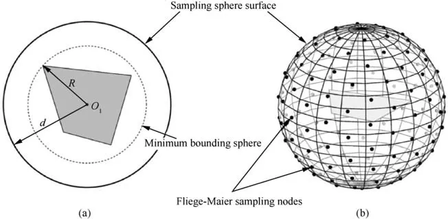
Fig.5 Illustration of multipole expansion coefficients test.(a)A panel centered at the origin lies in the x-y plane,with random shape and constant doublet strength.The inner sphere with radius of R is the minimum bounding sphere of the panel.The outer sphere with radius of d is the sampling sphere surface. (b) The Fliege-Maier sampling nodes were used as field points. They were placed on the sphere surface with radius of d.
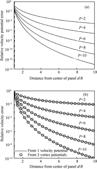
Fig. 6 Mean relative error of potential and velocity. (a) Mean relative error of the potential by multipole expansion coefficients against analytic method. The expansion order was varied from 2 to 10.(b)Mean relative error of the velocity.The solid lines denote the velocity reconstructed from the multipole expansion coefficients derived in Section 5.3. The circles denote the velocity reconstructed from three vortex potential multipole expansion coefficients.
To validate the multipole expansion coefficients derived in Section 5.3,we conducted a numeric test to compare the potential and velocity recovered from the coefficients.We first generated a square panel in the x-y plane with side length a, and then added random shape disturbance δx ∈0,0.5a[ ],δy ∈0,0.5a[ ]to each vertex.The panel was shifted to keep the centroid coinciding with the origin. The multipole expansion coefficients were computed by the method in Section 5.3. The field points were distributed on the surface of a sphere with radius of d ∈[R , 10R], as shown in Fig. 5, where R is the radius of the panel.
The relative error of the potential is defined as
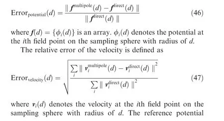
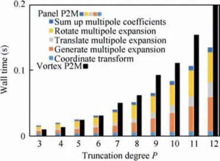
Fig.7 P2M performance of panel P2M(shown as colored bars)and vortex filament P2M(shown as black bars).The wall time was measured with one CPU core.
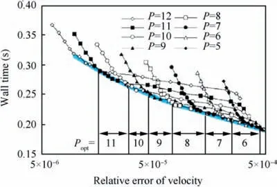
Fig. 8 Optimal cost-accuracy line on the cost-accuracy graph.N=104 vortex lattices were randomly distributed inside a cube.The clustering parameter s=60. We performed θ sweeps for P ∈5,12[ ]. Each black curve corresponds to a θ sweep while keeping P constant. The blue curve denotes the optimal costaccuracy line. In a specific relative error interval, there is an optimal truncation degree Popt, which minimizes the calculation time. The wall time is the mean value of 30 tests.

The mean relative error of 100 tests is shown in Fig. 6. To avoid crowded plots, only the results for P=2,4,6,8,10 are plotted. We also computed the relative error of the velocity reconstructed from the multipole expansion coefficients of vortex filaments (by using Gauss quadrature20) with three scalar harmonics, shown as circles in Fig. 6(b). Both the potential error and velocity error are decreasing functions of d/R. The errors will decay faster for a higher truncation degree P, as expected. As shown in Fig. 6(b), the velocity reconstructed from one scalar potential and three vortex potentials have the same accuracy level at the same truncation degree P.
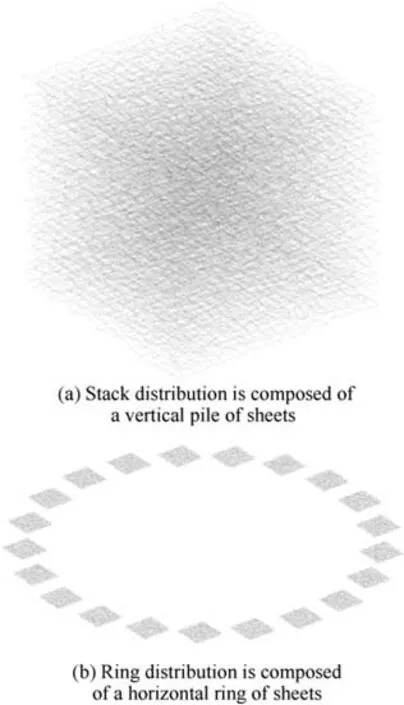
Fig. 9 Two distribution patterns. Both distributions had 21 vortex sheets.Each vortex sheet had 22 rows and 22 columns.The number of bodies N=10164. Random shape disturbances were added to each lattice in the x-y plane.
6.1.2. Performance test
We conducted a performance test of Algorithm 4. The results were compared with vortex filaments P2M(with three harmonics). A vortex sheet composed of N=104vortex lattices was used.
The results are shown in Fig.7.A crossover point at P=6 can be observed.When P<6,the wall time of the panel P2M is greater compared with the vortex P2M. When P>6, the panel P2M becomes more efficient. When P is large, the cost of P2M is dominated by the generation, translation, and rotation of multipole coefficients. The complexity of the panel P2M algorithm with respect to the truncation degree P is O P3.
6.2. FMM tests
6.2.1. Comparison of space partitioning methods
Two methods were proposed in Section 4 to address volumetric sources. We conducted this test to compare their performance.
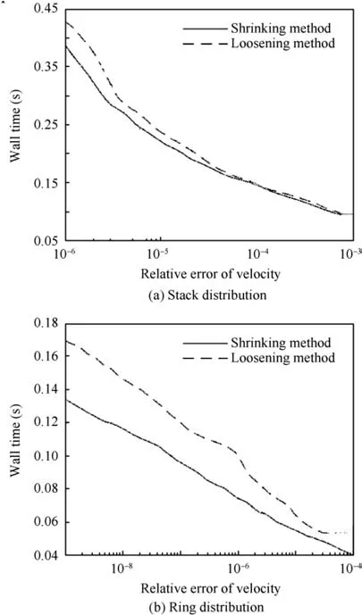
Fig.10 Optimal cost-accuracy lines of the shrinking method and the loosening method.
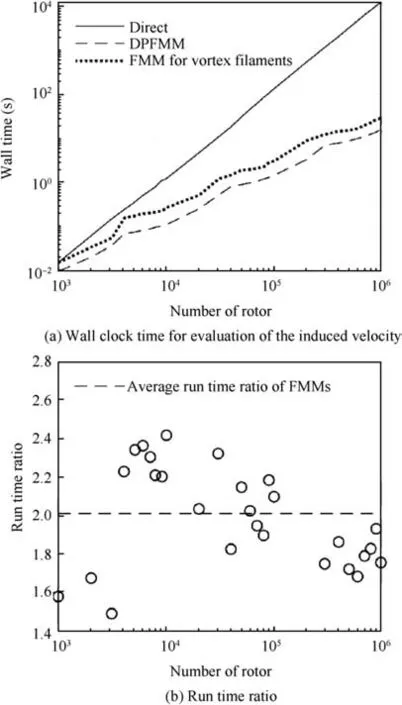
Fig. 11 Performance test.
The truncation degree P and MAC θ have a significant influence on the accuracy and computation time of FMM. A higher P will improve the accuracy of FMM,with longer computation time.A lower θ will allow more P2P computation and less M2L computation, thereby enhancing accuracy while increasing the computation time. To conduct a fair test between the two methods, we define an optimal costaccuracy line,as denoted by the blue line in Fig.8.The optimal cost-accuracy line is defined by connecting the minimal computation time needed by a specified accuracy on the costaccuracy graph. The optimal cost-accuracy line indicates the best combination of P and θ at certain accuracy.
DPFMM adopts one scalar harmonic function, while FMM for vortex filaments adopts three scalar harmonic functions. Most computation stages in FMM (P2M, M2M, M2L,L2L, L2P, as described in Section 3) will benefit from fewer numbers of harmonics functions, as almost 2/3 computation task is reduced. The total acceleration ratio 2 is smaller than 3, because the P2P computation workload remains the same.
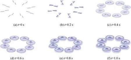
Fig. 12 Wake geometry of a multirotor undergoing a rotational speed ramp, simulated by UVLM accelerated by DPFMM. Black meshes denote blade bound lattices; blue meshes denote wake lattices.
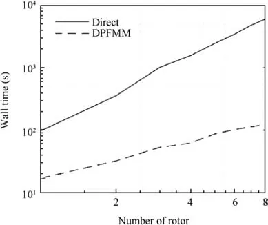
Fig. 13 Wall clock time for UVLM simulation.
6.2.3. Time-stepping test
We tested the time-stepping UVLM accelerated by DPFMM(P=10,θ=0.9,s=60, the shrinking method). The explicit Runge-Kutta fourth-order method was used for time integration,which indicates that the induced velocity needs to be evaluated four times for each time step. The integration step size was 0.001 s.A multirotor aircraft was under a rotational speed ramp for 1 s,as shown in Fig.12.The number of rotors(1400 vortex lattices per rotor) was varied from 1 to 8. The UVLM simulation wall time is shown in Fig. 13. As the number of rotors increases, the reduction of computational efforts became significant. For eight rotors, the UVLM with direct Biot-Savart evaluation consumed 100.3 min. The time was reduced to 2.1 min by DPFMM with a relative velocity error on the order of 10-5.
7. Conclusions
(1) A Dipole Panel Fast Multipole Method (DPFMM) is developed to accelerate the induced velocity computation in the Unsteady Vortex Lattice Method (UVLM).The velocity field by a constant-strength quadrilateral dipole panel (whose induce velocity equals a vortex lattice)can be expressed in terms of one independent scalar harmonic function.
(2) The multipole expansion coefficients (in spherical coordinates) of a quadrilateral dipole panel have been derived analytically.The accuracy of the velocity potential kernel is the same as that of the vortex potential kernel for the same truncation degree P.
(3) Two methods have been proposed to address volumetric source panels. We show the advantage of the shrinking method over the loosening method, especially when the sources are highly clustered.
(4) The average run time ratio(between FMM for vortex filaments and DPFMM) is approximately 2.
 CHINESE JOURNAL OF AERONAUTICS2021年2期
- CHINESE JOURNAL OF AERONAUTICS的其它文章
- Recent active thermal management technologies for the development of energy-optimized aerospace vehicles in China
- Electrochemical machining of complex components of aero-engines: Developments, trends, and technological advances
- Recent progress of residual stress measurement methods: A review
- Micromanufacturing technologies of compact heat exchangers for hypersonic precooled airbreathing propulsion: A review
- Towards intelligent design optimization: Progress and challenge of design optimization theories and technologies for plastic forming
- A combined technique of Kalman filter, artificial neural network and fuzzy logic for gas turbines and signal fault isolation
