A compliant polymorphing wing for small UAVs
Sdique P. MUHAMMED, Rfic M. AJAJ, Kmrn A. KHAN
a Department of Mechanical Engineering, United Arab Emirates University, Al Ain 15551, United Arab Emirates
b Department of Aerospace Engineering, Khalifa University of Science and Technology, Abu Dhabi 1277 88 , United Arab Emirates
KEYWORDS Camber morphing;Chord morphing;Compliant structures;Flexible skin;UAVs
Abstract This paper presents the development of a novel compliant polymorphing wing capable of chord and camber morphing for small UAVs. The morphing wing can achieve up to 10% chord extension and±20°camber changes. The design, modeling, sizing, manufacturing and mechanical testing of the wing are detailed.The polymorphing wing consists of one continuous front spar fixed to the fuselage and a rear spar on each side of the wing. Each rear spar can translate in the chordwise direction(chord morphing)and rotate around itself(camber morphing).A flexible elastomeric latex sheet is used as the skin to cover the wing and maintain its aerodynamic shape whilst allowing morphing.The loads from the skin are transferred to the spars using the compliant cellular ribs that support the flexible skin and facilitate morphing. Pre-tensioning is applied to the skin to minimize wrinkling when subject to aerodynamic and actuation loads. A rack and pinion actuation system,powered by stepper motors, is used for morphing. Aero-structural design, analysis and sizing are conducted. Performance comparison between the polymorphing wing and the baseline wing(non-morphing) shows that chord morphing improves aerodynamic efficiency at low angles of attack while camber morphing improves efficiency at high angles of attack.
1. Introduction
In the context of aviation,morphing is defined as a set of technologies adopted to improve the performance of a vehicle by changing certain characteristics to adapt to the changing mission environment during its operation.1The idea of morphing is not new.In fact,morphing technologies have appeared since the earliest days of the heavier-than-air aviation based on the observation of the ability of birds that can change the wing shape during the flight.2Barbarino3presented an extensive review of morphing aircraft technologies and their applications.Similarly,Li4reviewed methods and tools used for modeling and analyzing morphing wings. Since the focus of this paper is on chord and camber morphing, only relevant literature is discussed.
Bakshaev LIG-7, designed in USSR in 1937, was the first aircraft capable of chord morphing.1The design consisted of six chordwise overlapping wing sections where a telescopic mechanism was used to retract and extend the chord manually using tensioned steel wires from the cockpit. Recently, Sahin and Yaman5used a novel scissor structural mechanism for active chord and camber morphing. The mechanism consists of a four-bar linkage and various Scissor-Like Elements(SLEs).The scissor-structural mechanism has different camber lines with a minimum structural error which helps to achieve the desired airfoil shapes. Changing the properties and types of SLEs used can enable the changes in the chord length. On the other hand, Krishnamurthi and Gandhi6developed a simulation model of the UH-60 Black Hawk rotor to investigate the effect of on-blade extendable tab mechanism, a chord extension morphing mechanism for rotor track and balance which uses an extendable trailing edge plate over a spanwise section of each blade. A weighted least-squares optimization method was used to study the effect of the extendable tabs on controlling vibration loads. Woods and Friswell7introduced the Fishbone Active Camber (FishBAC) which enables a large, continuous changes in airfoil camber. A thin bending beam spine with stringers is running in chord wise direction of the airfoil. The stringers are branching off to a pre-tensioned Elastomeric Matrix Composite(EMC)skin surface.The front spar of the airfoil is a D spar in which the actuators are accommodated.The actuators are used to morph the trailing edge of the airfoil through an antagonistic pair of tendons. Further investigations and developments including optimization and aerodynamic modeling has been carried on FishBAC concept by Woods and other researchers.8-16Kumar et al.17conducted a comparative study of structural and aerodynamic analysis between FishBAC concept and variable camber morphing wing with single corrugated structure. The results show that the variable camber morphing configuration with double corrugated structure can take more load without severe deformation resulting in higher aerodynamic efficiency compared with the other configurations. Alsaidi et al.18modeled and conducted stress/strain analysis for a skin structure used for Variable Camber Compliant Wing(VCCW).They investigated the performance of the skin when subjected to aerodynamic load during camber morphing. A NACA2410 airfoil was able to morph to a NACA8410 with a total of 6%changes in camber.Similarly, Yokozeki et al.19developed a camber morphing wing using corrugated structures. The corrugated structures were used at the trailing edge region of the wing which deploys using a wire connected to an actuator mounted inside the wing.The morphing deformation and actuation force was estimated using nonlinear finite element analysis. Moreover, the aerodynamic performance of the developed wing was compared with the conventional hinged wing using wind tunnel.Results from the wind tunnel tests show that the morphing wing was superior to the conventional wing with hinged control surfaces.Sahin et al.20conducted aerodynamic modeling and analysis of a morphing airfoil actuated using four-bar linkages and scissor like mechanism.The mechanism consists of several scissorlike elements located at the trailing edge of the airfoil to morph into desired shapes. The aerodynamic analysis has been performed using Reynolds Transport Theorem at incompressible flow conditions as the maximum speed range of the sample aircraft is below Mach number 0.3. Arena et al.21designed and manufactured a camber morphing aileron which allowed controlling the lift distribution along the wingspan using electromechanical actuators. The mechanism consisted of unshafted servo-electromechanical actuation connected to ribs by means of double-sided guides and fork-shaped crank. The performance of the actuators is modeled numerically and validated with the actuation of the prototype manufactured.Moreover, wind tunnel tests were carried out to investigate the aerodynamic performance. Piquee et al.22analyzed a camber morphing flexible membrane wing at three Reynolds numbers using URANS TAU-Code and FEM CARAT++solver. The wing consisted of an elasto-flexible membrane sewed onto the rigid leading edge and trailing edge spars.The study was complemented by wind-tunnel testing to verify the accuracy of the computational results. Li23introduced a chordwise continuous variable camber technology based Morphing Drag Rudder(MDR).The last quarter of a NACA0012 airfoil was morphed and is divided into two control surfaces having the ability to deflect symmetrically. The morphing section is actuated using a high stiffness tendon connected to a winch for a smooth and continuous bending deflections. The high-fidelity aerodynamic analysis of MDR was carried out to compare it with the Traditional Drag Rudder (TDR). The results showed that the MDR generates higher drag at small angles of attack. The structural deformation analysis showed that the deformation caused by the aerodynamic load increases slowly with the angle of deflection. Abdessemed et al.24conducted a numerical study to investigate the aerodynamic performance of harmonically oscillating morphing Trailing Edge Flap (TEF) at Re=0.62×10⁶and 4° angle of attack. The study focused on the effect of changing the frequency and amplitude of the oscillating TEF on the aerodynamic efficiency and the flow structure using dynamic meshing. The study showed that at constant amplitudes and specific high frequencies, there is a slight increase in the aerodynamic efficiency when compared with the baseline design. On the other hand,at constant frequencies for a range of amplitudes, up to 3%of an increase in the aerodynamic efficiency can be achieved.
This paper develops a compliant polymorphing wing capable of chord and camber morphing suitable for small UAVs.The design consists of a fixed leading edge spar and a rear spar capable of chordwise translational motion for chord morphing and rotational motion for camber morphing. A rack and pinion actuation mechanism driven by a stepper motor is used to facilitate the rear spar translation while two stepper motors facilitate the spar’s rotation. The actuation system is housed in the wing-fuselage junction.A latex elastomeric sheet is used as the skin to maintain the aerodynamic shape while allowing morphing.The skin is supported by compliant ribs with cellular structure. Structural analysis and sensitivity studies are conducted using Femap with NX Nastran.Moreover,XFOIL panel method is used for aerodynamic prediction and for comparing the performance of the morphing wing with that of the baseline wing equipped with hinged flaps.
2. The polymorphing wing
2.1. UAV
A small RC airplane with a rectangular, untapered, unswept wing is used as the basis of this study. The wing has a chord of 0.25 m, a span of 1.3 m, and cruising speed of around 20 m/s. The airfoil is NACA0012 and the maximum takeoff weight of the UAV is around 5 kg.
2.2. Morphing concept
The polymorphing wing developed here is capable of up to 10% increase in the chord and ±20° camber variations. Two separate actuation mechanisms are used to achieve chord and camber morphing independently. Chord morphing is achieved using a rack and pinion mechanism,where the rear spars of the wing are attached to the rack and translate rearward relative to the fuselage while having the front spar fixed to the fuselage.Fig. 1 shows the CAD model of the morphing wing and the actuation mechanism.
Fig. 2 shows the schematic of the morphing concept. The rack and pinion system is driven by a stepper motor facilitating symmetric chord morphing. On the other hand, camber morphing is achieved by rotating each rear spar around itself.Two stepper motors are used to facilitate symmetric and asymmetric camber morphing.The actuation systems for both morphing degrees of freedom are housed in the fuselage to reduce complexity and maximize synergy. The morphing wing consists of a hollow spar with a square cross-section positioned at 10% chord and a circular rear spar of 6 mm diameter positioned at 77.5% chord. The front spar is fixed/clamped to the fuselage ribs/bulkheads for optimal load transfer. The front and rear spars are connected using a number of compliant ribs and rails. The compliant ribs support the flexible elastomeric skin whilst allowing morphing and the rails ensure the smooth transfer of loads between the two spars providing an appropriate level of structural integrity.
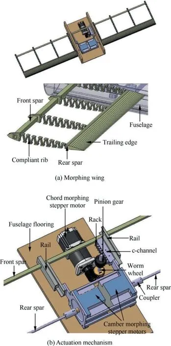
Fig. 1 A CAD model of polymorphing wing.
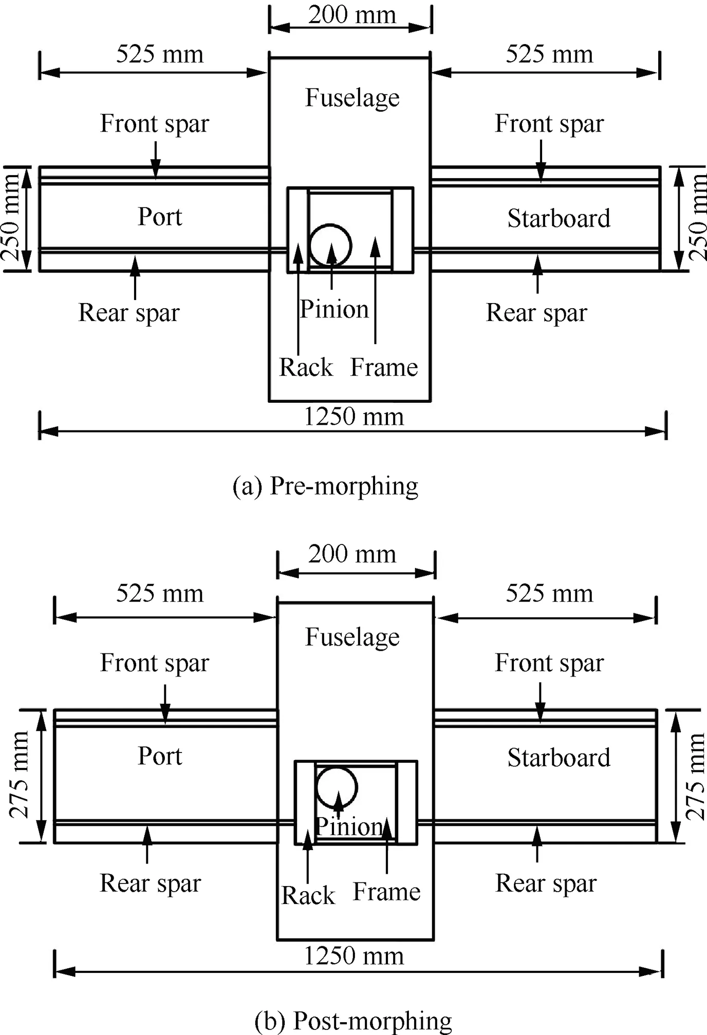
Fig. 2 Schematic of morphing concept.
The compliant rib consists of a D-section running from leading edge to 15%chord and a zigzag cellular structure running from 15 % to 75% chord as shown in Fig. 3. Fig. 3(a)shows the schematic of the compliant rib and Fig. 3(b) shows the 3D printed compliant rib.The zigzag cellular structure for the compliant rib was used to minimize the actuation power/-force requirement for morphing.
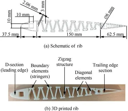
Fig. 3 Zigzag compliant rib.
2.3. Structural components and sizing
The compliant ribs are made of cellular structures to facilitate morphing.Two cellular structural configurations were studied:zigzag and diamond as shown in Fig. 4. A structural analysis was carried out to evaluate the properties of each configuration using Femap with NX Nastran. This analysis was carried out to investigate which cellular structure is more suitable for chord morphing. A single cell of each structural configuration is considered. A Young’s modulus of 1.94 GPa and Poisson’s ratio of 0.35 were considered during analysis assuming that the cells are made of ABS plastic. The walls of each cell are modeled as rectangular beam elements(CBEAM)whose depth is 10 mm.Femap with NX Nastran uses the Timoshenko beam model.The cells have the same width and length and are made of beams of similar thickness.Each cell is clamped at one side and a unit axial force(1 N)is applied on its other end as shown in Fig.4.The zigzag cell undergoes large translation and rotation(due to asymmetry)when subject to axial loads.The analysis performed here is linear structural analysis due to the small deformations of the walls.To simulate the actual profile of loading,an additional constraint is applied to the zigzag cell to eliminate global rotation and to allow only for translation.The additional constraint is applied to replicate the real scenario where the rotation Degree of Freedom (DOF) of the structure is restricted by the front spar and rear spar.The axial force is applied uniformly using artificial rigid elements as shown in Fig. 4.
It is evident that the zigzag configuration is more flexible allowing larger deformations. To determine the sensitivity of stiffness of each cell configuration to beam thickness,the thickness is varied gradually from 1 mm to 2.1 mm with a step of 0.1 mm, then a unit axial force is applied. Fig. 5 shows the variation of axial stiffness of each cell with the thickness of the wall beams. It can be seen that the diamond configuration is way stiffer than the zigzag, making the zigzag configuration more promising for chord morphing due to the low actuation force needed. This can be clearly seen from Fig. 5 where the stiffness of the diamond configuration is much higher than that of the zigzag. For instance, at a wall thickness of 1.3 mm, the stiffness of the diamond cell is 10 times the stiffness of the zigzag cell.Similarly,at 2.1 mm,the stiffness of the diamond is 10 times that of the zigzag. For morphing wing application, it is desirable to have the flexibility in the direction of morphing and rigidity in the out-of-plane direction to support the skin and withstand the aerodynamic loads. When comparing the zigzag and diamond cells, it appears that the zigzag is flexible in both the morphing direction and the out-of-plane direction.However, the structure philosophy adopted here utilizes two rigid spar at the leading and trailing edge to provide the required bending rigidity. Therefore, the zigzag cellular structure is chosen to minimize the actuation force/moment.
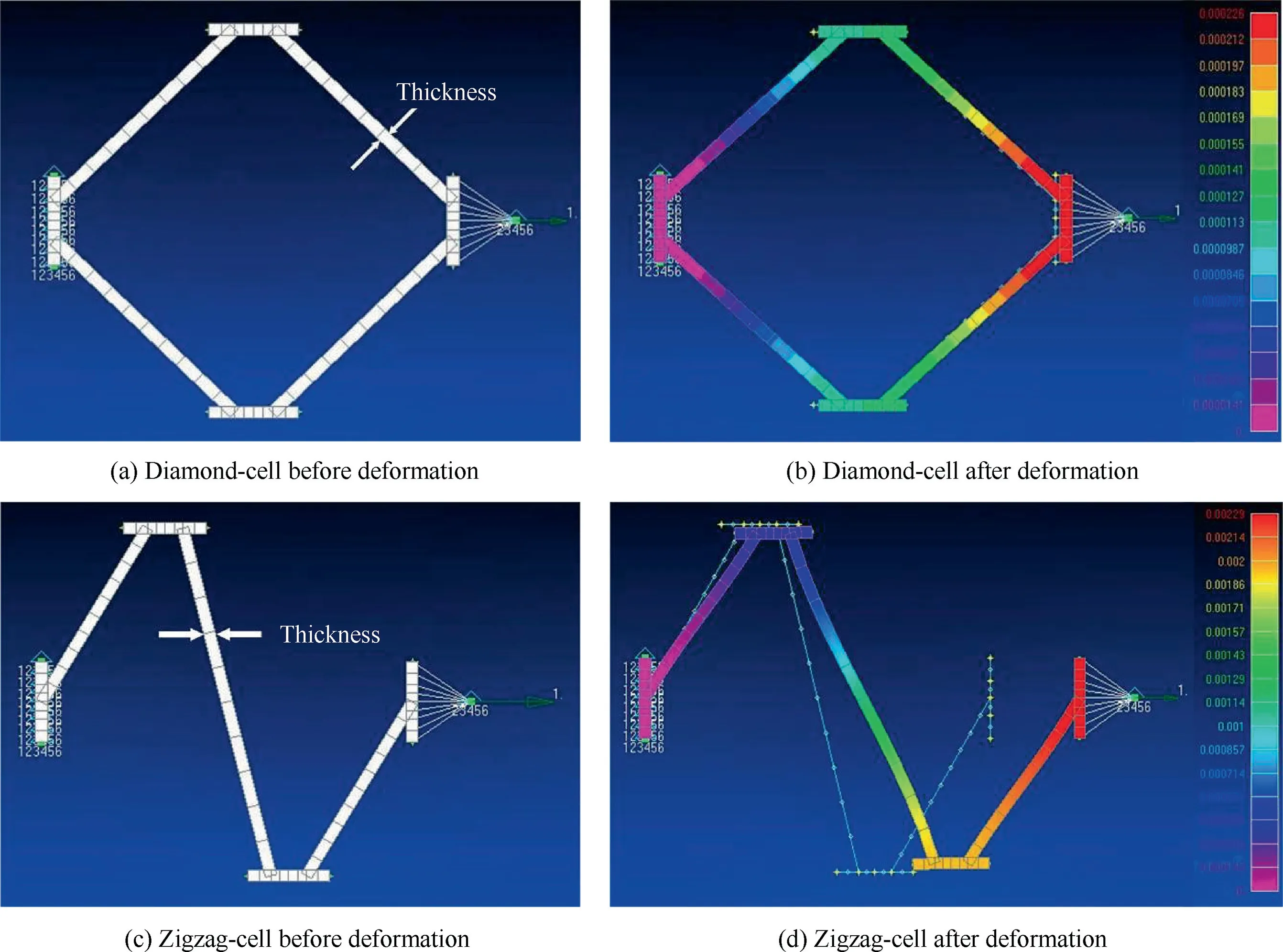
Fig. 4 Diamond cell versus zigzag cell.
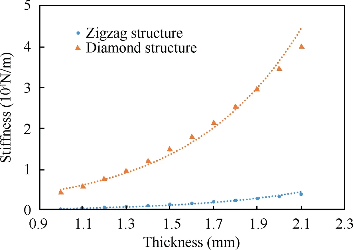
Fig. 5 Stiffness vs thickness of structural elements.
2.4. Sensitivity analysis
The compliant rib considered here has a D-section running from leading edge to 25% chord, zigzag cellular midsection running from 25% to 75% chord and a trailing edge section as shown in Fig. 6. A structural analysis was carried out to determine the effect of the diagonal element’s width and thickness(Fig.6(b))on the rib’s stiffness.The analysis has been carried out under linear-static condition as the strain of rib elements is relatively small. The analysis has been carried out without considering the skin. Three different widths (2.5 mm,5 mm and 10 mm) and thickness (0.5 mm, 1 mm and 2 mm)were considered. The zigzag midsection (of length 125 mm)of the rib has 6 cells as shown in Fig. 6(a). The thickness of the boundary elements (Fig. 6(b)) of the zigzag section is 3 mm.Three types of Finite Element(FE)models were considered to model the rib: solid1. CTETRA (Tetrahedral type)., plate2. CQUAD (Quadrilateral type).and beam3. CBEAM (Line beam type).structural elements. The D-section of the rib is fixed and the force was applied at the rear spar. An additional constraint was applied on the node at which the force is acting in order to avoid the rotation. Fig. 7 shows that the solid model over-predicts the stiffness when compared to the plate and beam models. The beam and plate elements give very close stiffness values. It is speculated that this is because the solid FE model has stress concentrations at the points in the coinciding curves of the structure. Moreover, the solid model has less DOF compared to the beam and plate models. A sensitivity study was conducted for beam (CBEAM) and plate (CQUAD) zigzag elements for mesh convergence. The D-section of the rib was fixed and a force of 9.81 N was applied at the rear spar and the translational value was noted for different mesh size. It can be seen from Fig. 8 mesh convergence occurs when the mesh size is less than 0.003 m.
An experiment was conducted using a 3D printed compliant rib. The tip of the D-section of 3D printed rib was hinged with a bolt and weight was applied at the trailing edge section as shown in Fig. 9. The elongation/translation was measured.The average stiffness obtained from the experiment upon adding different weights was compared with the FE analysis results.Table 1 shows that the FE beam model has more agreement with the experiment.The number of nodes restricting any node in a beam model is less than that of the plate and the solid model. For solid elements, artificial stiffening occurs due to stress concentrations at the points in the coinciding curves of the structure.In addition,the rib elements are of high aspect ratio making beam elements more realistic and representative. This justifies the high accuracy of the beam model in this case. The experiment was repeated three times to confirm validity.
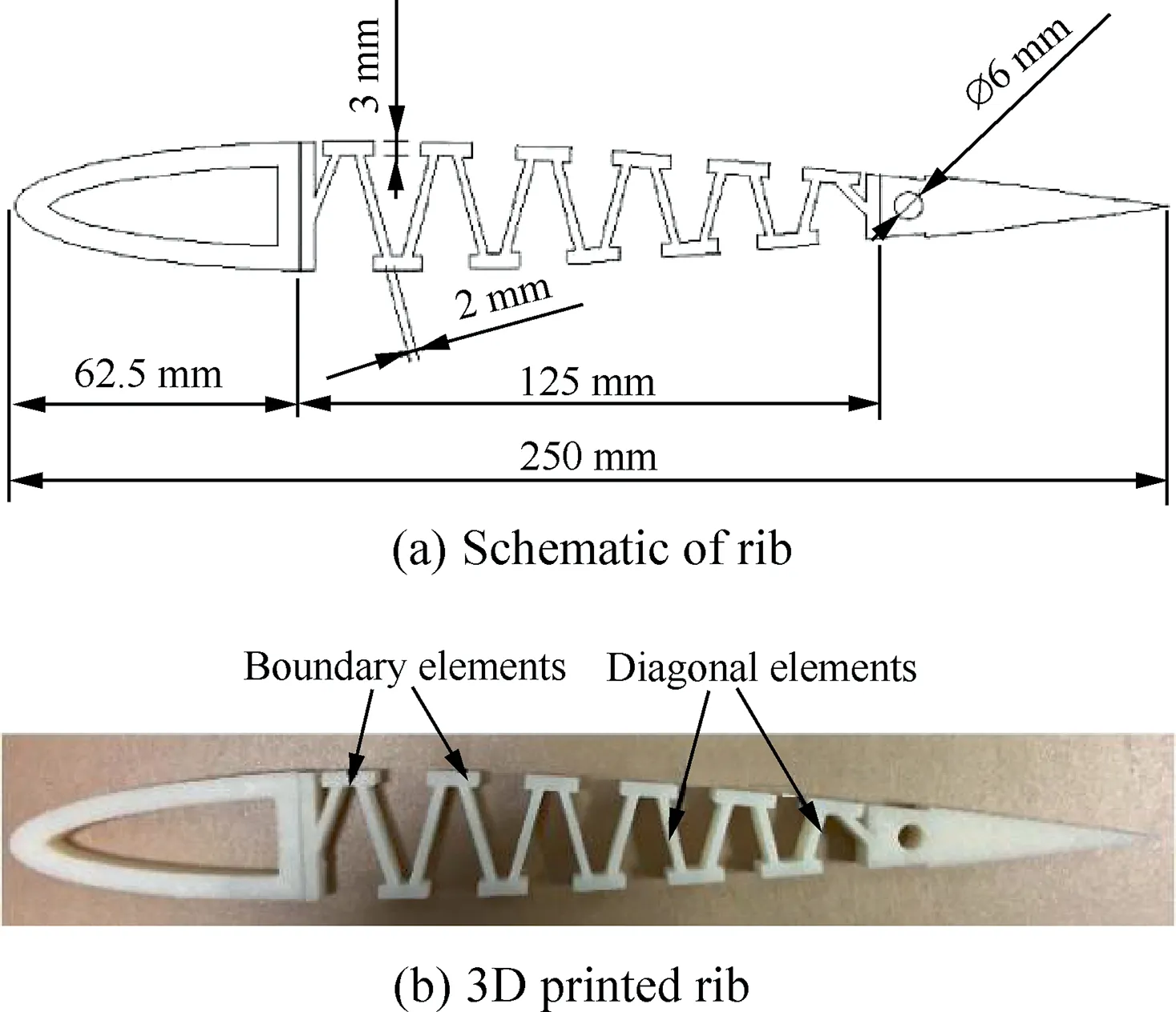
Fig. 6 Rib with D-Spar of 25% chord.
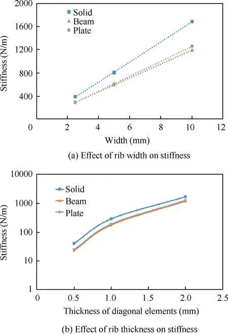
Fig. 7 Effect of rib width and thickness on stiffness.
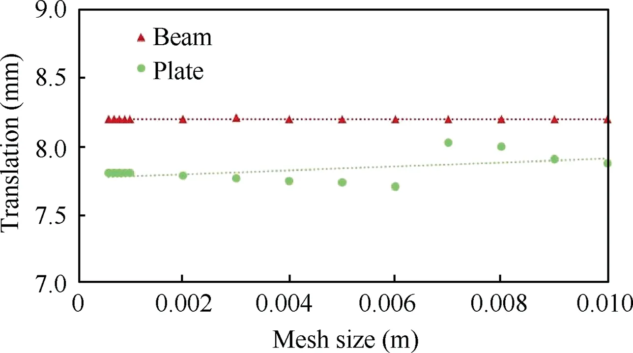
Fig. 8 Mesh independent study for beam and plate elements.

Fig. 9 Experimentation with 3D printed rib.

Table 1 Average stiffness obtained from experiment and analysis.
An analysis has been carried to investigate the effect of the moment on the deflection of the trailing edge(for camber morphing) using plate elements. The moment was applied at the rear spar located at 77.5% of the chord. The width of the rib analyzed was 10 mm and the thickness of the diagonal elements is 2 mm. Fig. 10 shows that a linear relationship exists between the applied moment and the angle of deflection.
2.5. Stress analysis
A stress analysis has been carried out to estimate the factors of safety on the rib when subject to actuation loads. Plate elements were used for the analysis.Tables 2 and 3 show the factor of safety upon chord morphing and camber morphing.The VonMises stress has been considered for the estimation of the factor of safety.It can be seen from Table 2 that chord(of rib with a D-section having 25%chord length)cannot be extended up to 10 %. Therefore, a new compliant rib is used where the D-section is decreased to 15%and the chord of the zigzag cellular midsection is increased to 60% and hence the number of cells in zigzag cellular midsection increases from 6 to 8 as shown in Fig. 3. The stress analysis for the new rib with narrower D-section (15% chord) shows the chord can be safely extended to 10% as documented in Table 3. Tables 2 and 3 show that the rib can achieve ±20° camber changes without any structural failure.
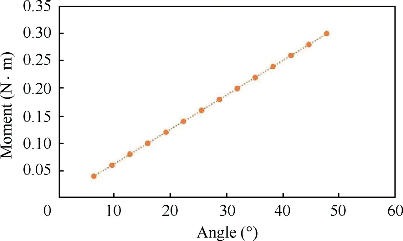
Fig. 10 Moment versus trailing edge deflection.

Table 2 Factor of safety for old rib.

Table 3 Factor of safety for new rib.
2.6. Flexible skin
A latex sheet of 1 mm thickness is used as the morphing skin.The skin is connected to the rib through stringers as shown in Fig.11 and it is bonded to D-section and the trailing edge.The skin is pre-tensioned in chordwise direction to reduce wrinkling from camber morphing at zero chord extension. The wrinkling will be larger at the smallest chord with maximum camber. Fig. 12 shows the stress-strain curve for the latex sheet used in this study.25The Poisson’s ratio of the latex sheet is 0.49 and Young’s modulus can be obtained from Fig. 12 at different strain levels and sheet thickness.
2.6.1. 2D skin analysis
The latex skin was attached to a single rib to determine the pre-tensioning required to avoid wrinkling when morphed.Fig. 13 shows the rib with the attached skin at different pretensioning for 20° camber change. Skin wrinkling associated with camber morphing can be completely avoided at 15%pre-tensioning in the chordwise direction. Fig. 14 shows the rib with 15% pre-tensioned skin at different morphing conditions.
An analysis has been carried out using Femap with NX Nastran to investigate the effect of aerodynamic loading on the deformation of the rib. The analysis is performed at the critical flight condition where the wing is at 10% chord extension and 20° camber change and operating at an airspeed of 20 m/s and an angle of attack of 7°.Four cases corresponding to 0%,5%,10%and 15%skin pretension are considered.For all the cases, it appears that the aerodynamic loads induce an effective change in the camber of the airfoil by shifting the cellular structure of the rib (between the two spars) upward. At 0% pretension the maximum vertical displacement of the rib is 10.4 mm, however for 5% and 10%, and 15% pretensions,the maximum vertical displacement drops to 10 mm, 9.9 mm,and 9.7 mm respectively.Finally,for 20%pretension,the maximum vertical displacement reaches 3 mm. It is clear that pretensioning the skin not only minimizes wrinkling(that will distort the aerodynamic shape) but it will minimize secondary effects and couplings caused by effective camber change under aerodynamic loading.At 0%skin pretension,the bending stiffness of the rib is 87 N/m. It increases with skin pretension to reach 100,112 and 124 N/m at 5%,10%and 15%pretensions.

Fig. 11 Latex skin attaching to a single rib.

Fig. 12 Stress-strain curve for different Latex specimens.25

Fig. 13 Ribs with pre-tensioned skin at 20° camber changes.
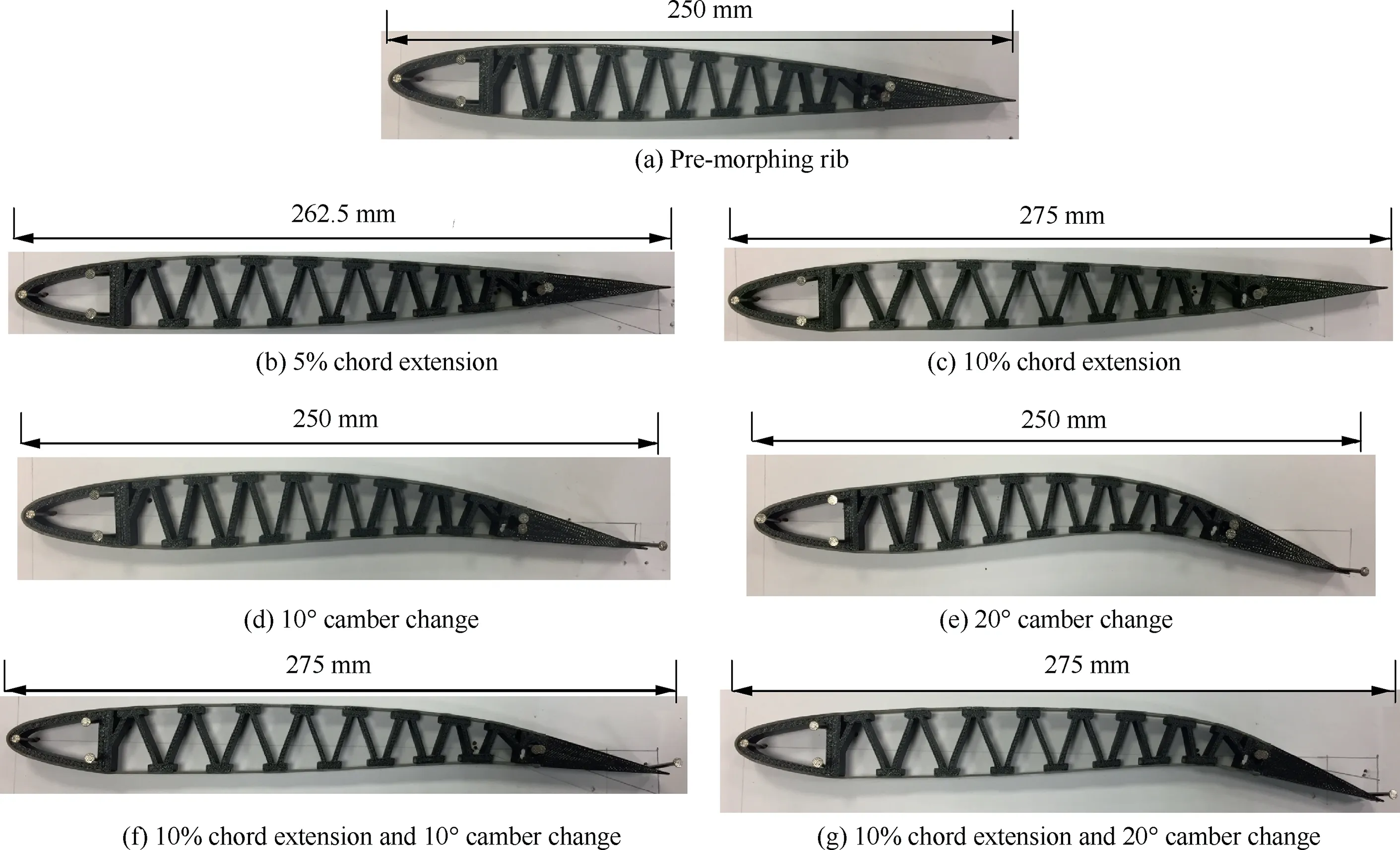
Fig. 14 Ribs with 15 % pre-tensioned skin at different morphing conditions.
2.6.2. 3D skin analysis
The skin with 15% pretension was attached to a section/partition of the wing. The section consists of a wing region bounded by two ribs as shown in Fig. 15(a). Fig. 15(b)shows the section of the wing with the attached skin. It can be seen from Fig. 15(b) that 15% skin pre-tension skin is not enough to prevent wrinkling and out-of-plane deformation due to high Poisson’s ratio of the skin. In other words, although 15% pre-tension was sufficient for the 2D airfoil but it is not sufficient for a 3D partition. Moreover,the large pre-tensioned skin on the section of the wing caused a reduction in the chord by 6.5 mm. Therefore, it is decided to add additional D-sections between the two ribs and extrude the stringers so they run spanwise between the two ribs as shown in Fig. 16. By adding the additional Dsections and stringers, 5% pre-tensioning was enough to avoid the wrinkling in extreme conditions and the out-ofplane deformation.
3. Aerodynamic analysis
Aerodynamic analysis using XFOIL panel method has been carried to investigate the aerodynamic performance of the base(NACA0012)and morphing airfoils.The analytical high-order panel method of XFOIL uses a linear-vorticity stream function to solve for the flow field which produces streamlines along the airfoil boundary. The linear-vorticity stream function method cannot predict the viscous effects on drag as it assumes inviscid flow. Therefore, XFOIL includes a viscous boundary layer component for complete drag prediction.26XFOIL is meant to be used for angles of attack up to and just beyond the stall and small to moderate boundary layer thickness.11XFOIL requires the airfoil coordinates and the flight condition as inputs.11The coordinates of morphed airfoils were extracted from Femap with NX Nastran. The coordinates of the nodes on the deformed rib were extracted and imported to XFOIL.The lift coefficient(CL),drag coefficient(CD),lift to drag ratio(L/D)and coefficient of moment(Cm)were obtained and plotted against the different angles of attack(α).The investigation has been carried out for different airfoils at a velocity of 20 m/s(cruising speed of the UAV) as shown in Fig. 17. The camber as a percentage chord after morphing has been extracted from XFOIL analysis. The airfoil with 10° camber change is equivalent to 3.7%camber change,20°camber change is equivalent to 7.4%camber change,10%chord extension and 10°camber change is equivalent to 3.6% camber change and 10% chord extension and 20° camber change is equivalent to 7% camber change. The chord extension alone will contribute a negligible change in the camber due to small rotation in the zigzag midsection.
3.1. Aerodynamic mesh convergence
A convergence study was conducted to determine the suitable number of nodes for XFOIL. The analysis for the base airfoil(NACA0012) has been conducted at different angles of attack(α) for a velocity of 20 m/s. It can be seen from Fig. 18 that 150-panel nodes are sufficient to generate accurate results with minimal error.
3.2. Aerodynamic results
Fig. 19 shows the variations of CL, CD, L/D and Cmwith the angle of attack respectively. All the coefficients obtained from XFOIL were normalized by a chord of 0.25 m for ease of comparison. Chord extension increases the lift curve slope. The non-zero CLvalue at α=0° for chord morphing is due to small rotations in the zigzag cellular midsection which causes changes in the symmetry of the airfoil. At angles of attack above 5°, the camber morphing increases CLabove that of the base airfoil with plain hinged flap. The airfoil with 10%chord extension and 10°camber change has a higher lift curve slope than the base airfoil with the hinged flap at 10° deflections.For these cases,the stall occurs earlier than the base airfoil and morphed airfoil with chord morphing alone.Similarly,the chord and camber morphing airfoil with 10%chord extension and 20°camber change has higher lift curve slope than the base airfoil with the hinged flap at 20° deflections. For this case,the stall occurs much earlier at α=7°and there is a sudden decrease in CLvalue due to flow separation.

Fig. 16 Section of wing with additional D-sections and stringers.
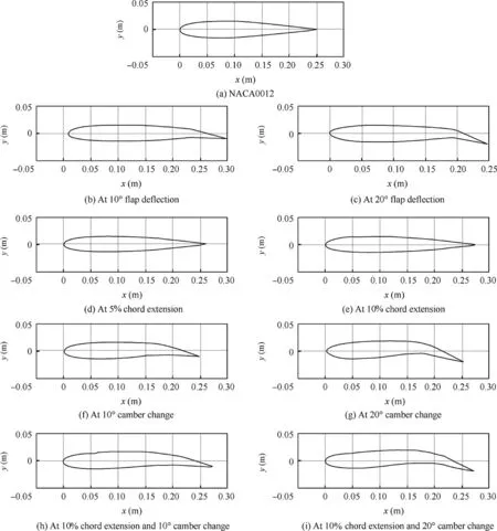
Fig. 17 Airfoils considered for aerodynamic analysis.
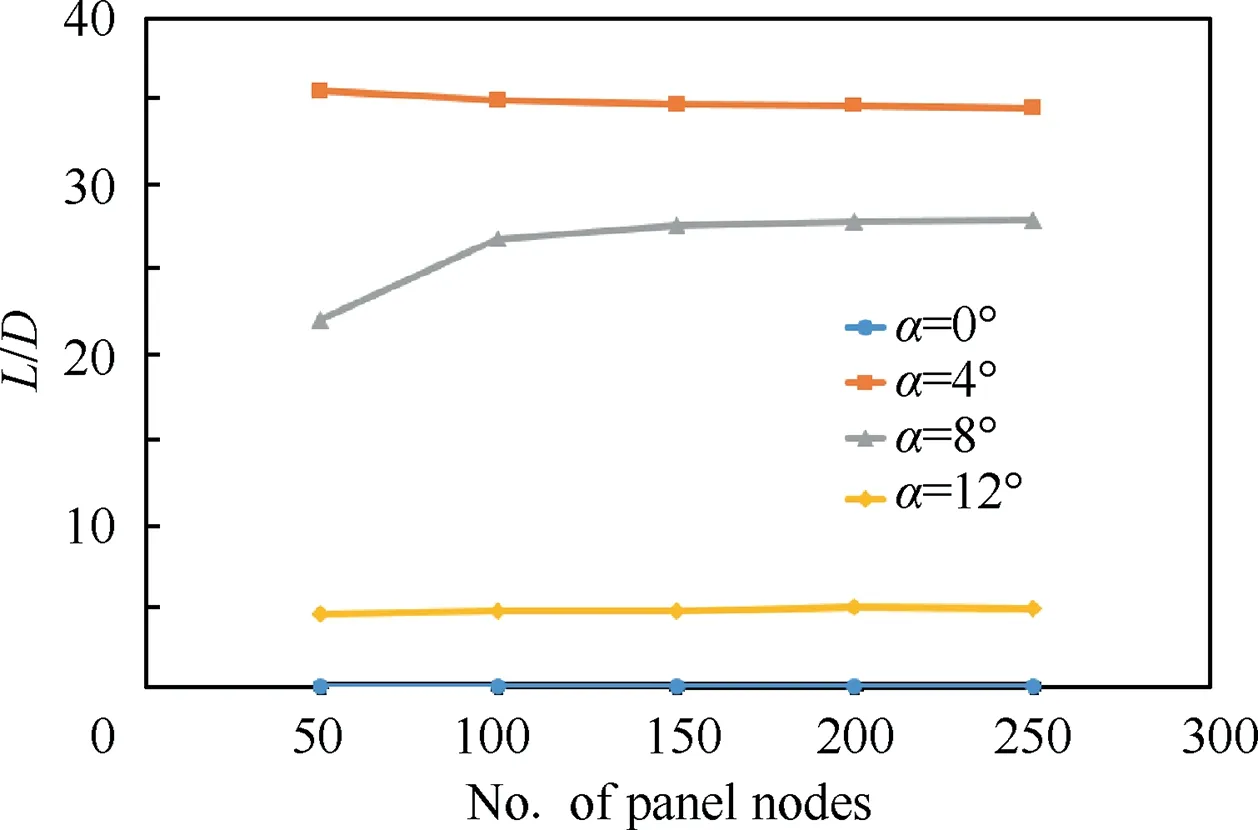
Fig. 18 Panel convergence study for XFOIL analysis.
Fig. 19(b) shows that the chord morphing airfoils have almost similar CDas the base airfoil below α=3°. At angles of attack above α=7°, the camber morphing airfoil with 10° camber change has less drag than that of the base airfoil with hinged flap at 10° deflections. The camber morphing airfoil with 20°camber change has a higher CDvalue than that of the base airfoil with hinged flap at 20° deflections. The chord and camber morphing airfoils have higher CDvalues than the base airfoils with and without hinged flap.
It can be seen from Fig.19(c)that the chord morphing airfoils are aerodynamically efficient than the base airfoil at angles of attack below α=4°. The camber morphing airfoil with 10° camber change has more lift to drag ratio than the base airfoil with the hinged flap at 10° deflections at angles of attack above α=7°. At an angle of attack below α=3°the chord and camber morphing airfoil with 10%chord extension and 10° camber change is more efficient than that of all airfoils studied. The chord and camber morphing airfoil with 10% chord extension and 20° camber change is less aerodynamically efficient than the base airfoil above α=3°. It is speculated that this because of the flow separation due to the angle of attack.
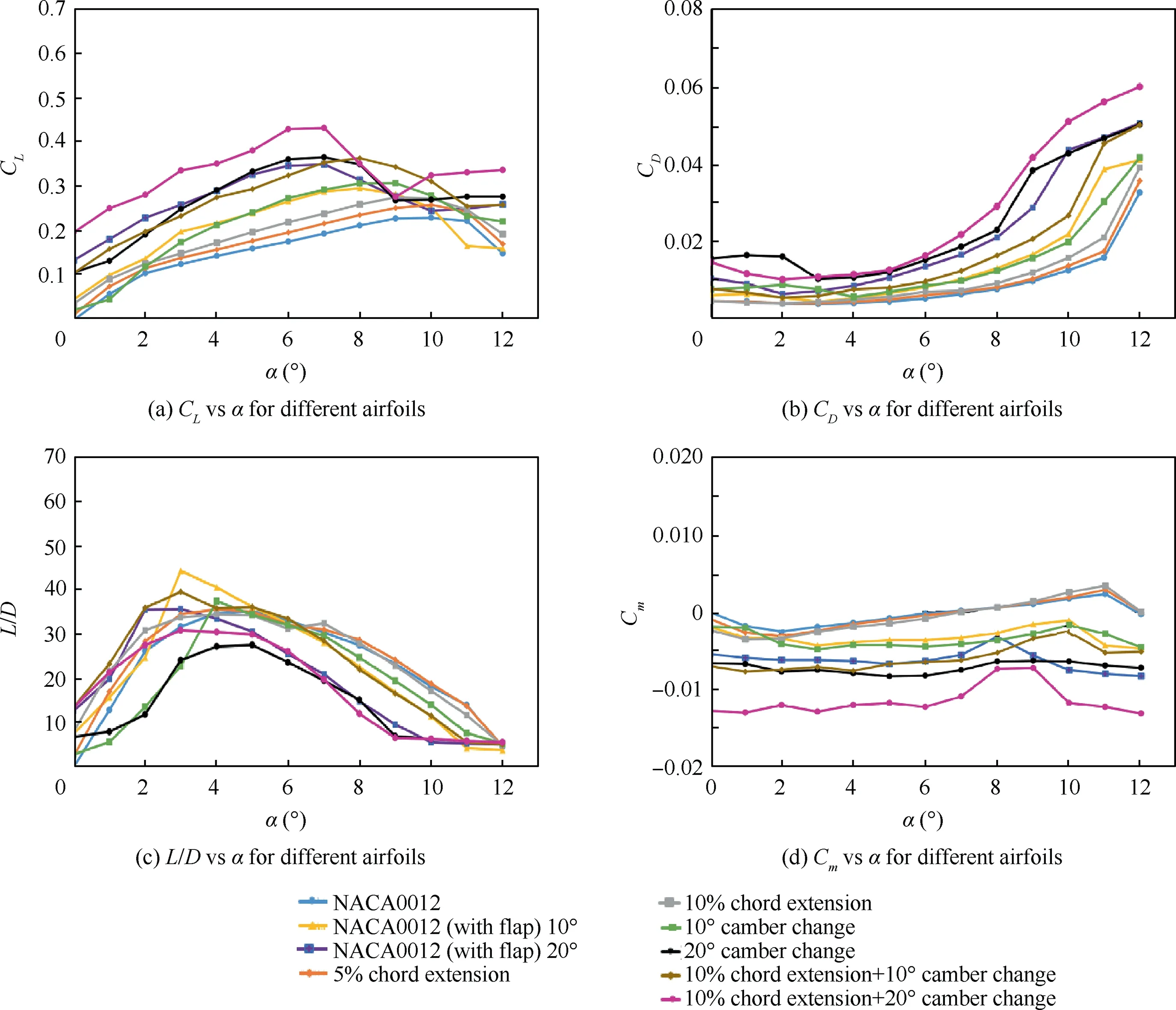
Fig. 19 Variations of CL, CD, L/D and Cm with angle of attack.
Fig. 19(d) shows that the base airfoil and chord morphing airfoils have similar trends in the variation of Cm with respect to angles of attack due to the symmetry of the airfoil.Camber morphing results in higher magnitude nose-down pitching moment. The highest nose-down pitching moment is achieved with 10% chord extension and 20° camber morphing. The large nose-down pitching moment results in a higher trim drag.
4. Actuation and testing
The rack and pinion actuation mechanism is used to facilitate chord morphing.It consists of a rectangular frame which slides using rails fixed on the side-walls of the fuselage.The pinion is driven by a stepper motor fixed to the floor of the fuselage.The rack is housed in a c-channel that is attached to the rail.Camber morphing actuation system is achieved by having the rear spar in the starboard wing and the rear spar in the port wing attached to a stepper. These stepper motors are attached to a rectangular frame allowing the symmetric and asymmetric camber morphing.This arrangement allows camber morphing and chord morphing simultaneously. The rear spar is connected to the stepper motors via bearings so that it can rotate around itself. Fig. 20 shows the actuation mechanism assembled with the central plywood box resembling the fuselage of the UAV. The loads from the rear spar will be transferred to the rectangular frame through the sliding section of the rail and the stepper motors. The aerodynamic load from the skin of the wing transfers to the spar via ribs and the steel rails.
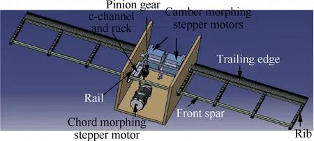
Fig. 20 Actuation system.
4.1. Actuation system
A Nema 23 stepper motor fitted with a gearbox having a gear ratio of 50:1 is used for chord morphing driven by the DM542T module. The motor-gearbox can produce torques up to 25 N·m.A worm gear is attached to the shaft of the stepper motor to drive the spur gear and eventually the pinion.Both the spur gear and the pinion have a pitch diameter of 30 mm and a module of 1.5. The pinion drives the rack to achieve chord morphing. The rack has 80 mm length with 1.5 module and 20 effective numbers of teeth. Aluminum telescopic rails,having 100 mm length and 35 mm width,are used to facilitate rear spar translation and hence chord morphing.On the other hand, Nema 34 stepper motors were used to achieve camber morphing. Each motor has a holding torque of 3.40 N·m. The Nema 34 steppers are driven using the DM860T(I) module. Two Nema 34 were used to allow symmetric and asymmetric camber morphing. A safety factor was applied when sizing the stepper motors to allow for uncertainties in the modeling and experiments conducted.
But she tried to put him off with other statues, though it was no good, and it was not until they had reached the last hall of all that he saw his brother lying on the ground
As stressed earlier,three stepper motors are used to actuate the wing. One stepper is used for chord morphing and two independent stepper motors are used to achieve symmetric and asymmetric camber morphing. Each stepper motor is driven by a separate compatible driver controlled by an Arduino Uno microcontroller. Using a driver for each motor prevents uneven current distributions which will degrade the performance of the motors. The Arduino Uno receives the input commands from the virtual controller (developed in Visual Basic) as a percentage of chord for chord morphing and as an angle for camber morphing. The Arduino IDE code was written to receive the percent chord or degree camber. The Arduino IDE code will convert the percent chord or degree camber to the number of micro-steps and send the signals to the drivers causing the motors to rotate to the corresponding angles.The stepper motor drivers are powered by a DC power supply. The DC power supply has 48 V as the output voltage.
4.2. Test rig setup
A representative rig has been manufactured, assembled and integrated to replicate a small UAV. A wooden frame is used to represent the fuselage of the UAV and houses the actuation system. Plywood was used to manufacture the wooden frame.The sheet thickness of the plywood was 18 mm to ensure the structural integrity of the rig.A Carbon-Fibre Reinforced Plastic (CFRP) beam, whose cross-section is a hollowed square,acts as the front spar. To achieve camber morphing, each side of the wing has its own rear spar. The rear spars are CFRP beam with solid circular cross-section and 6 mm diameter.Each side of the wing has 4 ribs that are equally spaced as shown in Fig. 20. The ribs support the skin and transfer the aerodynamic and actuation loads from the skin to the spars.Each rib consists of 3 main parts:leading edge(D-section),zigzag mid-section and trailing edge. They are 3D printed using ABS plastic. The ribs are bonded to the spars. 3D printed ABS stringers run in the spanwise direction between the ribs to support the latex skin and minimize wrinkling and out-ofplane deformation during and post-morphing. In total, 15 stringers have been used on each side of the wing: 8 on the upper surface and 7 on the lower surface. The stringers are manufactured separately and bonded to the zigzag midsection of the ribs. Latex sheet with 1 mm is used to cover the wing and maintain its aerodynamic shape. The skin is bonded to the leading edge and trailing edge section(rigid)and bonded to the stringers (which are integral part of the zigzag ribs).
The actuation system for chord morphing is housed inside the wooden frame consists of a metallic rack placed inside an aluminum c-channel and attached to the moving part of a telescopic rail. The fixed part of the rail is connected to the front spar.The rack is driven by a pinion gear which is coupled with a spur gear via an aluminum shaft.The stepper motor utilized here requires a gearbox (to provide the required torque for chord morphing)and a worm gear.Therefore,the effective length of the stepper motor is large to fit along the width of the fuselage (235 mm) parallel to the spars. This resulted in the stepper motor being placed along the length of the fuselage as shown in Fig. 21.
There are two telescopic rails inside the wooden frame including the one which is holding the rack and c-channel.These two rails hold another aluminum frame in which the camber morphing stepper motors are accommodated. Fig. 21(b)shows the complete actuation system.The rear spar is connecting to the camber morphing stepper motors via aluminum couplers which are sitting inside a slit on the wooden frame.By the actuation of the chord morphing stepper motors, the couplers along with the camber morphing stepper motors, aluminum frame, and rear spars move backward through the slit to achieve chord morphing. Two wheels were connected to the aluminum frame to support the weight of the camber morphing stepper motors. As the couplers are not hitting the upper or lower surface of the slit on the wooden frame, it can move during chord morphing and rotate during camber morphing without any issue. Figs. 22 and 23 show the assembled polymorphing wing before and after morphing.
The current drawn by the chord morphing stepper motor during chord morphing alone at 10% chord extension is 0.4 A while the current drawn by the camber morphing stepper motor during camber morphing alone at 20° camber change is 0.32 A. A 20° camber change at 10% chord extension, the current drawn by the camber morphing stepper motor is 0.33 A and by the chord morphing stepper motor is 0.41 A. For all the cases the voltage is constant at 40 V.

Fig. 21 Assembly and integration of polymorphing wing.
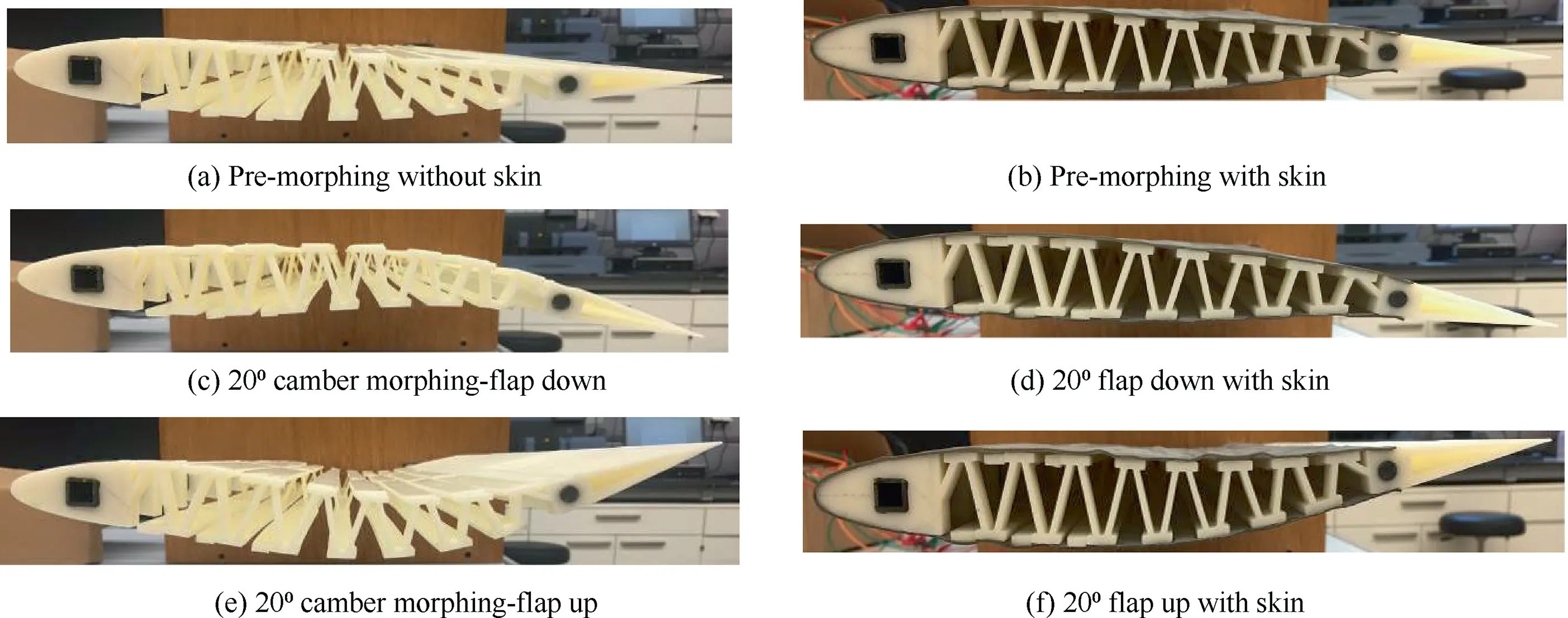
Fig. 22 Wing before and after camber morphing.
4.3. Benchmarking mechanical testing
Extensive mechanical testing was carried out to ensure that the wing can operate in normal and extreme conditions with sufficient structural integrity. Two structural testing, replicating a 1 g and 2.5 g loading scenarios, were conducted. In a 1 g loading scenario, each side of the wing will produce around 25 N lift while in the 2.5 g loading scenario, each side of the wing produce around 62.5 N. In order to simulate these values during benchmarking testing, a static weight is applied at the tip of the wing to generate the same root bending moment and shear force. Using the geometry of the wing, it was determined that 9.81 N applied at the tip and 19.6 N applied at the tip generated the same root bending moment experienced by the wing during a 1 g level flight and 2.5 g maneuver respectively. The wingtip deflection is measured for each scenario at pre and post morphing.Fig. 24 shows the experimental setup to measure the deflection in the wing.
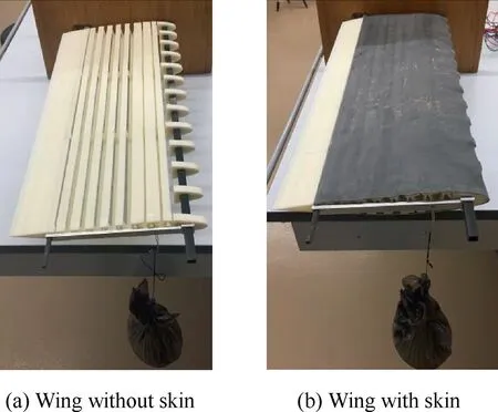
Fig. 24 Mechanical testing of polymorphing wing.
At 1 g loading condition(wing without skin),the tip deflection after 10%chord extension is 1.7%of the semi-span and after camber morphing, it is 1.5% of the semi-span. The deflection before morphing is 1.3%of the semi-span.With skin attached,the tip deflection after 10%chord extension is 1.3%of the semispan and after camber morphing,it is 1.5%of the semi-span.The deflection before morphing is 1.4%of the semi-span.
4.3.2. 2.5 g loading
At 2.5 g loading condition (wing without skin), the tip deflection after chord extension is 3.7 % of the semi-span and after camber morphing, it is 3.3% of the semi-span. The deflection before morphing is 3.3%of the semi-span.With skin attached,the tip deflection before and after morphing did not change much and is around 3.4% of the semi-span.
5. Conclusions
(1) A novel, compliant, polymorphing wing capable of chord and camber morphing has been developed. The wing consists of a front spar that is fixed to the fuselage and trailing edge spar that is allowed to translate and rotate allowing symmetric chord morphing and symmetric and asymmetric camber morphing. The wing is covered by flexible elastomeric skin to maintain its aerodynamic shape while facilitating morphing.Compliant ribs, consisting of rigid D-shape leading edge and a rigid trailing edge connected using zigzag cellular structures,are used to support the flexible skin while morphing and transfer the aerodynamic and actuation loads between the skin and the spars.
(2) Linear structural analysis was performed using Femap with NX/Nastran. Parametric and sensitivity structural studies were performed to study the influence of various geometric parameters of the zigzag structure on the stiffness and strength of the compliant ribs.
(3) Two-dimensional aerodynamic analysis using XFOIL was performed to compare the performance of the morphing airfoil relative to the plain baseline airfoil and the baseline airfoil with hinged flap.
(4) The results of the aerodynamic analysis show that the chord morphing improves aerodynamic efficiency at lower angles of attack while camber morphing improves efficiency at higher angles of attack.
(5) A rack and pinion mechanism powered by a stepper motor is used to achieve chord morphing while camber morphing is achieved by using two stepper motors directly attached to the rear spars of the starboard and the port wings.
(6) Finally, the manufacturing and assembly of a representative test rig are detailed followed by extensive mechanical testing. The mechanical testing confirmed a good level of structural integrity and functional robustness.
6. Future work
The authors are planning a follow-up for this work where wind-tunnel testing will be conducted to accurately assess the aerodynamic performance of the polymorphing wing.Furthermore,aeroelastic interactions due to wing compliance and skin flexibility will be studied.
Different solutions will be studied to overcome/minimize the skin out-of-plane deformations. This includes replacing the front squared spar with the continuous D-spar to maintain the leading edge shape of the airfoil. In addition, biaxial pretensioning and using unidirectional fibers along the spanwise direction of the wing will be used to increase the out-ofplane stiffness of the latex sheet.
Declaration of Competing Interest
The authors declare that they have no known competing financial interests or personal relationships that could have appeared to influence the work reported in this paper.
Acknowledgements
Kamran Khan acknowledges support of Khalifa University of Science and Technology under Research Publication Award(Khan) with Project No. 8474000195.
 CHINESE JOURNAL OF AERONAUTICS2020年10期
- CHINESE JOURNAL OF AERONAUTICS的其它文章
- A novel surrogate modeling strategy of the mechanical properties of 3D braided composites
- A user-friendly yield criterion for metals exhibiting tension-compression asymmetry
- Aerodynamic characteristics of morphing wing with flexible leading-edge
- High cycle fatigue failure with radial cracks in gears of aero-engines
- Motion equations of hemispherical resonator and analysis of frequency split caused by slight mass non-uniformity
- Light weight optimization of stratospheric airship envelope based on reliability analysis
