High cycle fatigue failure with radial cracks in gears of aero-engines
Jie HONG, Liming JIANG, Xiru XU, Ynhong MA,*
a School of Energy and Power Engineering, Beihang University, Beijing 100083, China
b Collaborative Innovation Center of Advanced Aero-Engine, Beijing 100083, China
KEYWORDS Cracks;Fault analysis;Geared rotors;Influences of factors;Response;Unbalance
Abstract The gears in aero-engines perform energy and motion transfer between the High-Pressure Rotor (HPR) and accessories. Firstly, an occurred fault with radial cracks in the driven gear disk was diagnosed as High Cycle Fatigue (HCF) failure through necessary examinations.Analysis of fault tree and test signals indicated that the fracture was relevant to the swing vibration of the driven gear excited by the unbalance excitation on HPR. Secondly, a corresponding mechanism model was established,in which the gear meshing effect was considered,with lateral and swing vibration mode.The Governing Equations(GEs)and the Finite Element Model(FEM)were established and verified. Then, the modal shapes, harmonic response, and transient response were analyzed, indicating that the swing vibration of the driven gear could be significantly excited by the unbalance on HPR, which induced the cracks in the driven gear disk to extend radially. Furthermore, influences of factors on the unbalance response were obtained, in which the unbalance response appeared local minimum points and maximum points.Meanwhile,1#and 2#bearing stiffness had rather significant influences on the response.Thus it is efficient to modify them to achieve vibration control.
1. Introduction
Gears in aero-engines are designed for driving accessories,and the gear train that connects the rotor to the accessories is called the central gear train for the convenience of description, as shown in Fig. 1, which is in a type of aero-engines, belonging to spiral bevel gears. Gear meshing between the driven gear and the driving gear causes coupling between the vibration behavior of High-Pressure Rotor(HPR)and that of the driven gear rotor, which may induce harmful vibration to the operation. A relevant fault has occurred, and the driven gear was broken related to swing vibration mode, presenting two radial cracks in its disk. Therefore, this paper aims at analyzing the fault features and revealing its mechanism.
Researches on cracked gears have been extensively concerned about, along with the dynamic analysis of geared rotors. Relevant studies1-6have been focused on crack propagation prediction, time-varying mesh stiffness calculation,and vibration response calculation with cracks. Cracks studied in gears are either along the tooth root or the rim.And researches have been mostly focused on the spur gears.Although the spiral bevel gears have also been investigated,the related paper is fairly limited. Only a few studies involved spiral bevel gears and helical gears, to the best of our knowledge, are found.However, these studies7-10have been mainly focused on the vibration properties of spiral bevel geared rotors in axial, lateral, and torsional directions, in the absence of researches on radial cracks in the gear disk relevant to swing vibration mode.
Researches on dynamics of geared rotors are based on a single Degree Of Freedom(DOF)models or multi-DOF models,in aim at analyzing linear vibrational properties or nonlinear vibration behavior, focusing on gear meshing stiffness,vibration properties, and vibration control methods.11Theoretical analysis and experiments show that the vibration of geared rotors are nonlinear and time-varying.12The nonlinear features are mainly caused by the backlash between teeth tips,and the time-varying behavior is mainly due to the change of contact ratio with time. Wang et al.13have reviewed the nonlinear vibration of geared rotors in detail,including basic concepts, mathematical models, solving methods, and dynamical behaviors.
A large body of papers has considered diverse nonlinear factors, mainly focusing on the nonlinear and time-varying meshing stiffness caused by the backlash between teeth tips,14the friction of tooth contact15and transmission errors.16,17The nonlinear models established by Kahramanand and Singh18have accounted for the torsional vibration of the shaft. Ozguven19have considered bending-torsional coupling vibrations in their models. Furthermore, Blankenship and Singh20have established a full DOF model for three-dimensional gear rotors to study the coupling and nonlinear behavior.Although nonlinear models have been used in the theoretical study of geared rotors,they have been mainly focused on nonlinear factors and their contributions to nonlinearity.Thus,it is not necessary to apply a nonlinear model for analyzing some specific problems. Linear models have been used extensively in engineering fields, with some advantages, such as solving easily and explicit results. The early study of geared rotors based on linear models can refer to the detailed review of Ozguven and Houser.21Recently,analytical methods and finite element methods have been used for vibration analysis of spur or helical gears,22planetary gears23and the geared rotors with various structures such as bevel geared rotor-bearing system.10
Literature shows that many scholars have obtained significant achievements in the modeling,solving,and analysis methods of dynamics and cracks of geared rotors. However, they might not reveal the underlying mechanism of the fault to be studied in this paper. Performed studies have been mainly focused on spur gears, helical gears and some specific bevel gears, while not suitable for analyzing the central gear train associated with the specific bearing-rotor system. Besides,above studies involving in dynamics and cracks have been mainly focused on the vibration properties of spiral bevel geared rotors in axial, lateral, and torsional dimensions, without considering the radial cracks relevant to swing vibration.Therefore, this paper aims at revealing the underlying mechanism for the failure in view of swing vibration of the driven gear caused by unbalance on HPR,and provides a significant reference for relevant study and application in some special situations. In the first part, a briefly fault analysis combining necessary examinations, fault tree, and test signals has been presented to find the underlying cause. In the second part, an abstract geared rotor-bearing system has been established and analyzed to verify the underlying cause.Furthermore,the influences of factors have been studied to promote suggestions.
2. Fault analysis
The aero-engine, shown in Fig. 1, has experienced excessive vibration during its test operation, and the driven gear of the central gear train was broken repeatedly with radial cracks,which has seriously affected its safe operation.Based on necessary inspections, fault tree, and test signals, this part focuses on the fatal fault, in order to find the underlying causes.
2.1. Examinations and the fault tree
A series of examinations have been performed to obtain the possible causes of the fracture, including the careful macroscopic inspection and the microscopic inspection.
For the failed gear in a test, the overall appearance of the driven gear broken is as shown in Fig. 2. There are two main cracks in the gear disk, marked as 1# and 2# crack, which are about 180° symmetrically distributed and have penetrated the disk.The length of 1#crack is about 30 mm,with the width of 6.5 mm, extending radially from the rim to the center of the disk, penetrating through the corresponding oil hole and extending along a spline. The length of 2# crack is about 4.5 mm,with the width of 1 mm,extending radially to the corresponding oil hole. Besides, there existed fracture in some tooth bodies, and it was very possible that the tooth fracture was a secondary failure caused by the radial cracks. After the radial cracks occurred, the engagement was extremely bad, which caused to severe abrasion on the tooth and even fracture on some tooth bodies.
For the cross section of 1# crack, the macroscopic and microscopic features of this crack are shown in Fig.3.The features of the extension region can be recognized obviously,and the extension path is signed by the dash curve C with an arrow.Two small regions,marked by A and B,are magnified.Region A describes the features of the initiation region without material defects found, and region B describes features of extension,which present typical features of High Cycle Fatigue(HCF).
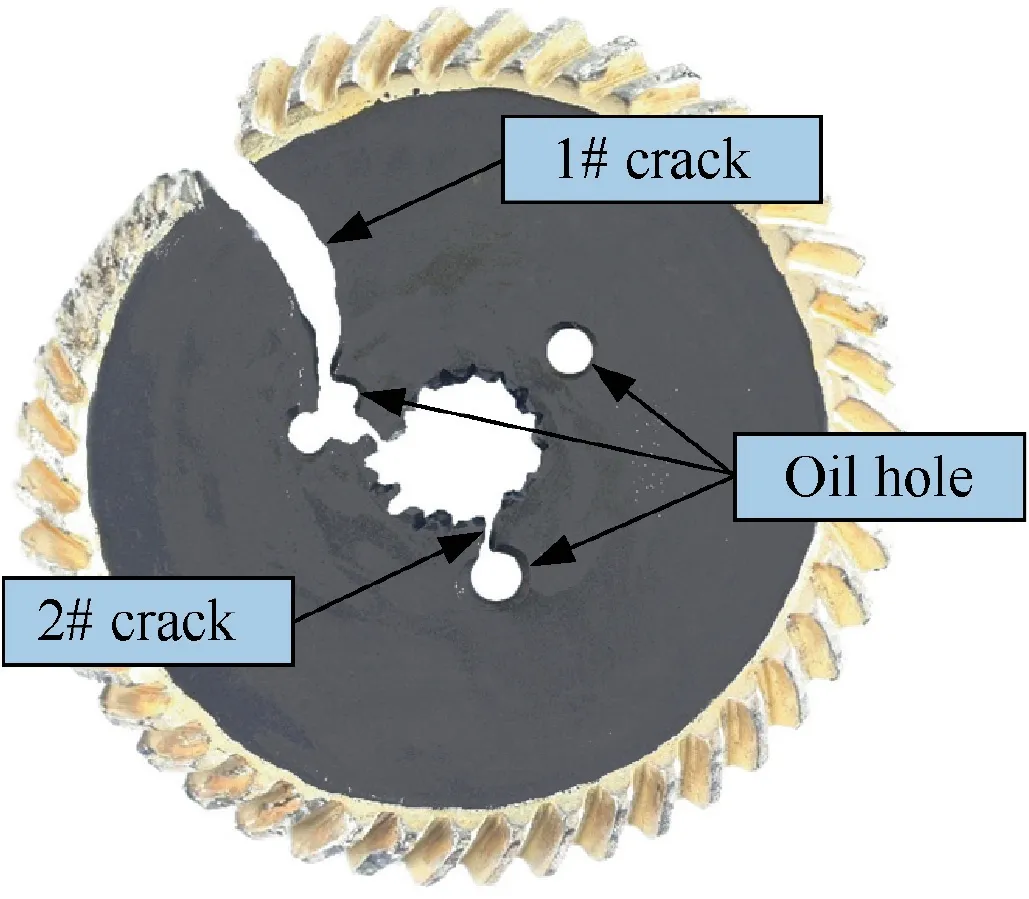
Fig. 2 Overall appearances.
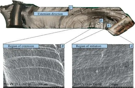
Fig. 3 Features in macro-inspection and micro-inspection.
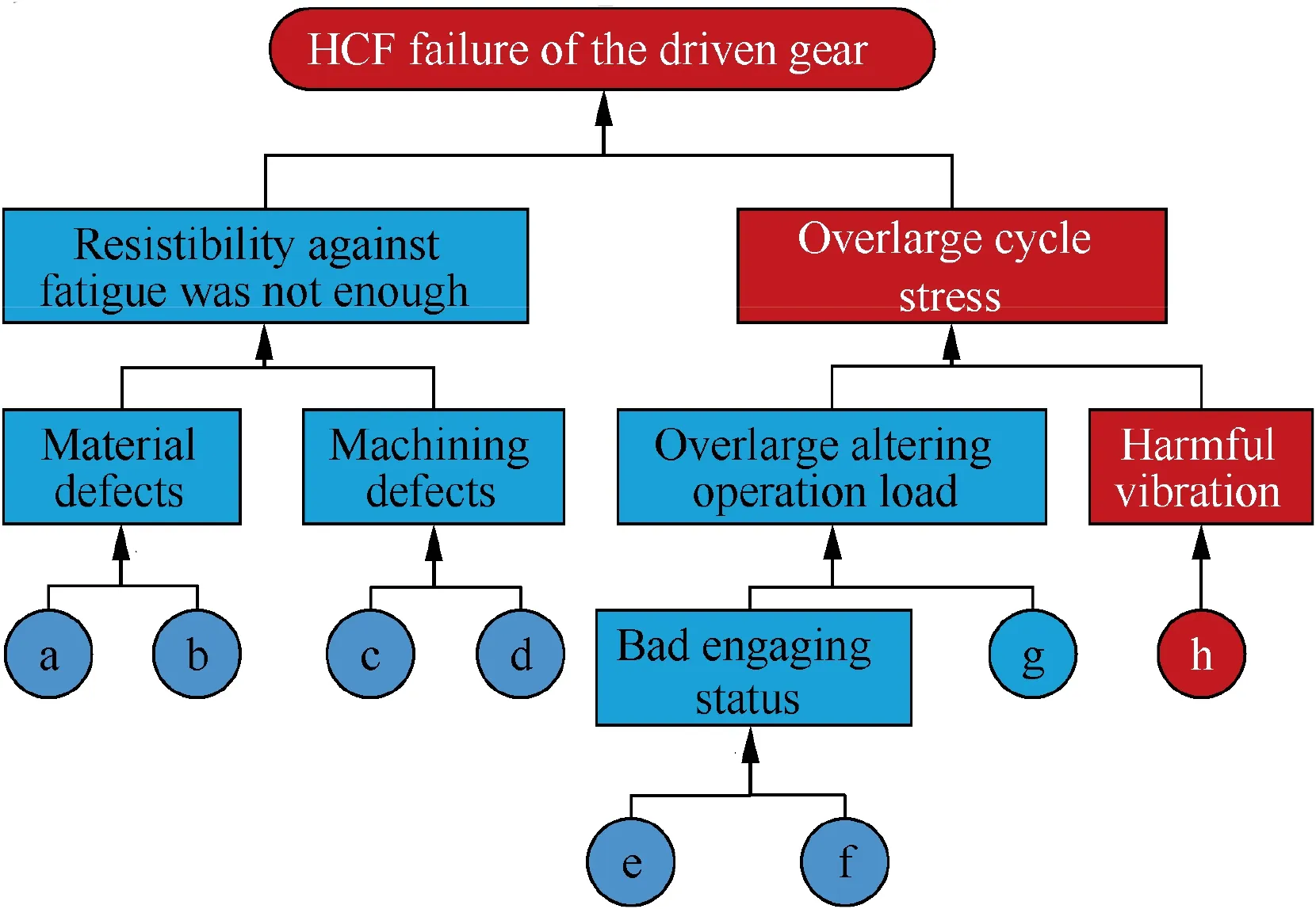
Fig. 4 Fault tree for HCF failure of driven gear.
Other necessary metallurgical examinations have also been performed,which demonstrated that the chemical composition and hardness met the design requirements.Besides,there were no defeats detected for mechanical mark, poor surface finish,initial flaw, or heat treatment.
The fault tree containing basic events for revealing the potential causes of the fracture is shown in Fig. 4, in which the letters represent:a.chemical composition did not match;b.hardness did not meet the design requirements;c.mechanical mark,or initial flaw existed;d.poor surface finish or poor heat treatment; e. geometric errors; f. assembling errors; g. overlarge design stress; h. overlarge forced response.
As for a, b, c and d, these four basic events were denied through the above examinations of failed gears. As for e and f,these two basic events may have caused bad engaging status;however, according to the examination records before experiments, the geometric and assembling errors met the requirements. As for g, a FEM of the driven gear was used to obtain the stress distribution, which showed that the stress level far met the requirement. Briefly, the maximum Vonmisses stress was about 615 MPa at the center of the gear disk,which was far below the yield stress of the material (about 1110 MPa). Besides, the maximum stress at the root of the tooth was just about 150 MPa. As for h, the experiment was performed to obtain the vibration signals, which is analyzed in the following.
2.2. Test signals
The test has been performed using the other specimen with the same batch as the failed ones.The rotational speed of HPR in the test was remaining at 36900 r/min,in which speed,the test was performed for 169 s. The sampling frequency in the test was 10000 Hz, which was good enough for the FFT analysis,with the range of 0-2000 Hz. There were two main measuring points set on the specimen for collecting the necessary vibration response. One measuring point was set on the bearing of driven gear(3#bearing)in the direction of x,and the other one was set on the bearing near turbine disk(2#bearing)in the direction of x, as shown in Fig. 1, marked by the letter A and letter B.In the test,1#bearing and 2#bearing shared the same supporting stationary, while 3# bearing was on the other one.
Frequency spectrums of the vibration signals of measuring points during the stable operation were obtained using the Fast Fourier Transform (FFT) method, as shown in Fig. 5.There are two peaks with 2000 Hz in subfigure a) and b) of Fig. 5. According to frequencies of the peaks, the two peaks were defined as and to the frequency 615 Hz,which was corresponding to the rotational speed of HPR. Vibration amplitudes of measuring points A and B had the same magnitude for both the peak and peak. The two peaks indicated that the excitation forces were closely relevant to the unbalance of HPR and its potential misalignments causing component.Besides, other components in the signals might be relevant to airflows, meshing frequency, and so on.
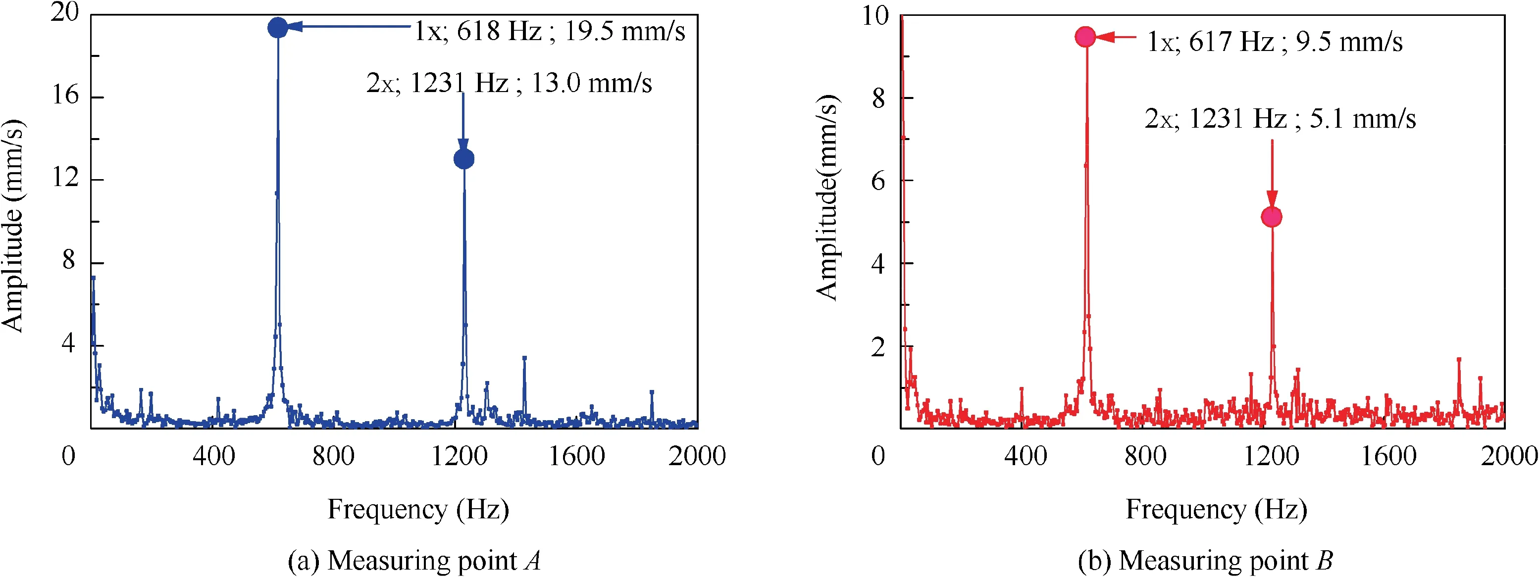
Fig. 5 Frequency spectrums of vibration signals in measuring point A and B.
Therefore, the conclusion that the unbalance excitation on HPR and its excitation have excited the vibration of the driven gear and caused the cracks to expand radially, resulting in the occurred HCF failure, was drawn finally. In the following, a mechanism model was promoted to reveal the fact that the cracks in the driven gear might extend radially with swing vibration mode caused by HPR.
3. Coupling vibration model of geared rotor-bearing system
In this part, an abstract mechanism model for coupling vibration and its GEs and FEM were established. The coupling between the driven gear rotor and HPR caused by meshing effect can be simulated using specific springs.
3.1. Simplification
Since the occurred fault was most likely related to the swing vibration of the driven gear, this paper mainly focuses on the bending vibration of the HPR and the swing vibration of the driven gear. Thus, DOF in the directions along the transverse direction x of the HPR and that direction of the driven gear rotor were considered merely, when it comes to considering the meshing effect. Therefore, the simplified model is shown in Fig.6,in which,O-xyz is the local Cartesian coordinate system of HPR, and O′-x′y′z′is the local Cartesian coordinate system of the driven gear rotor.
The array of all generalized DOF corresponding to the stationary coordinate,including the deflection caused by bending of shaft,swing displacement of disks due to shear deformation and the torsion of the established model, is
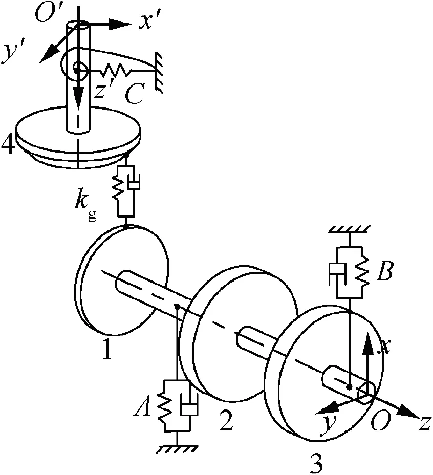
Fig. 6 Mechanism model.

where, i=1,2,3,4 respectively, denotes the driving gear disk,the high-pressure compressor disk, the high-pressure turbine disk, and the driven gear disk. The displacements are represented by x,y and z,respectively.As shown in Fig.7,the angular deflection displacements of the shaft about the respective axis y and x at the geometric center of the disk are represented by θyand θx, and the angular swing displacement of the disk respect to its shaft about the axis x and y are denoted by γyand γx, respectively while φ represents the angular displacement of torsion, which is neglected in this study.
As shown in Fig.1,the shaft of the driven gear in this gear train is too short to bend, and the bearing stiffness is strong enough. Thus its bending stiffness is very high. Namely, the bending vibration of the shaft is difficult to occur. However,the angular stiffness due to shear deformation of the position where the driven gear disk and its shaft was connected is respectively weak.As a result,the swing vibration of the driven gear disk respect to the shaft is easy to occur.So that,the simplified model to be established takes the swing displacement respect to the shaft of driven gear into account, so that its shear deformation is accounting for its angular displacement.
According to Timoshenko Beam Theory,24the angular stiffness for shear deformation is obtained by

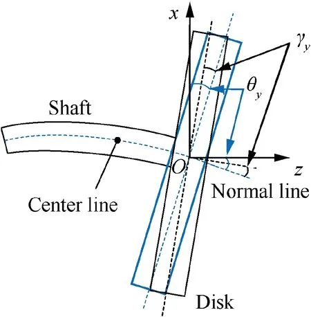
Fig. 7 Angular displacement of bending θy and swing γy.
where, G is the shear modulus; A is the cross-sectional area of the section uniformly;L is the length of the shaft;and κ is the shear coefficient related to the shape of the cross-section,which is taken as 0.9 for solid circle sections, and the details can be found in Ref. 24.
3.2. Governing equations
According to the above analysis and assumptions, GEs of the HPR were derived firstly, based on the Lagrange method, the lumped parameters method, and the Euler beam theory.
The two flexible supports are linear springs with masses mAand mB, respectively, and the bearing stiffness is kAand kB.The mass, pole moment of inertia and diameter moment of inertia of the three disks are mi, Jpiand Jdi, respectively, in which i=1,2,3 denotes the index of the disks.The axial length of the HPR is as shown in Fig. 8.
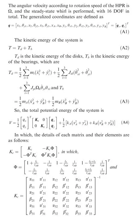
The angular velocity according to the rotation speed of the HPR is Ωh, and the steady-state whirl is performed. The generalized coordinates are defined as
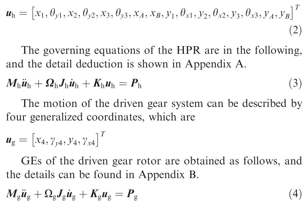
The GEs of the geared rotor-bearing system are finally obtained by connecting springs corresponding to the meshing effect. Although the meshing stiffness is three-dimensional,for the convenience and without loss of generality, it is assumed that the meshing effect occurs in the direction of x axis for the HPR and the driven gear shaft(x′), thereby,causing coupling vibration between x1and γy4,as well as,coupling vibration between θy1and x4. The coupling effect is transmitted through the spring forces,and the component of the meshing force in the direction acting on the driving gear is

In which,kgx1is the meshing stiffness,and r4is the radius of the driving gear disk. Symbols in the following Eq. are analogous.
The corresponding torque imposed on the driven gear in the direction θy4is -fgx1r4;
The component of the meshing force acting on the driven gear in the direction x4is

Fig. 8 Axial length of HPR.
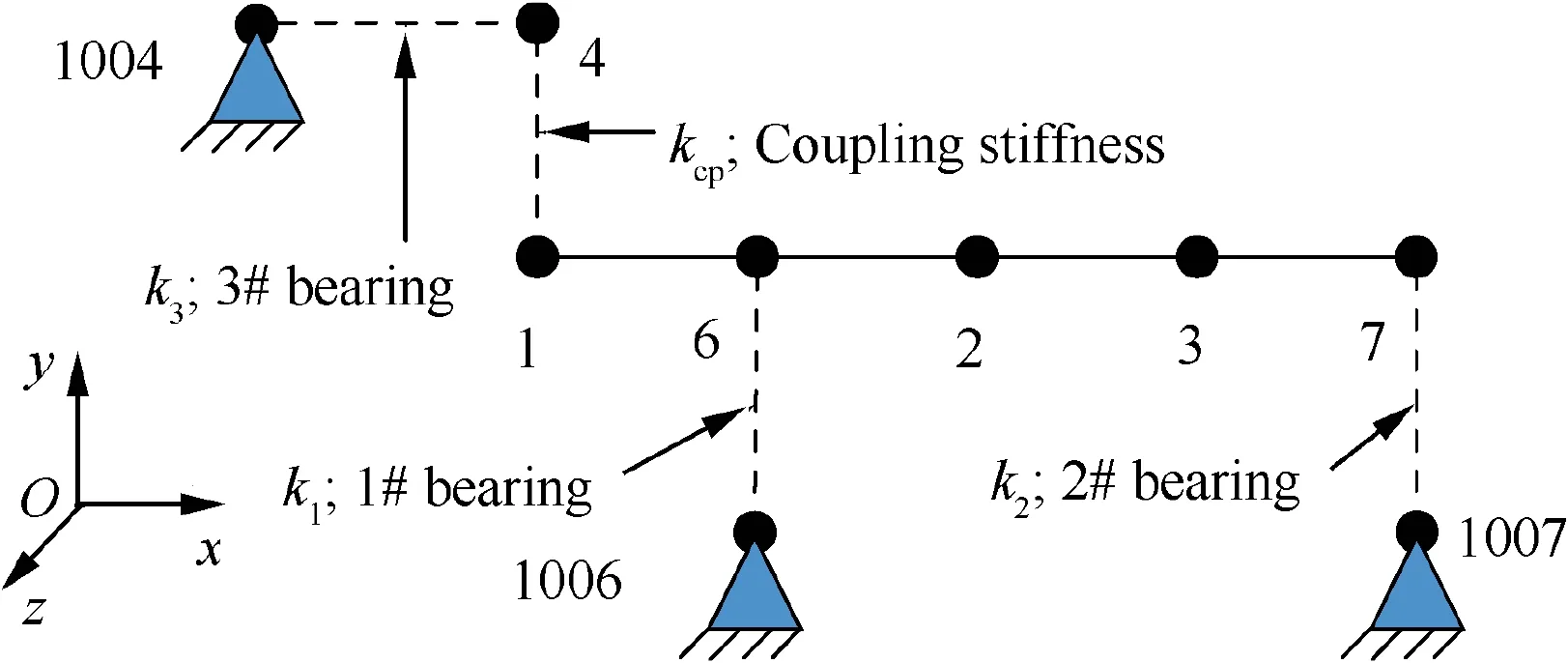
Fig. 9 Finite element model of gear-rotor-bearing system.
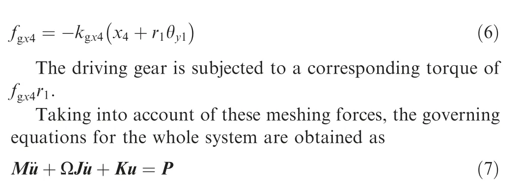
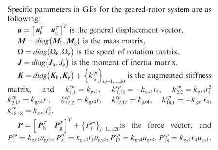
In which, u is the general displacement matrix, M is the mass matrix, Ω is the rotating speed matrix, J is the moment of inertia matrix, K is the augmented stiffness matrix, P is the force matrix, and the details are in Appendix C.
3.3. Finite element model
The FEM was established by the software Ansys18.0, as shown in Fig.9,which was used to verify the governing equations and in return of itself.Furthermore,it was applied to perform unbalance response analysis.
The FEM includes nodes 1, 2, 3, and 4 representing the disks, nodes 6 and 7 representing the bearing supports, and corresponding fixed nodes 1004, 1006, and 1007 representing the stationary. The nodes of HPR are connected by BEAM4 beam elements, and the bearing supports are stimulated by the COMBIN40 spring elements.In order to consider the coupling effect between the DOF of nodes representing the driven gear and the driving gear, the connection between the node 1 and the node 4 is performed by the element MATRIX27,and the nonzero elements of its parameters are given in Table 1.
4. Coupling vibration properties
In this part,without loss of generality,an example with values in Table 2 was given for simulation.
4.1. Verification of GEs and FEM
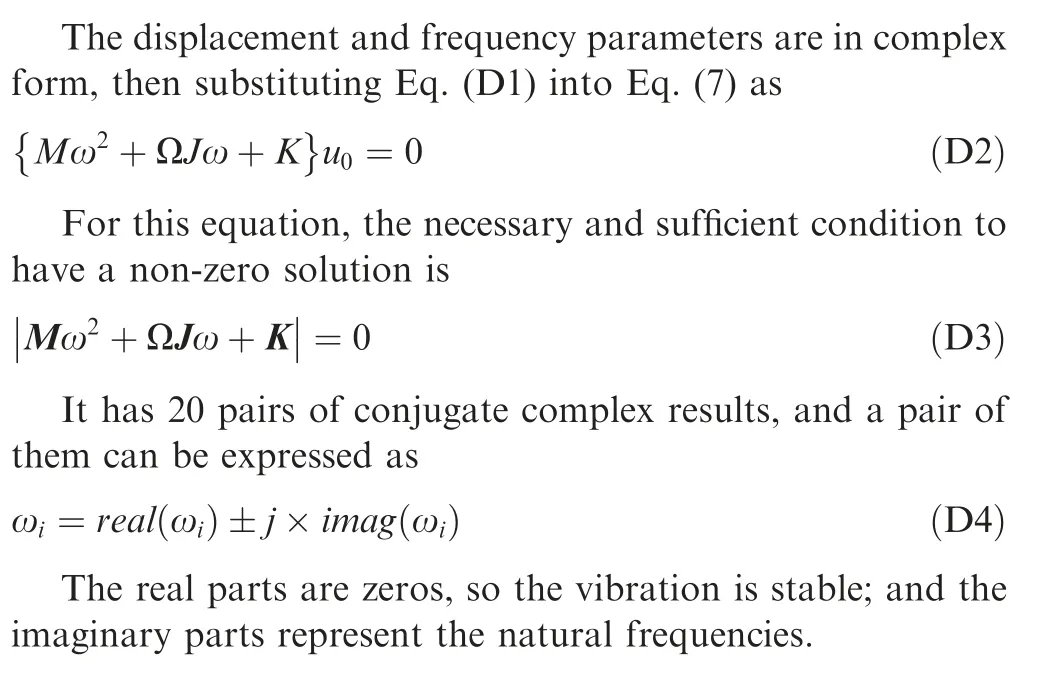
In order to verify GEs and FEM,all of the natural frequencies were calculated by GEs and FEM respectively, and the comparison for the differences was performed. The method used to solve the Eq. (7) for obtaining the natural frequencies and modal shapes is given in Appendix D. For the FEM, the QRDAMP method in the modal analysis was applied. The comparison between the results is shown in Fig. 10. The maximum difference computed by Eq.(8)of all the frequencies was less than 0.3%,which verified the GEs and FEM without modeling errors.

Table 1 Nonzero parameters of the MATRIX27 element.

Table 2 Values of example for geared rotor-bearing system.
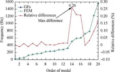
Fig.10 Comparison of natural frequencies obtained by GEs and FEM.

In which, means frequencies obtained by the GEs.
4.2. Modal analysis
Since GEs and FEM coincided with each other,and FEM has the advantages of simplicity, quickness, and convenience in solving linear problems, the solution in the following parts was based on FEM.
The influences of meshing effect on the vibration properties were analyzed through modal analysis. As not all DOF are concerned about too much, it is not necessary to list the full results of modal analysis. Namely, we are concerned about the γy4mostly, thus the relative amplitudes of γy4to the maximum amplitude for each modal shape, namely normalized by the maximum amplitude, are given in Table 3.
The amplitude of the rotational displacement of the driven gear in some modes is zero,but the amplitude is not zero anymore,considering the coupling effect.In the 3rd,5th,6th,7th,9th,12th,13th and 14th modes,the amplitude of γy4is nonzero considering the meshing effect.Moreover,the natural frequencies corresponding to these mode shapes are likely to near the operational rotation speed of the rotor. Thus, swing vibration of the driven gear can be excited by unbalanced forces on HPR, which might have induced the crack to extend radially.
4.3. Harmonic response to excitation of unbalance
Assuming that the eccentric mass was on the HPR, on the compressor disk for specific, and its magnitude was given in Table 2. The damp ratio was set to 0.001 (by DMPSTR command), which was for the convenience of calculation without altering the intrinsic properties significantly. There is not necessary to list results of all DOF,showing the amplitudes of the frequency response of γy4,x3and y3,for comparison with corresponding test signals,which denote the angular displacement about the y axis of the driven gear disk and the displacement of the turbine disk along the x axis and y axis, as shown in Fig. 11.
According to Fig. 11, considering unbalance on the compressor, the vibration response of the γy4coincides with the responses of the x3and y3for many peaks, especially the six rather high peaks which are remarked by letter A, B, C, D,E, F (peaks D and F are magnified locally). Meanwhile, it is obvious that the unbalance on the HPR can not excite the vibration of the driven gear, if the meshing effect is unconsidered, as the driven gear rotor and the HPR are separated.Thus, the conclusion that the swing vibration of the driven gear such as vibration in direction of γy4shares the same resonance frequencies with the HPR for unbalance excitation on the compressor, which indicates that the swing vibration of the driven gear can be significantly excited by the unbalance forces on HPR. This has been verified furthermore by the transient response analysis under the operational condition,revealing the same features with test signals.Besides,there are some regions where the response could be controlled at an extremely low level, relevant to anti-resonance frequencies.25This can be applied for vibration control by structural modification,26,27though it could be expensive to obtain antiresonance features for a complicated system.
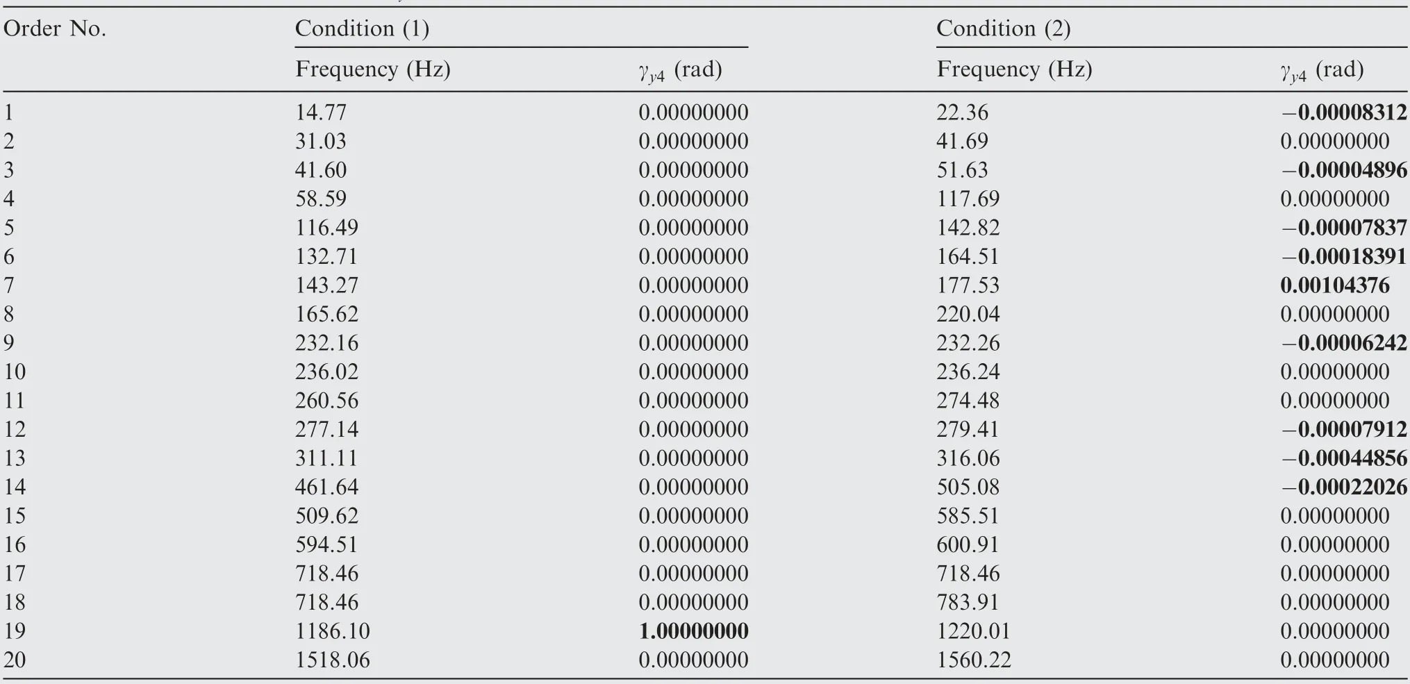
Table 3 Angular displacements of γy4 for each modal shape.
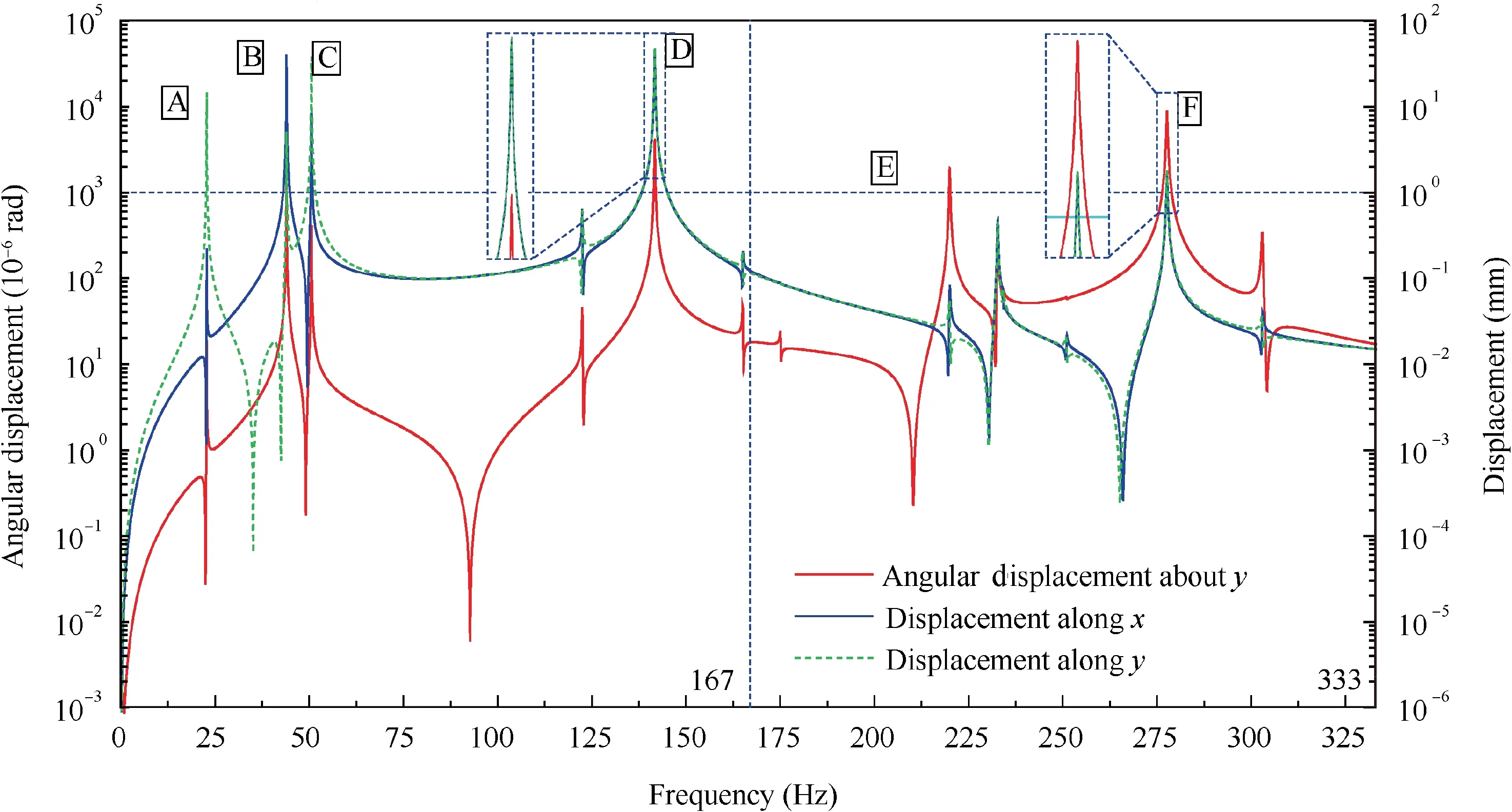
Fig. 11 Frequency response of γy4, x3 andy3 to unbalance excitation on HPR.
4.4. Transient response to excitation of unbalance
The simulation model was the same as that in Section 4.3,and the rotation speeds ware set constant according to Table 2.Meanwhile, in order to dissipate the transient term more rapidly, the damp ratio was set as 0.05. Displacements of the turbine disk in two transverse directions are as shown in Fig. 12, in which it is approximately stable enough for the forced vibration term when time is beyond 0.9 s. The stable orbit of the turbine disk centroid is shown in Fig. 13, which is approximately a circular trace. In the current stable stage,the orbit in direction of x is more stable than that in the direction of y, which is due to the asymmetry.
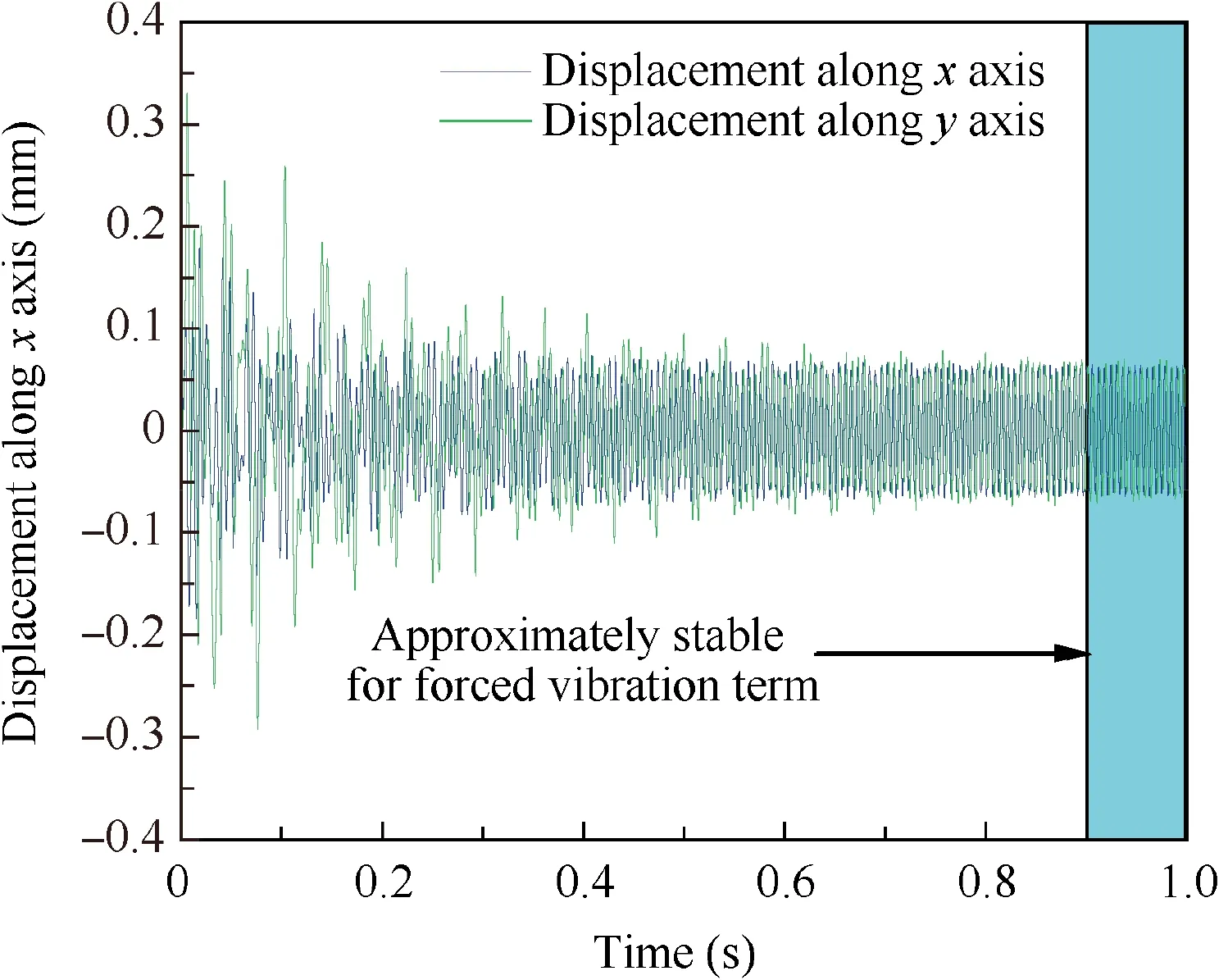
Fig. 12 Displacements of turbine disk.
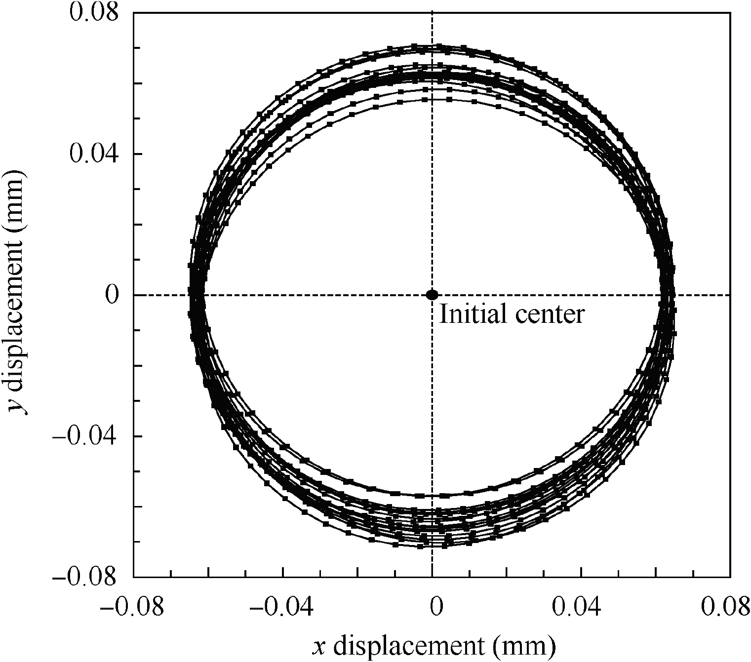
Fig. 13 Stable orbit of turbine disk.
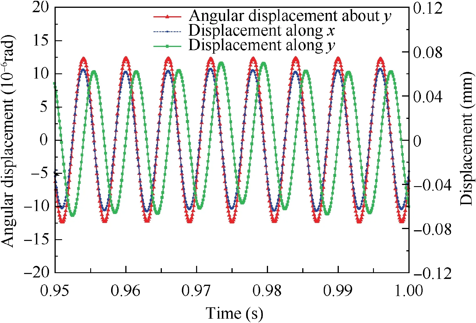
Fig. 14 Displacements of DOF γy4, x3 and y3.
A small segment in the stable stage of displacements of the γy4, x3and y3is extracted, as shown in Fig. 14. It is obvious enough that the swing vibration behavior of the driven gear shares the same feature with the transverse vibration of the turbine disk. The FFT is performed, as shown in Fig. 15. The vibration response of the driven gear will be significantly excited sharing the same frequency with HPR, which may cause HCF in the driven gear by swing vibration mode, especially near resonance frequencies.
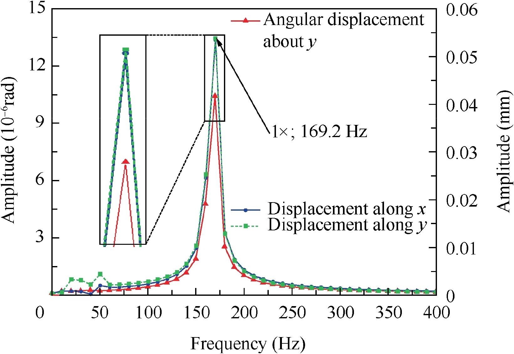
Fig. 15 Amplitudes of DOF γy4, x3 and y3.
4.5. Influences of factors on the unbalance response
If the vibration with swing mode of the driven gear can be significantly excited under unbalance forces on the HPR, it is of great significance to promote corresponding measures to suppress it.There are many measures,such as structural modification, passive vibration isolation, and active vibration control methods. Influences of parameters on the unbalance response were investigated for structural modification, such as the radius of the shaft where the driving gear is amounted,bearing stiffness, and meshing stiffness.
4.5.1. Radius of the shaft for fixing the driving gear
The radius of the shaft varied from 0.1 mm to 100 mm with the unbalance on HPR,and the vibration amplitude of the γy4was obtained,as shown in Fig.16.Two regions of changing rapidly are found,marked by A and B,and region A is magnified calculated from 9.0 mm to 10.0 mm.The curve appears to be continuous and first-order smooth within region A and B, and there are local minimum points marked by Aminand Bmin.For the reason of the local minimum and maximum points,it is relevant to the resonance frequencies and the antiresonance frequencies, which are varying with the structural modification, near the operation speed or far away from it.Take the point Amaxas an example to perform the calculation,and the corresponding radius is 9.455 mm; the results show that there exists a resonance frequency with 166.67 Hz, which is extremely close to the excitation frequency. The local minimum points represent ideal points to design or to solve the failure if the structural modification is achievable with an affordable cost.
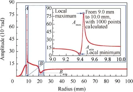
Fig. 16 Amplitude of γy4 varying with radius of shaft.
4.5.2. Bearing stiffness
In practice, to modify the radius of the shaft will take expensive costs, however, to change the bearing stiffness (representing the stiffness of support structure) is easy to realize. The stiffness of bearings varied from 106N/m to 108N/m for 1#,2# and 3# bearing, with only one of them changing for each calculation, and the vibration amplitude of γy4was obtained,as shown in Fig. 17. For each bearing, there are local maximum points(marked by letter H with numbers)and local minimum points (marked by letter L with numbers). Besides, the influences of each bearing are not sharing the same significance,and comparisons of influences on response are as shown in Table 4.
1) For each bearing, the difference between the minimum value and maximum value of response is rather large.Thus, each of them should be designed properly to suppress the unbalance response. If the design is good enough, the response can be suppressed extremely well.Otherwise, it may turn to be underlying damage.
2) It is more effective to change the stiffness of 1# and 2#bearing to suppress the vibration since 1# bearing and 2#bearing are of much greater significance than 3#bearing.However,the average value of response varying with 1#bearing was notably greater than the other two bearings,indicating that more attention shall be paid to it.
3) The amplitude varies rapidly in some regions, which means the response is extremely sensitive to the variation of the bearing stiffness.Thus,for better resistance to the inevitable variation of bearing stiffness in engineering,it is suggested to design the value within rather insensitive regions, which is called robust design method.28-30
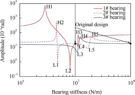
Fig. 17 Amplitude of DOF γy4 varying with bearing stiffness.

Table 4 Comparison of influence on response for different bearings.
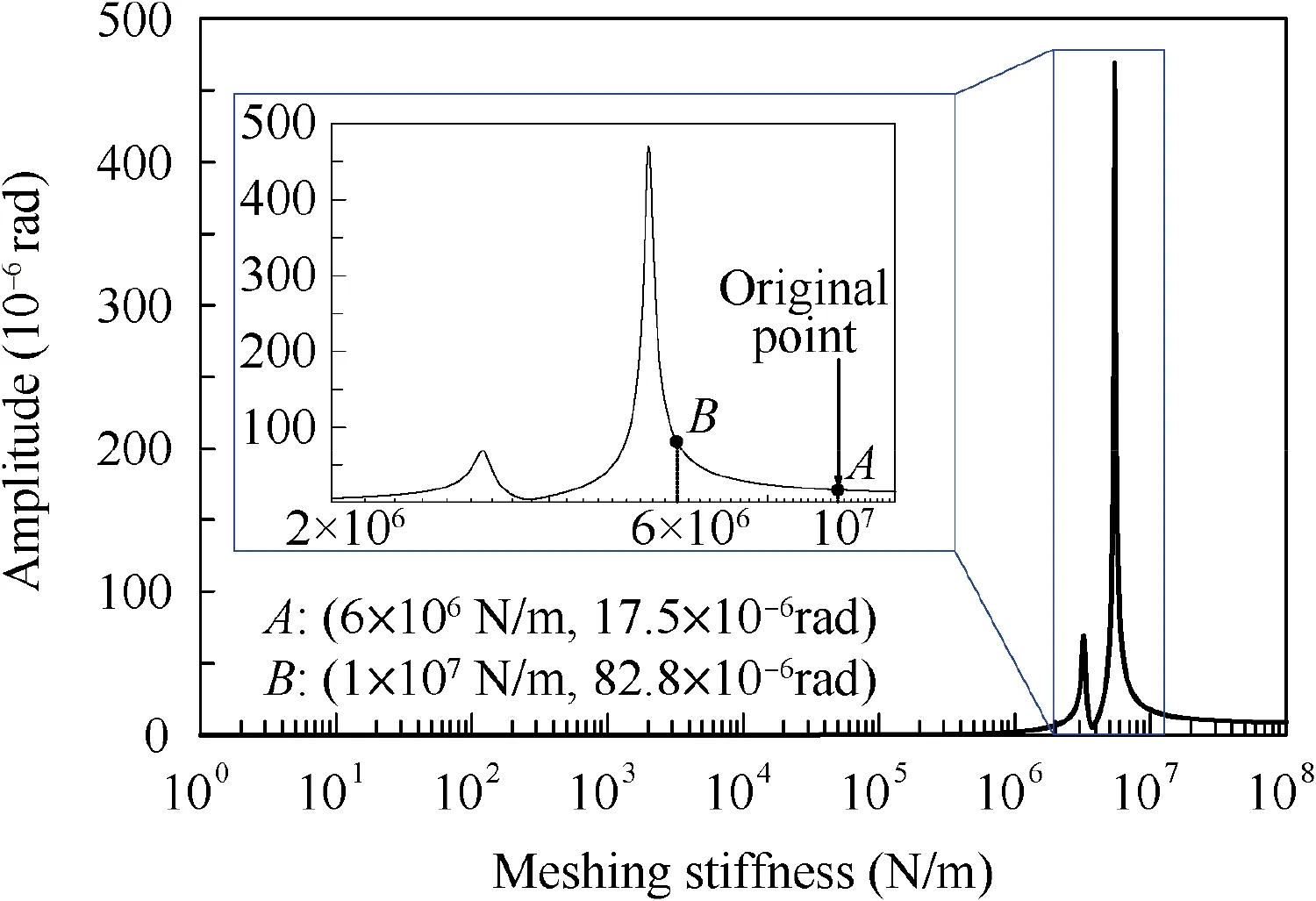
Fig. 18 Amplitude of γy4 varying with meshing stiffness.
4.5.3. Meshing stiffness
In above, the meshing stiffness was set a constant value 1×10⁷N/m, assuming that the intrinsic behavior of coupling vibration was not altered whatever the constant value was,as long as the system was described as a linear one. However,this value will change the natural frequencies and affect the energy transferred to the driven gear from HPR. The meshing stiffness varied from 1N/m to 1×10⁸N/m, and the response amplitude of γy4is as shown in Fig. 18.
The amplitude is almost zero with meshing stiffness under 1×10⁵N/m, indicating that the vibration of driven gear can’t be significantly excited by unbalance on the HPR with extremely weak meshing stiffness or unconsidered.When the meshing stiffness is not that weak, local maximum points can be found. Besides, the original meshing stiffness was set as the point of not the maximum ones,namely not a special value.If the meshing is varying from point A and point B,the response amplitude will be varying too.If the meshing stiffness is near to a peak point, it will be more dangerous for harmful vibration than the situation with the original meshing stiffness assumed before,which may more easily cause harm to the driven gear.
5. Conclusions
This paper aims at analyzing the fault with radial cracks in the driven gear disk of a certain type of aero-engines,and provides a significant reference for relevant study and application.Firstly, the fault analysis combining examinations, fault tree,and test signals indicated the underlying cause, and then, the corresponding mechanism model was established and analyzed to verify the underlying cause. Furthermore, the influences of factors have been studied to promote suggestions. Three main conclusions have been drawn, as following:
(1) According to the fault analysis combining examinations,fault tree, and test signals, the occurred fault in the specific aero-engines was diagnosed as the HCF failure of driven gear with features of two radial cracks, and the underlying cause was relevant to the swing vibration of the driven gear excited by the unbalance on HPR.
(2) Based on the corresponding mechanism model, modal shapes, harmonic response, and transient response,revealed that the swing vibration of driven gear can be significantly excited by unbalance force on HPR, which verified the underlying cause and was coinciding with the test signals.
(3) Furthermore, influences of factors have been studied,and the results shown that the unbalance response of driven gear could be controlled at a very low level,which can be applied to deal with the harmful vibration.Meanwhile, 1# and 2# bearing stiffness had rather significant influences on the response,so it is efficient and practicable to modify them for suppressing vibration.
Declaration of Competing Interest
The authors declare that they have no known competing financial interests or personal relationships that could have appeared to influence the work reported in this paper.
Acknowledgement
The authors would like to acknowledge the financial support from the National Natural Science Foundation of China(No. 51575022).
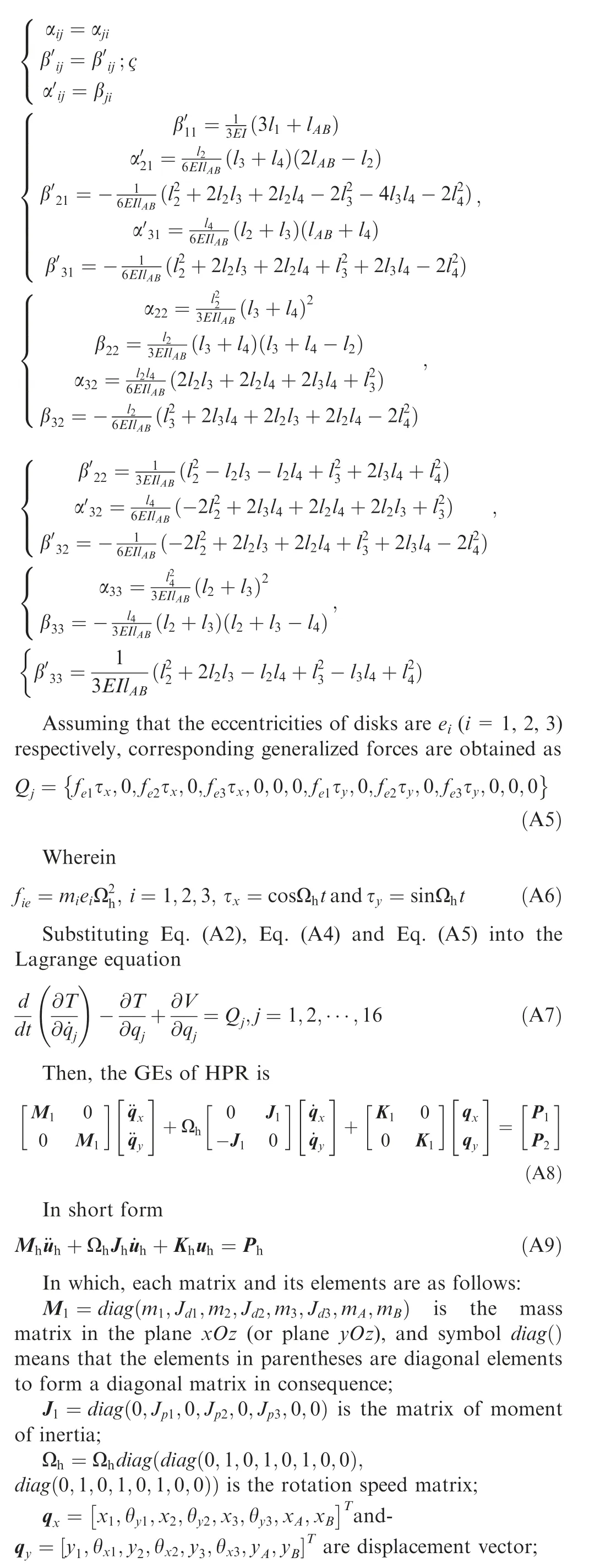
Appendix A. Deduction of GEs for HPR

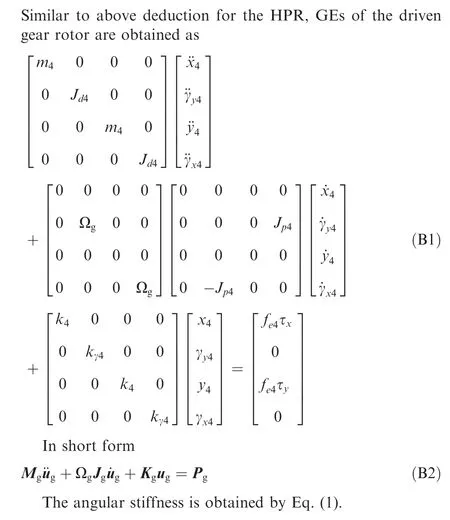
Appendix B. GEs of driven gear rotor
Appendix C. Specific parameters in Eq. (7)
Appendix D. Modal analysis method for GEs
For the Eq. (7), when the excitation forces are zeros, the solution results can be set to

 CHINESE JOURNAL OF AERONAUTICS2020年10期
- CHINESE JOURNAL OF AERONAUTICS的其它文章
- A novel surrogate modeling strategy of the mechanical properties of 3D braided composites
- A user-friendly yield criterion for metals exhibiting tension-compression asymmetry
- Aerodynamic characteristics of morphing wing with flexible leading-edge
- Motion equations of hemispherical resonator and analysis of frequency split caused by slight mass non-uniformity
- Light weight optimization of stratospheric airship envelope based on reliability analysis
- LPV modeling and controller design for body freedom flutter suppression subject to actuator saturation
