Aerodynamic characteristics of morphing wing with flexible leading-edge
Zi KAN, Daochun LI, Tong SHEN, Jinwu XIANG, Lu ZHANG
School of Aeronautic Science and Engineering, Beihang University, Beijing 100083, China
KEYWORDS Aerodynamics;Computational fluid dynamics;Flexible leading-edge;Morphing wings;Stall angle
Abstract The morphing wing can improve the flight performance during different phases. However, research has been subject to limitations in aerodynamic characteristics of the morphing wing with a flexible leading-edge.The computational fluid dynamic method and dynamic mesh were used to simulate the continuous morphing of the flexible leading-edge.After comparing the steady aerodynamic characteristics of morphing and conventional wings, this study examined the unsteady aerodynamic characteristics of morphing wings with upward and downward deflections of the leading-edge at different frequencies. The numerical results show that for the steady aerodynamic,the leading-edge deflection mainly affects the stall characteristic. The downward deflection of the leading-edge increases the stall angle of attack and nose-down pitching moment. The results are opposite for the upward deflection. For the unsteady aerodynamic, at a small angle of attack,the transient lift coefficient of the upward deflection, growing with the increase of deflection frequency, is larger than that of the static case. The transient lift coefficient of the downward deflection, decreasing with the increase of deflection frequency, is smaller than that of the static case.However, at a large angle of attack, an opposite effect of deflection frequency on the transient lift coefficient was demonstrated.The transient lift coefficient is larger than that of the static case when the leading edge is in the nose-up stage,and lower than that of the static one in the nose-down stage.
1. Introduction
With the development of the smart materials and intelligent controls structures, the morphing wing gets much attention recently. The aerodynamic shape of morphing wing can be optimized during different phases of flight, such as take-off,cruise and landing.In recent years,various concepts of morphing wing structures have been developed for better flight performance. The morphing wing structures, aerodynamics,aeroelasticity, control and optimization have also been studied.1,2Li et al.3summarized the most prominent examples of morphing concepts, and modelling and analysis methods of morphing wings.
Compared to the conventional high-lift configuration,such as leading-edge slats, the morphing wing with a flexible leading-edge, which is smooth and continuous without step or slot, is easier to manufacture and promises higher reliability.4,5Due to the advantages of the morphing leading-edge,several projects were initiated to research technologies suitable for the morphing wing. From 2008 to 2012, the Smart High Lift Devices for Next Generation Wings (SADE) project was carried out to investigate the design, manufacturing, and testing of a smart leading-edge device. Ground tests, low-speed wind tunnel tests and numerical simulation of a morphing leading-edge were conducted, indicating that the flexible leading-edge structures showed high shape accuracy and sufficient stiffness to overcome aerodynamic loads at different flight conditions.6-8From 2011 to 2014,supported by the project of Novel Air Vehicle Configurations: From Fluttering Wings to Morphing Flight (NOVEMOR), a morphing leading-edge model was designed and manufactured,9and then a wind tunnel test of droop-nose adaptive morphing wingtip was conducted. The results demonstrated adequate stiffness of the mechanism, and high suitability of the superelastic nickel titanium material for morphing applications.10In addition,funded by the Smart Intelligent Aircraft Structures(SARISTU) project, the integration of additional functionalities,such as de-icing,erosion protection and lightning strike protection, into a smart droop-nose device was investigated by simulations, ground tests11and low-speed wind tunnel tests.12Although the high-performance morphing wing with a flexible leading-edge has been designed, the mechanism needs to be further studied.
Aerodynamic analysis plays an important role in the process of translating morphing concepts into design. The Computational Fluid Dynamics (CFD) method is often used as a preliminary design tool to simulate aerodynamics, due to its high computational efficiency. Koreanschi et al.13used the two-dimension CFD method to study the airfoil with a morphing wing-tip,and the results were validated by the wind tunnel experimental date and numerical simulation results. A good agreement in the pressure distribution between the results of CFD and an experimental wind tunnel test for a morphing wing was demonstrated by Gabor et al.14.At present researchers often used the CFD method to study the morphing wing with flexible trailing-edge. Abdessemed et al.15used the CFD method to analyze the aerodynamic characteristics of the morphing wing which is based on NACA 0012 airfoil, results revealed that the local flow field is influenced by the morphing motion.Ai16and Jawahar17et al.used the RANS method with the Spallart-Allmaras turbulence model to numerically investigate the stall and aerodynamic performance of a NACA 0012 airfoil with flexible trailing-edge,and the Detached Eddy Simulations(DES)were also employed to investigate flow characteristics of the morphing wing.Lyu and Martins18adopted the Reynolds-Averaged Naiver-Stokes (RANS) equations with a Spalart-Allmaras turbulence model to study adaptive morphing trailing-edge wings, observing 1% drag reduction at ondesign conditions, and 5% drag reduction near off-design conditions.
Although plenty of research has been conducted in the field of morphing wings, there seems to need further studies about the aerodynamics of morphing wings with a flexible leadingedge. To address such a gap, the steady and unsteady aerodynamics of the morphing wing with a flexible leading-edge were examined by means of the CFD method.
The rest of this paper is organized as follows. The numerical methods and validation are presented in Section 2,and the steady and unsteady aerodynamic characteristics of a morphing wing with a flexible leading-edge are discussed in Section 3.Section 4 provides the conclusions of this study.
2. Numerical method and validation
2.1. Model and numerical method
2.1.1. Modeling method
The two-dimensional NACA 0012 airfoil with a flexible leading-edge was modeled for the numerical simulation.According to the concept mentioned in the literature,19the form of deformation is parabolic, and the deformable region is in the front quarter chord of the airfoil.A conventional rigid leading-edge and a flexible leading-edge are shown in Fig.1(a).The deflection angle of the leading edge γ is defined as the angle between the chord line and the line from the deflection axis to the leading edge, with the downward direction being the positive. The angle of attack α is defined as the angle between the chord line and the direction of free-steam velocity.
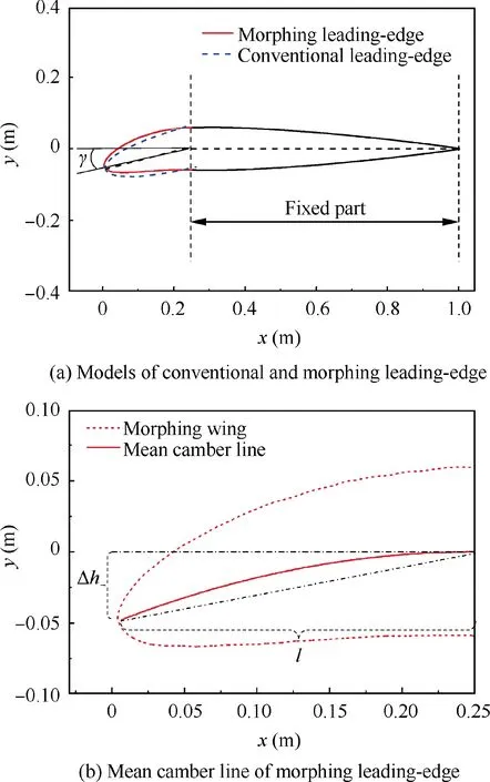
Fig. 1 Computational model of morphing wing.
Since the thickness of the morphing wing is constant, the model can be constructed as long as the trajectory equation of the mean camber line is known. As show in Fig. 1(b), the coordinate value of initial deflection point and the morphing leading-edge endpoint are (0.25, 0)and(0.25-l, -Δh), where l and Δh represent the horizontal and vertical distance from the leading-edge point to the deflection point, respectively. The mean camber line is in the form of y=a×(x-0:25)2, where a is an undetermined parameter. According to the geometric relationship, the deflection angle and the coordinate value of the leading-edge endpoint can be expressed as Δh ≈tanγ×0:25 cosγ, and l ≈cosγ×0:25. Then the trajectory equation of the mean camber line is

Then the dynamic mesh combined with User Defined Functions (UDFs) is adopted to achieve the continuous flexible morphing of the leading-edge. The position of grid nodes of the morphing wing is updated based on Eq. (1).
2.1.2. Numerical simulation method
The pressure-based Reynolds-Averaged Naiver-Stokes equation with the Spalart-Allmaras turbulence model was used to simulate the aerodynamic characteristics of morphing wings.A second order upwind scheme and central difference scheme were utilized for the convection terms and the diffusion terms,respectively. The boundary of computational domain was set as a pressure-far-field,and the airfoil was set as a no-slip static wall.Local cell remeshing method and spring-based smoothing method were adopted to update the mesh due to the large amplitude morphing of the leading-edge. As shown in Fig. 2,in order to be applicable to this method, the triangular cell types were adopted, and the grid was refined near the airfoil to improve the accuracy of the results.
In our research the dynamic mesh of local cell remeshing method combined with user defined functions was adopted to achieve continuous deflection of the leading-edge. For example, the deflection angle varies in the form of

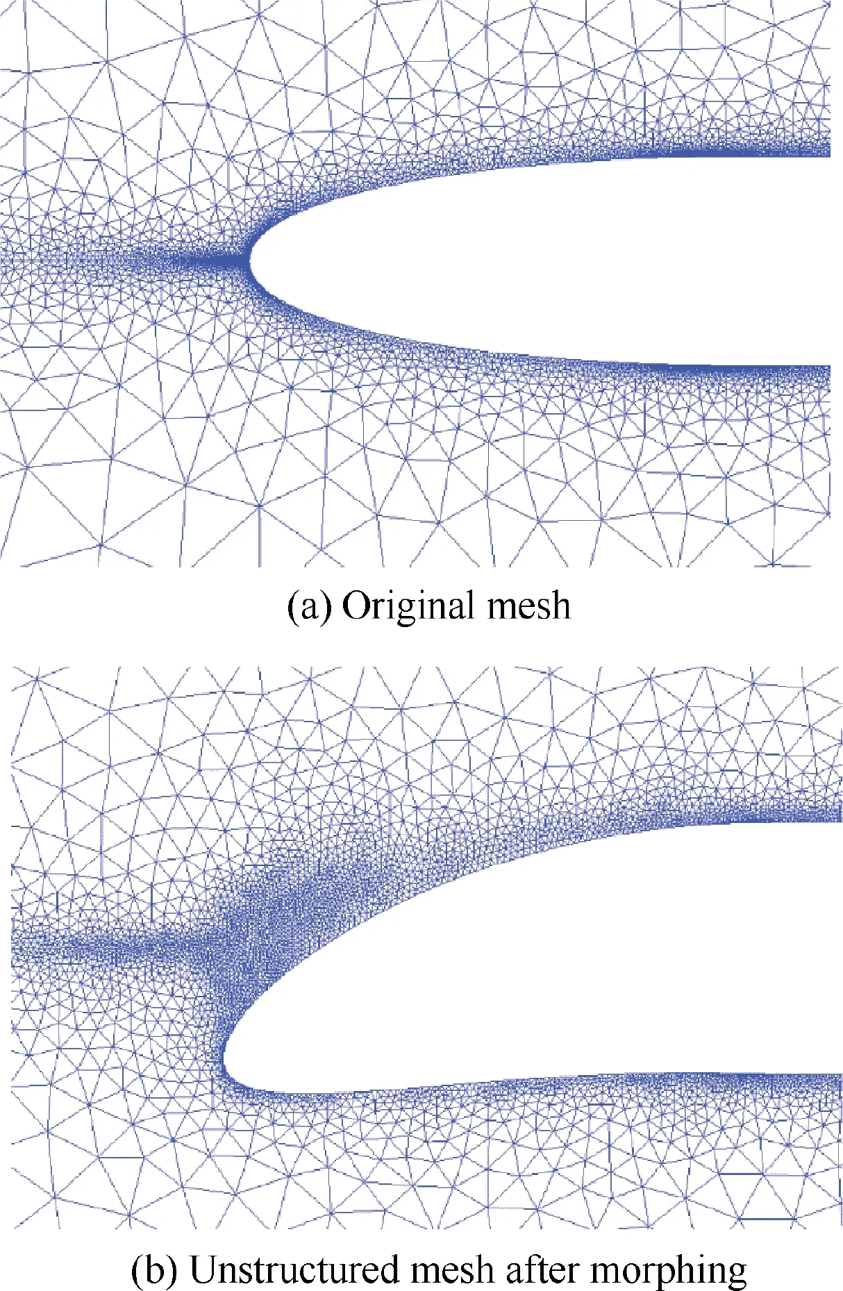
Fig. 2 Unstructured mesh layout of flexible leading-edge.
with f representing the deflection frequency(cycles per second),and γ0representing the maximum deflection angle of the leading-edge. In the deflection process, the region of 25%-100% chord of the airfoil is unchanged. The position of grid nodes of the morphing wing (x(t), y(t)) can be given by

In the morphing process, the location of each node on the boundary of the LE changes based on Eqs. (3) and (4), and the grids in the flow field reconstructs accordingly. Finally,the leading-edge can continuously deflect in the form of parabola. It should be noted that during the continuous deflection of the leading-edge, the Angle of Attack (AoA) remains unchanged.
2.2. Validation
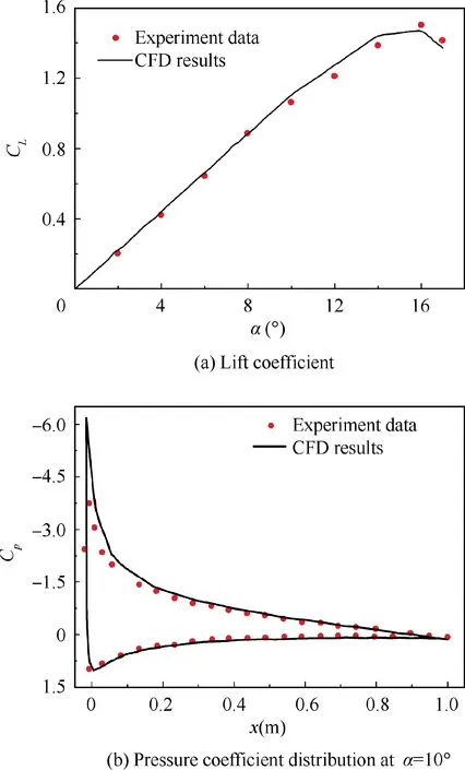
Fig. 3 Comparison between CFD results and experiment data under steady conditions.
To validate the accuracy of the numerical simulation,the CFD results in steady conditions were compared to the experimental results.20The Reynolds number (Re) was 6×10⁶, and the AoA(α) ranges from 0° to 17°. The comparisons of lift coefficient (CL) and of pressure coefficient (Cp) at α=10° between the CFD and experiment are shown in Fig.3(a)and Fig.3(b),respectively. As can been seen from the figures, the results of the numerical calculation were consistent with experimental result, in terms of both lift coefficients and pressure distribution. This means that the method adopted to simulate steady aerodynamic characteristics is sufficiently accurate.
To investigate the unsteady aerodynamic characteristics,the lift coefficients and moment coefficients (Cm) of the airfoil NACA 0012 obtained by CFD were compared with those of the experiment.21,22In unsteady conditions, the airfoil experienced the harmonic pitching motion about the quarter chord is

with the Mach number, Reynolds number, and frequency f being 0.302, 3.78×10⁶and 8.459 Hz, respectively. Fig. 4 shows the lift and moment coefficient curves. It can be seen that the lift coefficient obtained by CFD is similar to that of the experiment,especially during the increase of the stall angle of attack.However,the moment coefficients are slightly different, but their trends are consistent. Therefore, the numerical method used to simulate the unsteady lift coefficient is reliable.
3. Results and discussions
3.1. The steady aerodynamic characteristics of leading-edge deflection
3.1.1. Comparison of the morphing and conventional wings
The aerodynamic characteristics of the morphing wing and the conventional wing were studied numerically. The Mach number and Reynolds number of the flow were 0.2 and 4.6×10⁶, respectively, and the deflection angle γ was 16°.
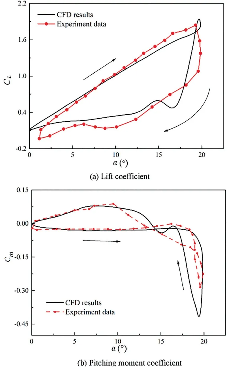
Fig. 4 Comparison between CFD results, experiment data and extended-ONERA method under unsteady conditions.
Fig. 5(a) shows the lift coefficient curves of the conventional and morphing wings. It can be seen that the slope of the lift curve of the morphing wing is nearly identical with that of the conventional wing,and the morphing wing has a higher lift coefficient than the conventional one, especially near critical stall angle. Further, the stall angle of attack and the maximum lift coefficient of the morphing wing are larger than those of the conventional wing. The maximum lift coefficient of the morphing wing is about 8%larger than that of the conventional wing.
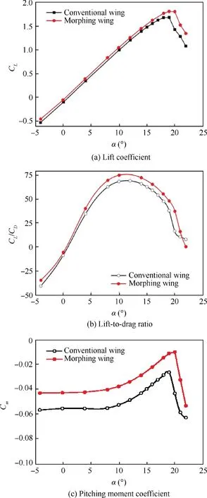
Fig. 5 Aerodynamic coefficients of conventional and morphing wings.
Fig. 5(b) shows the lift-to-drag ratio (CL/CD) characteristics. The lift-to-drag ratio of the two wings initially increase to the maximum, and then decrease as the angle of attack increases.The morphing wing is clearly superior to the conventional wing in terms of the lift-to-drag ratio. The morphing wing achieves a maximum lift-to-drag ratio, 75.2 at α=10°,which is 10.3% larger than that of the conventional wing,68.2 at α=12°. Additionally, as seen in Fig. 5(c), the curves of the moment coefficient about the quarter chord show that the morphing wing has a lower nose-down pitching moment coefficient than the conventional wing, improving control surface efficiency and aerodynamic performance.
To explain the differences of the aerodynamic coefficients,the flow fields and the pressure distributions of the morphing and conventional wing at α=20°were extracted.Fig.6 shows that the pressure coefficient on the upper surface of the conventional wing has a sudden change around the deflection position of the rigid leading-edge,while the pressure coefficient of the morphing wing changes gradually. As a result, the area enclosed by the pressure coefficient curves of the morphing wing is larger than that of the conventional one, leading to a higher lift coefficient. Fig. 7 shows that a large vortex appearing from the rotation position attaches to the trailing-edge of the conventional wing,but the morphing wing has only a small vortex in the rear area.Due to a great change in the curvature of the leading-edge surface of the conventional wing, the flow separation occurs earlier and more violently, while the continuous morphing of the leading-edge can help reduce the negative pressure gradient, attaching the flow to the surface of the wing.This indicates that the morphing wing with a flexible leading-edge has a better aerodynamic performance than the conventional one.
3.1.2. The effect of the deflection angle on steady aerodynamics
Fig. 8 shows the aerodynamic coefficients with the leadingedge deflection angles of 0°, -4°, 4° and 12°. As shown in Fig.8(a),the leading-edge deflection mainly affects stall angle.The upward deflection of the leading-edge decreases the stall angle of attack, leading to the reduction of the maximum lift coefficient. Conversely, the maximum lift coefficient and stall angle of attack are significantly increased by the downward deflection of the leading-edge. In Fig. 8(b), it can be seen that the leading-edge upward deflection causes a slight nose-up pitching moment about the quarter-chord. However, the downward deflection results in a higher nose-down pitching moment coefficient, and the larger the deflection angle is, the higher the coefficients of lift and nose-down pitching moment will become. Fig. 8(c) shows that when the angle of attack comes to 10°, the maximum lift-to-drag ratio occurs, and in comparison with the baseline airfoil (γ=0°), the maximum lift-to-drag ratio of the morphing wing with γ=4° and γ=12°, increase by 1.6% and 10.1% respectively. Apparently, the downward deflection is conducive to improve the lift-to-drag ratio characteristics, while the upward deflection has the opposite effect.
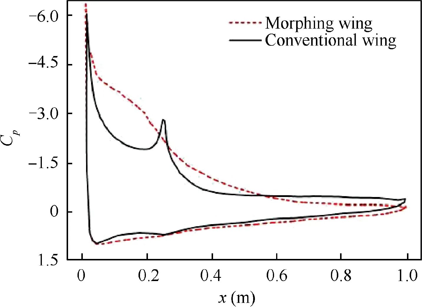
Fig. 6 Pressure coefficient distributions of conventional and morphing wings at α=20°.
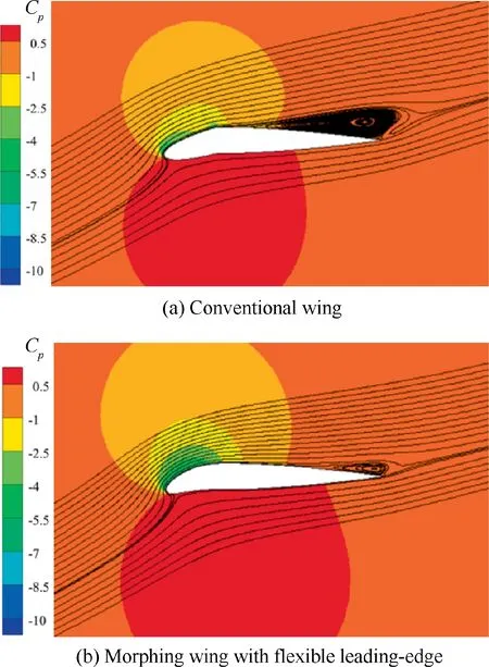
Fig. 7 Pressure and flow fields of conventional and morphing wings at α=20°.
Fig. 9 is the pressure distribution of the morphing wing with different leading-edge deflection angles at α=16°. Pressure distributions on the lower surface are nearly the same,while the pressures on the upper surface reveal obvious differences. Compared to the baseline airfoil (γ=0°), the area enclosed by pressure coefficient curves becomes larger with the downward deflection. However, the upward deflection shows completely different effects, leading to a reduction of the lift coefficient.
Fig. 10 shows the pressure and flow fields of the morphing wing with different leading-edge deflection angles. When the leading-edge deflects downward, the negative pressure area is larger than the baseline airfoil(γ=0°),thus increasing the lift.In addition, more flow is attached on the wing surface, delaying the flow separation. On the contrary, when the leadingedge deflects upward, the negative pressure area decreases and the flow separates obviously near the trailing edge, therefore decreasing the lift.
3.2. The unsteady aerodynamic characteristics of leading-edge deflection
In this section,the unsteady aerodynamic characteristics of the flexible leading-edge during the periodic deflection is analyzed.The leading-edge deflection angle varies in the form of
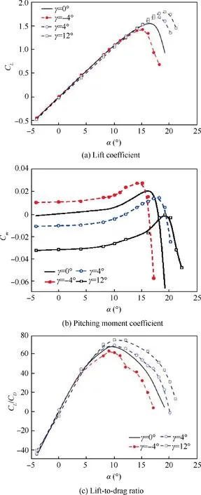
Fig.8 Aerodynamic coefficients of morphing wing with different leading-edge deflection angles.

The influence of the leading-edge deflection frequency on the unsteady aerodynamic coefficient at a small angle of attack(α=4°) and a large angle of attack (α=16°) is discussed.
3.2.1. Small angle of attack
Fig. 11 shows the static and transient lift coefficients of the morphing wing when the leading-edge deflects at α=4°. The static case means that the leading-edge fixes at a certain deflection angle, while the dynamic case means that the flexible leading-edge is undergoing periodic deflection with different frequencies. It can be seen that at a small angle of attack,the change of the lift coefficient is extremely small at 10-2order of magnitude.
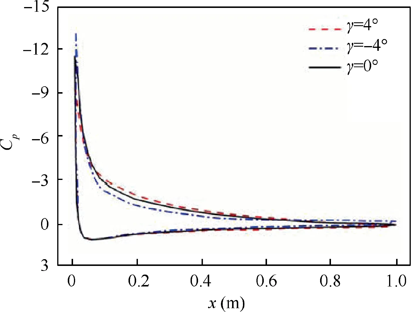
Fig. 9 Pressure coefficient with different leading-edge deflection angles at α=16°.
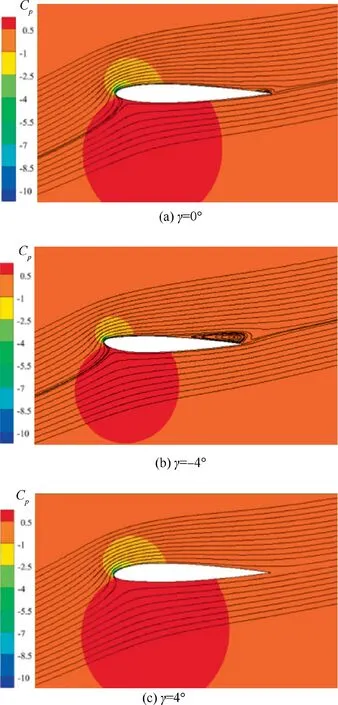
Fig. 10 Pressure and flow fields with different leading-edge deflection angles at α=16°.
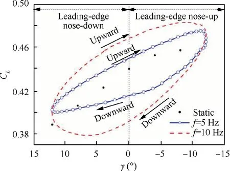
Fig. 11 Static and transient lift coefficients of leading-edge deflection at α=4°.
For the static case, the steady lift coefficient increases with the increase of the upward deflection angle,which is consistent with the results in Fig.8(a).For the dynamic case,the lift coefficients in the process of upward and downward deflection demonstrate completely different characteristics. In the upward deflection,the transient lift coefficient is always higher than that of the static one, and the larger the deflection frequency is, the higher the transient lift coefficient will be. For example, at γ=0°, the lift coefficients increase by 2.2% and 6.4% with f=5 Hz and 10 Hz, respectively. On the contrary,in the process of downward deflection,the transient lift coefficient is always lower than that of the static one,and the larger the deflection frequency is, the lower the transient lift coefficient will be. For example, at γ=0°the lift coefficients decrease by 5.6% and 10.9% with f=5 Hz and 10 Hz,respectively.
In addition, the lift coefficient changing with the deflection angle presents a hysteresis loop which moves in a clockwise direction, and the smaller the deflection frequency, the more sharply the hysteresis loop slopes. Further, no matter whether the leading-edge is in the nose-down stage or the nose-up stage,the lift coefficient is higher than that of the static one during the upward deflection, but lower during the downward deflection.
Fig. 12 presents the pressure coefficients of the morphing wing when the leading-edge deflects passing γ=0° with f=10 Hz at α=4°. When the leading-edge passes γ=0°during the downward deflection, as shown by the blue line,the suction peak of the upper surface is the highest.The reason may be that the downward trend of the leading-edge delays the flow attached to the upper surface,leading to a larger negative pressure area. Similarly, when the leading-edge deflects upward, the upward trend is transmitted to the flow nearby,increasing the pressure on the lower surface and decreasing the pressure on the upper surface. Thus, when the flexible leading-edge deflects upward at a small angle of attack,the lift coefficient is higher than that of the static case.
3.2.2. Large angle of attack
Fig. 13 shows the static and transient lift coefficients of the leading-edge deflection with f=5 Hz and f=10 Hz at α=16°. The trend of these coefficients is different from that under a small angle of attack. The relationship between static and transient lift coefficients is more complicated and the influence of deflection frequency on transient lift coefficients is also different, so we divided the whole process into upwards and downwards deflection phases to analyze the unsteady aerodynamic characteristics of the morphing wing.
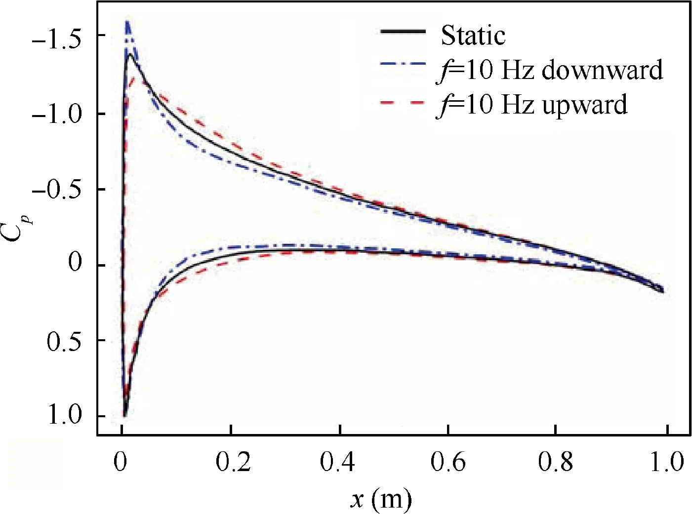
Fig. 12 Pressure coefficients of static and dynamic cases at α=4°, γ=0°.
First, consider the upward deflection process. As shown in Fig.13(a),the transient lift coefficient is lower than that of the static one when the leading-edge is at nose-down stage. With the leading-edge deflecting upward,the transient lift coefficient begins to increase.On the contrary,the transient lift coefficient becomes higher than that of the static one in the nose-up stage.In the upward deflection process, the larger the deflection frequency is, the lower the transient lift coefficient will be.
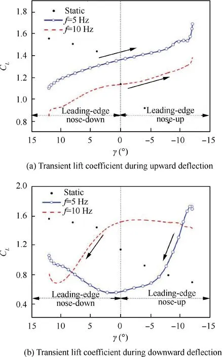
Fig. 13 Transient lift coefficients under different deflection phases at α=16°.
Then, the aerodynamic characteristics of the morphing wing in the downward deflection process is analyzed. As shown in Fig. 13(b), the characteristics in the down ward deflection are similar to those in the upward deflection. The transient lift coefficient of the leading edge is smaller than that of the static one at the nose-down stage,but larger at the noseup stage. However, different from the upward deflection, the downward one(about from γ=-10°or γ=8.5°)reveals that the larger the deflection frequency is, the higher the transient lift coefficient becomes.
To investigate the factors to cause the complex change of the lift coefficients, two positions of the flexible leading-edge deflection as typical deflection positions were selected. One position is downward passing γ=0°,and the other is upward to γ=-12°.Figs.14 and 15 display the pressure distributions and flow fields of the morphing wing with the two typical deflection locations at α=16°.
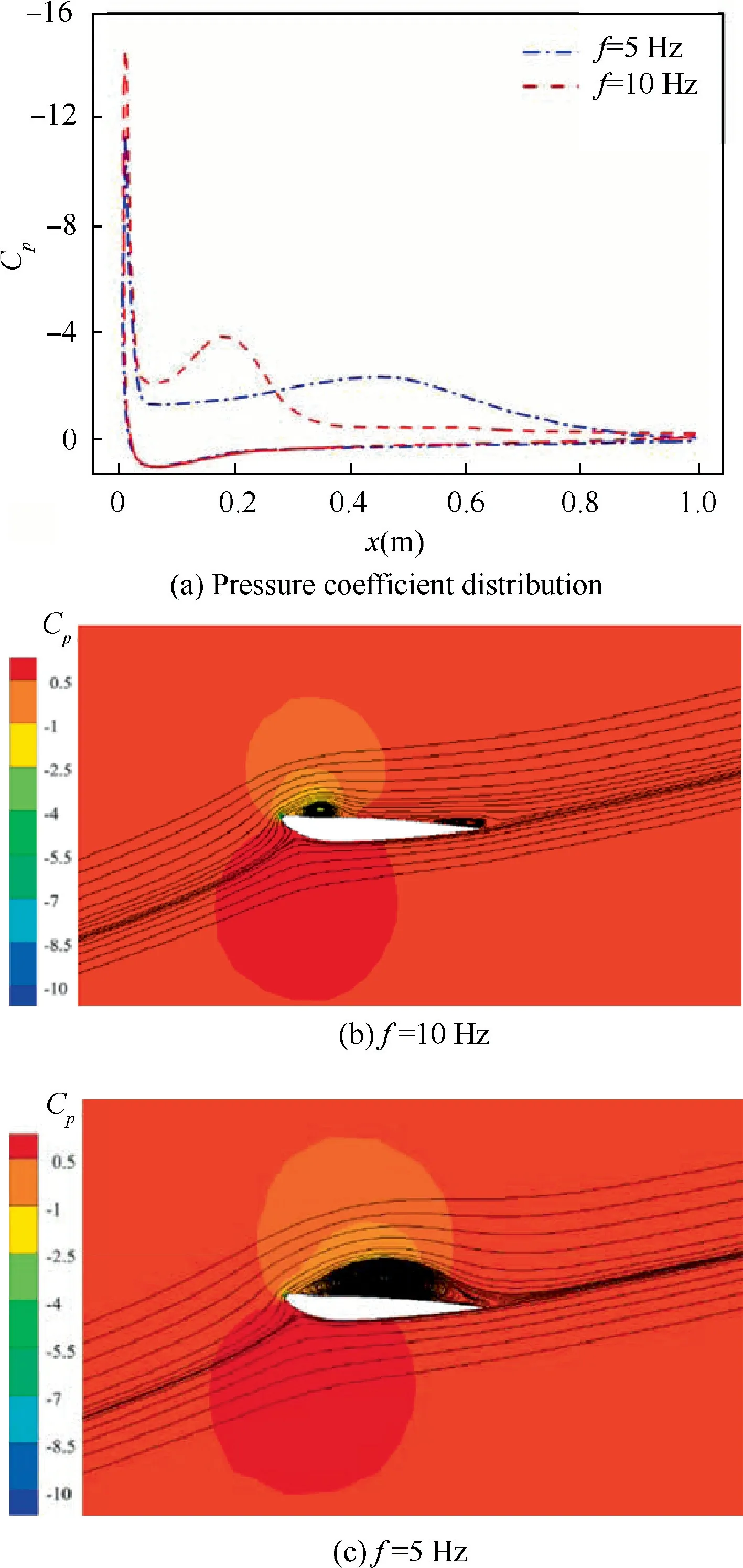
Fig.14 Pressure and flow fields of static and dynamic cases with different frequencies: upward deflection, γ=-12°, α=16°.
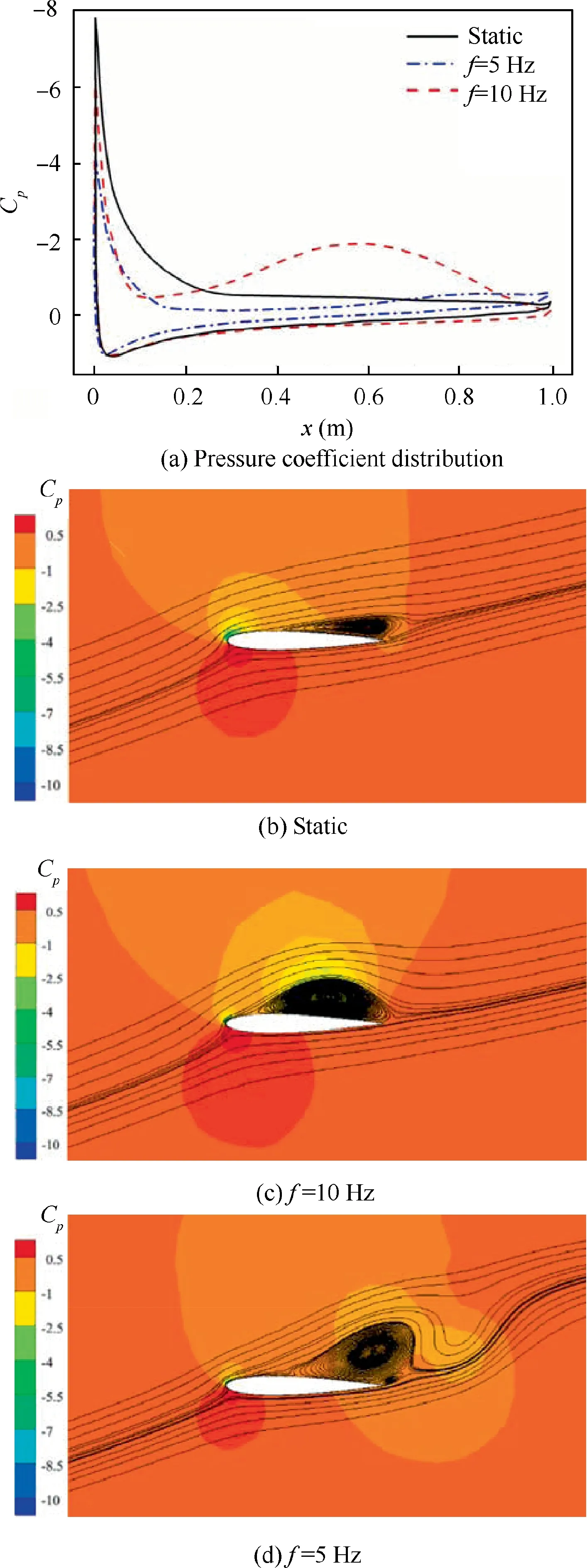
Fig.15 Pressure and flow fields of static and dynamic cases with different frequencies: downward deflection, γ=0°, α=16°.
Fig.14 analyzes the pressure distributions and flow fields of the flexible leading-edge when it deflects upward to γ=-12°with f=5 Hz and f=10 Hz. In the upward deflection process, the flow separates from the leading edge and extends downstream. Fig. 14(b) shows that when the flexible leadingedge reaches to γ=-12° with f=10 Hz, the separation vortex is located on the upper surface and has not extended downstream, which also can be seen in Fig. 14(a). However, when the flexible leading-edge deflects with f=5Hz, the complete separation zone has formed on the upper surface at γ=-12°,as shown in Fig.14(c),so the area of negative pressure and the lift coefficient with f=10 Hz are smaller than those with f=5 Hz.
As shown in Fig. 15(a), when the leading-edge deflects downward passing γ=0° with f=10 Hz, the pressure distribution on the upper surface shows a larger area of negative pressure than that of the static case and the dynamic case with f=5 Hz,so the lift is the largest.For the static case,flow separation occurs at the position of half chord length and the separation area is small. In the downward deflection process,when the flexible leading-edge deflects from γ=-12° with f=10 Hz,the separation vortex begins to extend downstream,and a complete separation zone occurs on the upper surface until the leading-edge goes through the position of γ=0°, as shown in Fig. 15(c). So the lift coefficient decreases after this moment. However, when the leading-edge deflects downward with f=5 Hz, the separation vortices extends downstream and falls off at the trailing-edge points at this typical deflection position, thus reducing the lift coefficient. Compare Fig. 14(c)with Fig. 15(c), it is found that the position and range of separation vortex are similar, which means that the separation vortex shedding is delayed with the increase of the deflection frequency.
The analysis above provides insight into manipulating leading-edge deflection. For example, the leading-edge should deflect downward as slowly as possible, and upward as quickly as possible at a small angle of attack to improve unsteady aerodynamic performance of the wings. However,at a large angle of attack, the leading-edge should deflect upward as slowly as possible, and downward as quickly as possible.
4. Conclusions
In our research, the steady aerodynamic characteristics of morphing and conventional wings were compared, and the steady and unsteady aerodynamic characteristics of the morphing wing with a flexible leading-edge were analyzed.The influence of two parameters, deflection frequency and deflection angle, on the unsteady lift coefficient was discussed.
(1) The morphing wing has higher lift coefficient,higher liftto-drag ratio, and smaller nose-down pitching moment coefficient than the conventional wing before the occurrence of stall when the flexible leading-edge deflects downward.
(2) For the steady aerodynamic characteristic,the deflection of the flexible leading-edge has little effect on the aerodynamics at a small angle of attack. The leading-edge deflection mainly affects the stall characteristic. The downward deflection of the leading-edge increases the stall angle of attack and nose-down pitching moment.Further, the larger the downward deflection angle, the better the lift-to-drag characteristic of the morphing wing at a small angle of attack will be. The results are opposite for the upward deflection.
(3) For the unsteady aerodynamic characteristic at a small angle of attack, in the upward deflection process of the flexible leading-edge, the transient lift coefficient is higher than that of the static case, and the higher the deflection frequency is, the larger the transient lift coefficient will be. However, when the leading-edge deflects downward, the transient lift coefficient is smaller than that of the static case, and the higher the deflection frequency is,the smaller the transient lift coefficient will be.
(4) For the unsteady aerodynamic characteristic at a large angle of attack, in the deflection process, the transient lift coefficient is larger than that of the static case when the leading-edge is in nose-up stage. However, in the nose-down stage, the transient lift coefficient is lower than that of the static one, and the effect of deflection frequency is opposite to that at a small angle of attack.
Acknowledgement
This study was supported by the Beijing Advanced Discipline Center for Unmanned Aircraft System.
 CHINESE JOURNAL OF AERONAUTICS2020年10期
- CHINESE JOURNAL OF AERONAUTICS的其它文章
- A novel surrogate modeling strategy of the mechanical properties of 3D braided composites
- A user-friendly yield criterion for metals exhibiting tension-compression asymmetry
- High cycle fatigue failure with radial cracks in gears of aero-engines
- Motion equations of hemispherical resonator and analysis of frequency split caused by slight mass non-uniformity
- Light weight optimization of stratospheric airship envelope based on reliability analysis
- LPV modeling and controller design for body freedom flutter suppression subject to actuator saturation
