Experimental and numerical investigation on surface quality for two-point incremental sheet forming with interpolator
Xioqing LI, Ki HAN, Xu SONG, Hio WANG, Dongsheng LI,Ynle LI, Qing LI
a School of Mechanical Engineering and Automation, Beihang University, Beijing 100083, China
b School of Mechanical and Materials Engineering, North China University of Technology, Beijing 100144, China
c Key Laboratory of High Efficiency and Clean Mechanical Manufacture, Ministry of Education, School of Mechanical Engineering, Shandong University, Jinan 250061, China
d Materials Science Branch of Chinalco Research Institute, Chinalco Materials Application Research Institute Co.,LTD,Beijing 102209, China
KEYWORDS Forming force;Geometric error;Interpolator;Process parameter;Surface quality;Two-point incremental sheet forming
Abstract The unsatisfied surface quality seriously impedes the wide application of incremental sheet forming(ISF)in industrial field.As a novel approach,the interpolator method is a promising strategy to enhance the surface quality in ISF. However, the mechanism for the improvement of surface quality and the influence of interpolator properties on surface roughness are not well understood.In this paper,the influences of process variables(i.e.tool diameter,step size and thickness of interpolators) on the forming process (e.g. surface roughness, forming force and geometric error)are investigated through a systematic experimental approach of central composite design (CCD)in two-point incremental sheet forming(TPIF).It is obtained that the increase in thickness of interpolators decreases the surface roughness in direction vertical to the tool path while increases the surface roughness in direction horizontal to the tool path. Nevertheless, the combined influence between thickness of interpolators and process parameters (tool diameter and step size) is limited.Meanwhile,the placement of interpolator has little influence on the effective forming force of blank.In addition,the geometric error enlarges with the increase of step size and thickness of interpolator while decreases firstly and then increase with an increase in tool diameter. Finally, the influencing mechanism of the interpolator method on surface quality can be attributed to the decrease of the contact pressure due to the increase of contact area with the unchanged contact force. Meanwhile,the interpolator method eliminates the sliding friction on the surface of blank due to the stable relative position between the blank and the interpolator.
1. Introduction
Incremental sheet forming (ISF) receives widespread study with its advantages of economy and flexibility in small batch sheet metal parts.1-5ISF can be classified into single-point incremental sheet forming (SPIF) without dies and two-point incremental sheet forming(TPIF)with a die,1where TPIF normally shows better formability and geometric accuracy than SPIF.6In ISF, a local loading is imposed on the sheet by directly contacting with the forming tool so that the localized material deformation is produced.As the forming tool moving along the designed tool path, the desired shape can be formed by the accumulation of these localized deformations.1However, the local loading also causes surface quality problems of the formed part,such as the waved impression and the friction trace,which seriously impedes the wide application of ISF in industrial field.
The influence of process parameters on the surface quality was investigated substantially. Hagan and Jeswiet7investigated the surface roughness of AA3003 in SPIF using different step sizes and spindle speeds. They found that the decrease of step size significantly decreases the surface roughness while the spindle speed has a very limited effect on it.Powers et al.8investigated the influence of the feed rate and rolling direction of material on surface roughness through a slot forming experiment in SPIF. It was found that the influence of feed rate is not notable and the roughness is worse in the case that the forming direction is vertical to the rolling direction. Bhattacharya et al.9experimentally studied the influence of process parameters on the formability and the surface roughness in SPIF. It was concluded that the surface roughness decreases with the increase of both tool diameter and forming angle while increases with the increase of step size. To improve the surface roughness of the part with various forming angle, Attanasio et al.10designed a tool path with various step sizes according to the desired imposed height between the tool shapes at two adjacent steps. Then, Durante et al.11proposed an analytical model to predict the surface roughness with different tool diameters and step sizes based on the desired imposed height.Liu et al.12established the relationship between the surface roughness and process parameters through a systematic experimental approach. It was shown that the sheet thickness and step size are two most effective factors on surface roughness, followed by the tool diameter and feed rate. Meanwhile, Wei et al.13found that the surface roughness increases with the increase in the thickness and the decrease in the mean flow stress in SPIF. Kurra et al.14conducted a multi-objective optimization considering the surface roughness and processing time. They found that the type of lubricant and feed rate show little influence on surface roughness.Jawale et al.15investigated the microstructural influence of lubrications on the surface roughness. It was claimed that the types of lubrication have little effect on the grain size or grain shape while the mineral oil shows better performance in terms of surface roughness compared with the paste-state lubrication. In summary, tool diameter and step size have significant influence on the surface roughness while the type of lubricant, spindle speed and feed rate only show limited effect. Nevertheless, the waved impression and friction trace left on the formed part surface can not be completely eliminated by merely adjusting process parameters.
To further improve the surface quality,some novel forming tools and methods have been proposed. Ajay and Vishal16investigated the influence of different tool shape on surface roughness and found the surface quality of parts formed with hemispherical tool shape is better than that with other shapes.Kim and Park17suggested that a rolling tool with a free rotating ball at the end shows better performance on the surface quality compared with the conventional forming tool with a hemispherical head. However, the maximum forming angle of the rolling tool is limited due to the interference between the part and rolling tool.Later,to overcome the forming limit,Lu et al.18designed a rotating tool whose rotating ball end was assembled by the side of tool.During the forming process,the rotation angle of forming tool needs to be controlled carefully to make the ball end keep contacting with the sheet. They found that the rotating tool could not only decrease the surface roughness but also reduce the shear deformation in the circumferential direction caused by the friction. Differently, Him et al.19developed a forming tool made by acetal which was effective to reduce the waved impression, but the surface roughness was increased due to the lack of burnishing efficacy of the forming tool made by carbide. Meanwhile, a novel forming approach, namely the interpolator method, is proposed by Skjoedt et al.20and Alves et al.21. They investigated the influence of the interpolator on the formability and surface roughness in SPIF. It was found that this method effectively reduces the waviness on the part surface in SPIF.However,little investigation has been performed regarding the influence of the interpolator properties and the combined influence between the interpolator and process parameters on surface quality. Meanwhile, the mechanism for improving surface quality by interpolator method has not been well understood and this method has not been used for TPIF.
Since the finite element simulation for ISF is still timeconsuming, experimental investigation remains an efficient and precise approach for ISF research.Therefore,the influence of the interpolator properties (e.g. interpolator thickness) and combined influence between process parameters on surface quality will be studied through a systematic experimental approach. Meanwhile, the influence of process parameters on forming force and geometric error are also analyzed. Finally,the mechanism for improving surface quality by interpolator method is discussed. The main contributions of this work to the field are:
· The interpolator method effectively decreases the surface roughness in the vertical direction which is the major surface problem of the formed part by TPIF.
· The effective forming force remains the same level after adopting the interpolator method.
· The mechanism for the improvement of the surface quality by the interpolator method is attributed to the decrease of the contact pressure and increase of the contact area.
2. Methodologies
2.1. Interpolator method
For traditional TPIF processes, the blank is clamped on the blankholder and deformed by the pressing of the forming tool and the supporting of the die,as described in Fig.1(a).As the forming tool moving along the tool path, both the waved impression caused by the local contact pressing and the friction trace caused by the sliding friction are left on the surface of blank.As shown in Fig.1(b),the waved impression roughness is the major surface quality problem of ISF since the roughness value of waved impression is larger compared with friction trace.12
In the interpolator method,an interpolator is placed on the top surface of blank and then the interpolator and the blank are clamped together by a blankholder as described in Fig. 1(c). During the forming process, the interpolator is directly contacted with the forming tool while the blank is formed by the pressing of the interpolator and the supporting of the die. As the forming tool moving along the designed tool path,the interpolator and blank are deformed into target shapes simultaneously during which the relative position between interpolator and blank is stable.
As shown in Fig. 2, the arithmetic mean surface roughness(Ra) and maximum peak to valley height (Rz) of the parts formed with different thickness of interpolator are compared.It is shown that the roughness values of specimens formed without an interpolator, namely the thickness of interpolator of 0 mm, are more than those formed with interpolators of 0.5 mm and 1.0 mm, indicating that the interpolator method is effective to improve the surface quality. In addition, the roughness of specimen is affected by the variation of thickness of interpolator and step size.Therefore,the influence of thickness of interpolator on surface roughness will be further investigated.
2.2. Experimental design and setup
The influences of three variables including interpolator thickness, tool diameter and step size on the surface quality, forming force and geometric error are investigated. Specifically, a central composite design(CCD)is adopted to evaluate the corresponding importance of each variable. Three levels of each variable are selected as listed in Table 1 and the experimental matrix for the CCD is obtained through the Minitab software,as presented in Table 2.
In this study, a shallow dome specimen (Fig. 3 (a)) is selected as the target shape which normally presents poor surface quality by ISF.The blank material is AA2024-O which is widely used for aircraft skins, and is cut into a dimension of 500 mm×400 mm×1.5 mm for the forming process. The material for interpolator is steel DC04 which is cheap and widely used in deep drawing featured with high formability.The chemical composition of the aluminum sheet is listed in Table 3.In the forming process,the specimens are formed with a feed rate of 5000 mm/min and the lubricant is smeared on the surface of the blank and interpolator. All specimens are formed on a dedicated incremental forming machine as shown in Fig. 3 (b).
2.3. Measurement
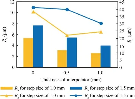
Fig.2 Surface roughness for different thicknesses of interpolator and step sizes.

Table 1 Variables and their levels.
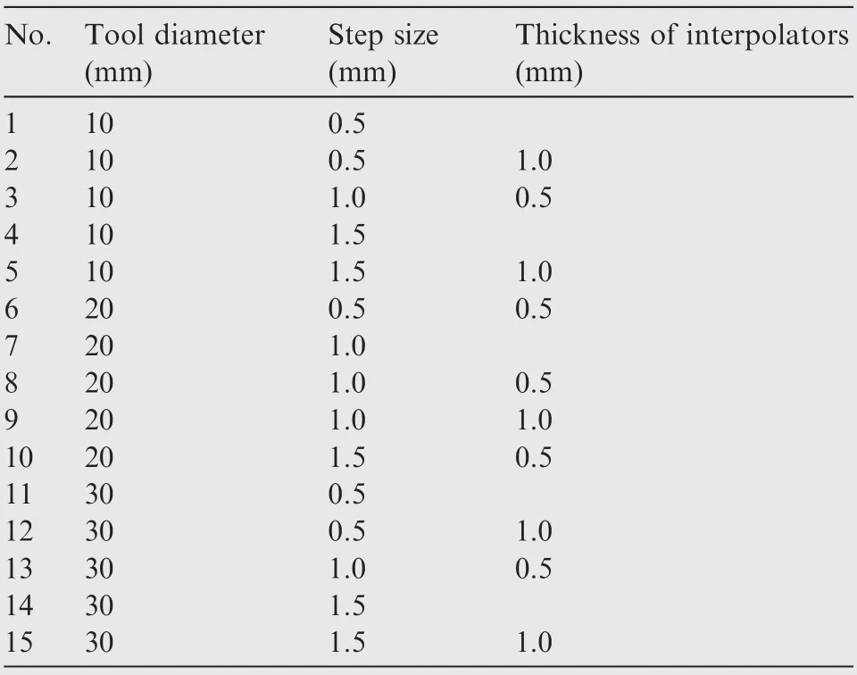
Table 2 Central composite design.
In this work, the surface roughness, geometric profile and forming force for all specimens are evaluated.Since the waved impression is the major issue for surface quality of ISF, the surface roughness in the direction vertical to the tool path(VD) is measured to evaluate the waved impression. Meanwhile,the surface roughness in direction horizontal to the tool path(HD)is also measured.As shown in Fig.4(a)and(b),the surface roughness along VD and HD are measured at region P and region H (Fig. 3 (a)) respectively using a roughness tester considering the structure limit of the specimen. Meanwhile,both Raand Rzare obtained for the roughness evaluation.During the forming process,the forming force is recorded with a three-axis force sensor (FC3D160) shown in Fig. 3 (b). In addition, geometric profiles of specimens are measured with a three-coordinates measuring machine (CMM).
2.4. Finite element model
A simplified model is developed with ABAQUS/Explicit 6.14 to explain the improvement of the surface quality by using an interpolator. As shown in Fig. 5, the interpolator is placed on the blank with a size of 40 mm×30 mm×1.5 mm and the boundaries of blank and interpolator are fixed. In the simplified forming process,the forming tool firstly moves down with a step size of 1.0 mm along the Z-axis direction, and then moves along the X-axis direction with a distance of 20 mm and a feed rate of 6000 mm/min. Interpolators with three different thicknesses (0 mm, 0.5 mm and 1.0 mm) are used to compare the interpolator method with the traditional method and to investigate the influence of thickness on the contact condition (contact area and contact normal stress).
The interpolator and the blank are defined as DC04 and AA2024 and the mechanical properties are listed in Table 4.The true stress-strain curves of the materials in the rolling direction are depicted in Fig. 6 and are represented with the isotropic hardening model. In the FE model, the blank (with 14400 elements) and interpolators (with 4800 elements) are meshed with solid elements C3D8R with a size of 0.5 mm×0.5 mm×0.5 mm while the forming tool is defined as analytical rigid with a diameter of 30 mm.Meanwhile,the friction coefficient is defined as 0.1 and the contact mode is defined as penalty contact method. In addition, the mass scaling factor of 1000 in our model can ensure the kinetic energy to the internal energy is less than 1% while with not scarifying too much prediction accuracy.
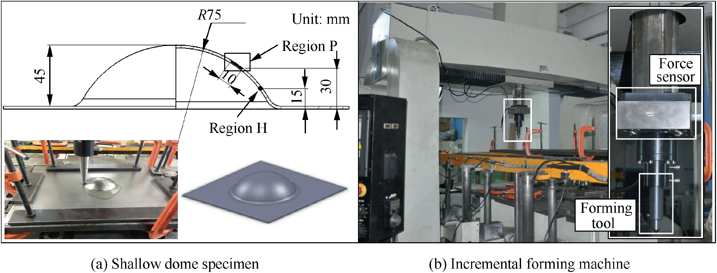
Fig. 3 Specimen and incremental forming machine.

Table 3 Chemical composition of AA2024-O aluminum alloy.
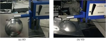
Fig. 4 Measurement of surface roughness.
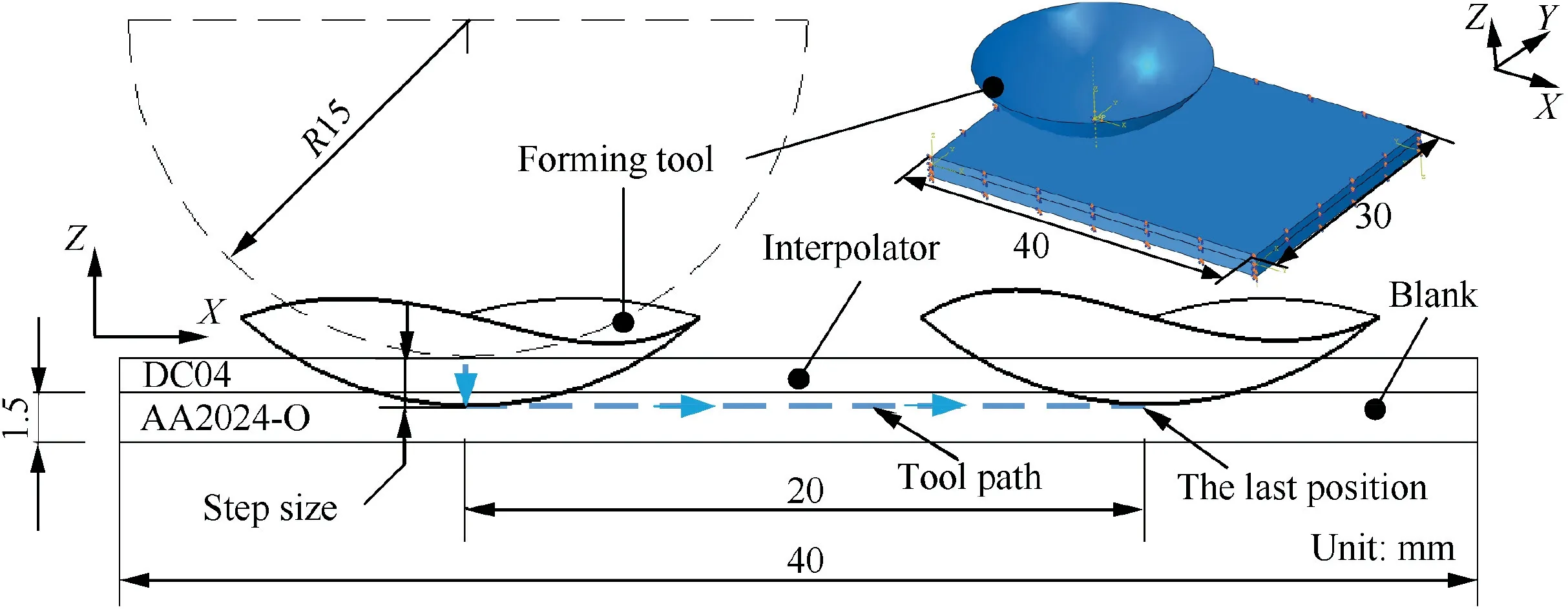
Fig. 5 Simplified simulation model for interpolator method.

Table 4 Mechanical properties of AA2024-O aluminum alloy and DC04 steel.
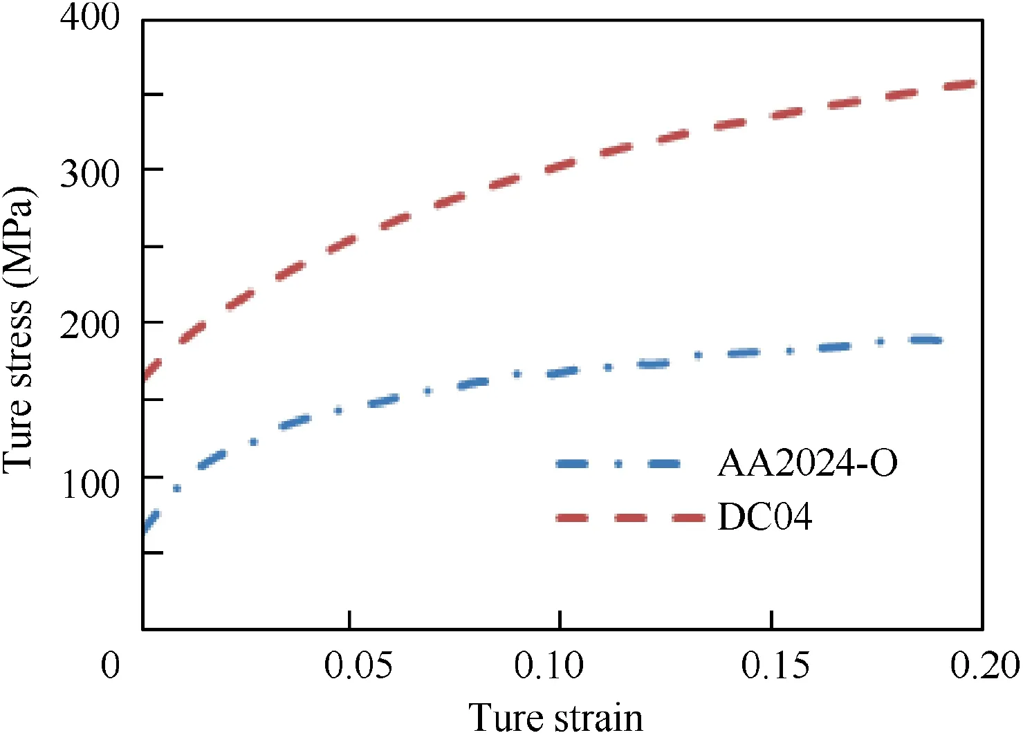
Fig. 6 True stress-strain curves of aluminum AA2024-O and steel DC04.
3. Results and discussion
3.1. Forming quality and forming force
In this section, the empirical models for forming quality (i.e.surface roughness in VD and HD and geometric error) and forming force are provided based on experimental results.According to the empirical models, both the individual and interactive effects of variables on forming quality and forming force are analyzed.
3.1.1. Surface roughness in VD
As shown in Table 5,the surface roughness along VD obtained by a roughness tester is provided. In addition, the surface roughness of the initial blank before the forming process is measured as Ra=0.35 μm and Rz=2.03 μm.
The empirical relationship between variables and surface roughness in VD is obtained with a quadratic mathematical model. Accordingly, the models of Ra(Ra,VD) and Rz(Rz,VD)in VD are given as follows:
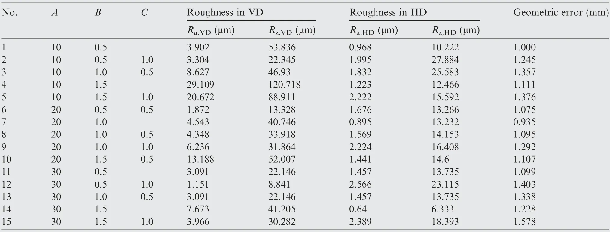
Table 5 Experimental results of surface roughness and geometric error.
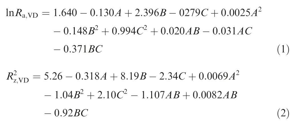
The analysis of variance (ANOVA) is adopted to examine the fitness of the established model, which includes the sum of squares (SS), the mean squares (MS), the test statistics(F-value) and proof values (P-value) for each parameter and their interaction, as presented in Table 6. In the quadratic mathematical model,the term within the model can be considered effective if the corresponding P-value is smaller than 0.05 and F-value is larger than desired value of F0.05(F0.05(1,9)=5.12, F0.05(3,9)=3.86). However, as listed in Table 6,the P-values and F-values of terms are not always confirmed to the desired value.
Therefore, the eligible terms are selected to re-establish the model by excluding the terms with P-value larger than 0.05.The re-established models of Ra,VDand Rz,VDare as follows.

The ANOVA results of the re-established models present that the P-values and F-values of all terms are eligible as listed in Table 7. The high correlation coefficient values(R2=92.74% for Raand R2=96.83% for Rz) of the developed model indicate that the developed regression equation provides a very good relationship between the input parameters (tool diameter, step size and thickness of interpolators)and responses (Raand Rz). As indicated from Eqs. (3) and(4), the influence of interpolator thickness on the surface roughness in VD is independent of tool diameter and step sizesince the interaction terms of AC and BC are not significant.This is explained by the fact that the combined influence of interpolator thickness and process parameters (tool diameter and step size) on forming force is limited as discussed in Section 3.1.3.
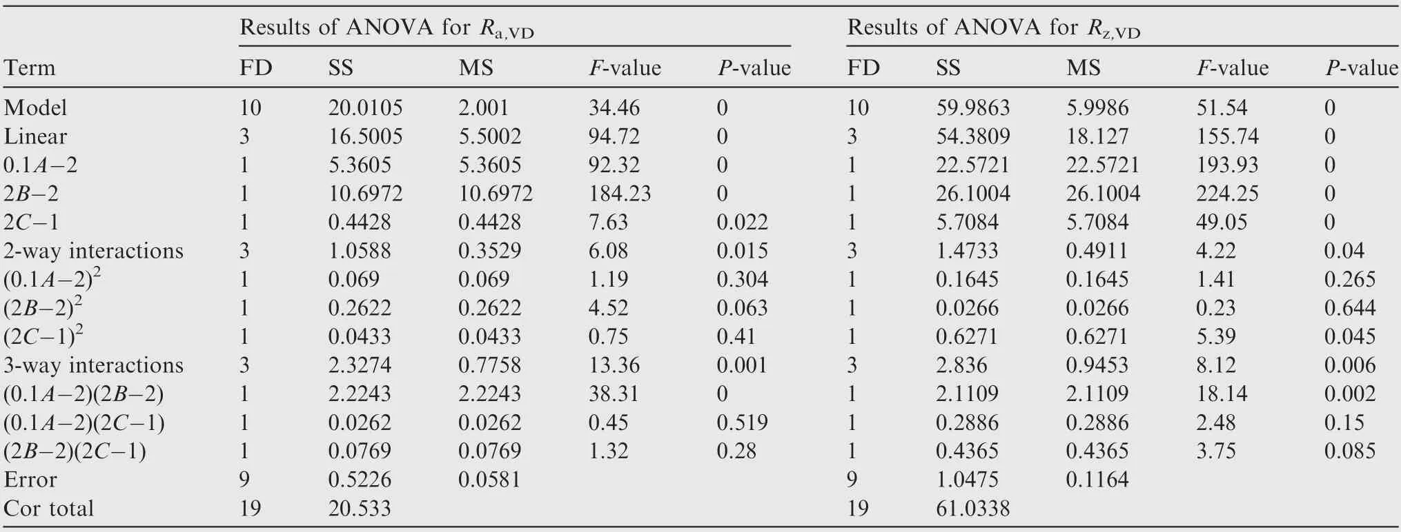
Table 6 Results of ANOVA for models of Ra,VD and Rz,VD.

Table 7 Results of ANOVA for re-established models of Ra,VD and Rz,VD.
For a more intuitive illustration, three-dimensional surface graphs are provided to present the relationships between process parameters and surface roughness in VD as shown in Figs.7 and 8.It is noted that increasing the interpolator thickness decreases the surface roughness in VD, implying that the application of interpolator effectively improves the surface quality. Meanwhile, the waved impression, namely surface roughness in VD, is caused by the extrusion deformation on the surface of blank by the forming tool. It is figured that the surface roughness in VD is decreased with the decrease of the step size and the increase of the tool diameter due to the reduction of the contact pressure. In addition, the surface roughness in VD decreases with an increase in the product of tool diameter and step size due to the combined influence on forming force.
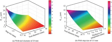
Fig. 7 Three-dimensional surface of Ra,VD.
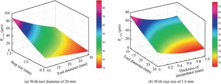
Fig. 8 Three-dimensional surface of Rz,VD.
3.1.2. Surface roughness in HD

The results of surface roughness in HD are also shown in Table 5.Adopting the same method mentioned in Section 3.1.1,excluding the ineligible terms, the model of Rain HD (Ra,HD)is established as follows:The results of ANOVA is presented in Table 8 and the value of R2(90.79%)indicates that the model is effective.Similar to the surface roughness in VD, the interaction terms of AC and BC are not significant either.Therefore,the combined influences between thickness of interpolators and process parameters (tool diameter and step size) on surface roughness can also be neglected.
The three-dimensional response surfaces of Rain HD are provided in Fig. 9. It is depicted that an increase in thickness of interpolators obviously increases the roughness Rain HD.However, compared with that of thickness of interpolator,the tool diameter and step size have less influence on roughness Rain HD, since the value of surface roughness is determined by the roughness of forming tool or interpolator. Comparing the surface roughness at different directions,the surface roughness in HD is obviously smaller than that in VD indicating that the waved impression in VD is the dominant factor affecting the surface quality in TPIF.
In addition, the models of Rzin HD can be defined as follows.

Nevertheless,the input parameters(tool diameter,step size and thickness of interpolators) have less effect on the value of surface roughness Rzin HD since the P-values are more than0.05 and F-values are less than desired value (F0.05(1,9)=5.12,F0.05(3,9)=3.86).The surface compressive stress on the surface of blank caused by forming tool and interpolator could suppress the peak height of surface roughness in HD leading to the insignificant effect of input parameters on surface roughness Rz.
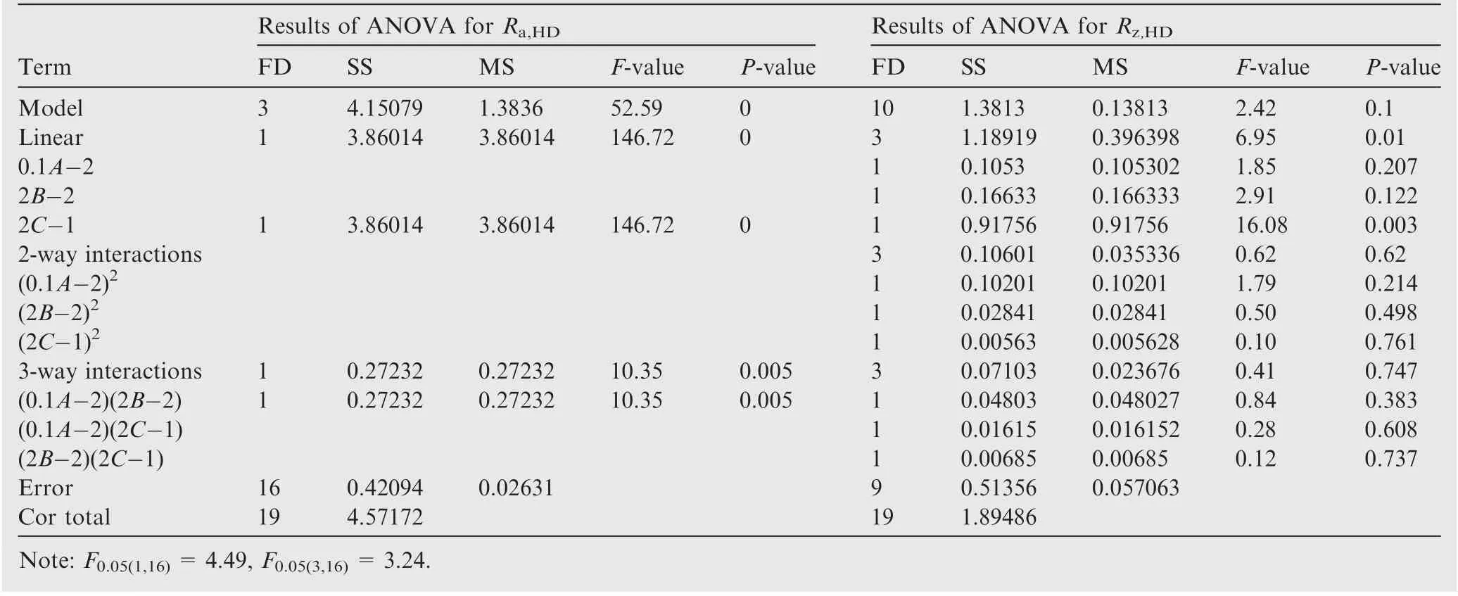
Table 8 Results of ANOVA for models of Ra,HD and Rz,HD.
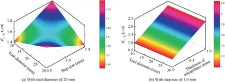
Fig. 9 Three-dimensional surface of Ra,HD.
3.1.3. Forming force
Through a three-axis force sensor, the forming forces in three directions(Fx,Fyand Fz)are obtained where Fxand Fyare the in-plane forces along X and Y directions and Fzis the axial force along the Z direction. The total resultant force (FT)and the in-plane resultant force (Fxoy) are defined as,

The total resultant force (FT), in-plane force (Fxoy) and axial force (Fz) are compared in Fig. 10.
Since the specimen is a variable-slope shape, the average forming force changes with the forming angle(α),as described in Fig. 11. Aerens et al.22,23investigated the influences of process parameters on forming force and proposed an empirical model which is effective to predict the forming force in SPIF.Based on the proposed empirical model,20,21the relationship between in-plane force and the axial force (Fz) can be simplified as follows:

Then,the forming force Fzis selected as the research object.The relationship between axial force (Fz) and process parameters (tool diameter and step size) in previous study20can be expressed as:

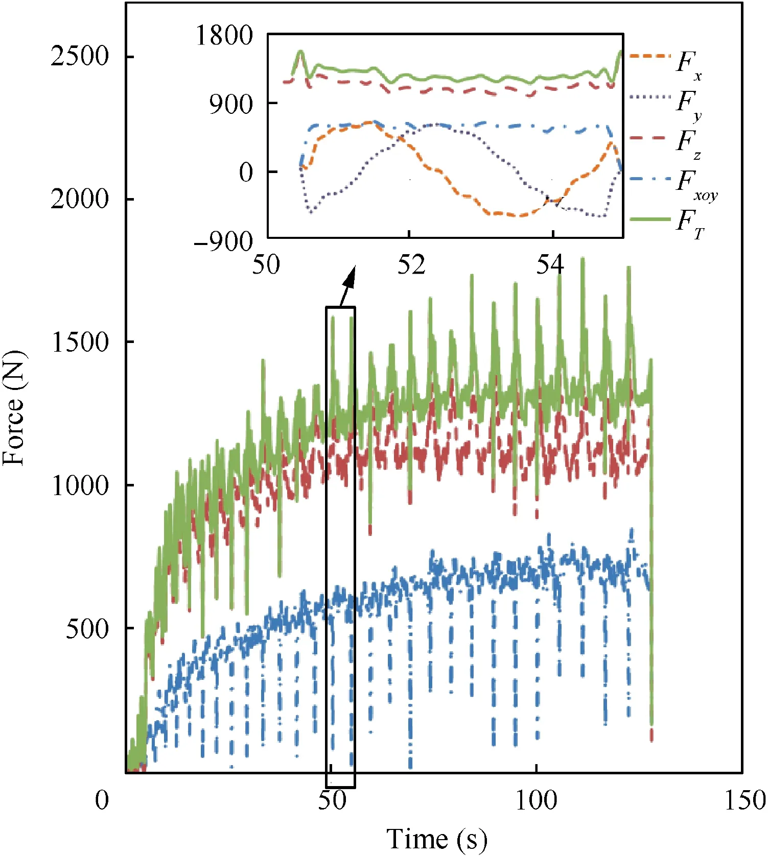
Fig. 10 Forming forces during TPIF.
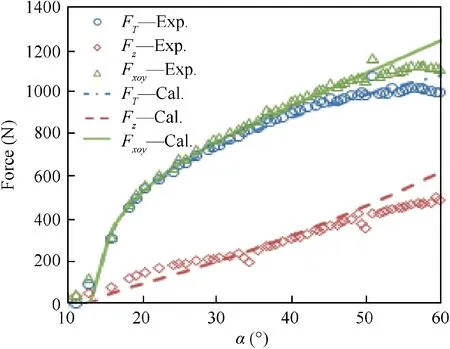
Fig. 11 Forming force of experimental and calculated results with various α (specimen No.1).

Table 9 Correlation coefficient values of force with various process parameters.
For the specimens formed without an interpolator,the correlation coefficient values of Fz(R2z) and Fxoy(R2xoy) are obtained as listed in Table 9. It is shown that the Eq. (10) is efficient to describe the relationship between forming force and process parameters because of a high correlation coefficient values (R2z>94%, R2xoy>70%). As presented in Eq.(10), preforming angle of 14 degrees is caused by the tension effect of blankholder with a force of 2300 N. It is noted that the tool diameter has more significant influence on forming force compared with the step size. As depicted in Fig. 11, the calculated forming force (Cal.) is compared with experimental results (Exp.) in terms of specimen No.1 (step size of 0.5 mm and tool diameter of 10 mm).
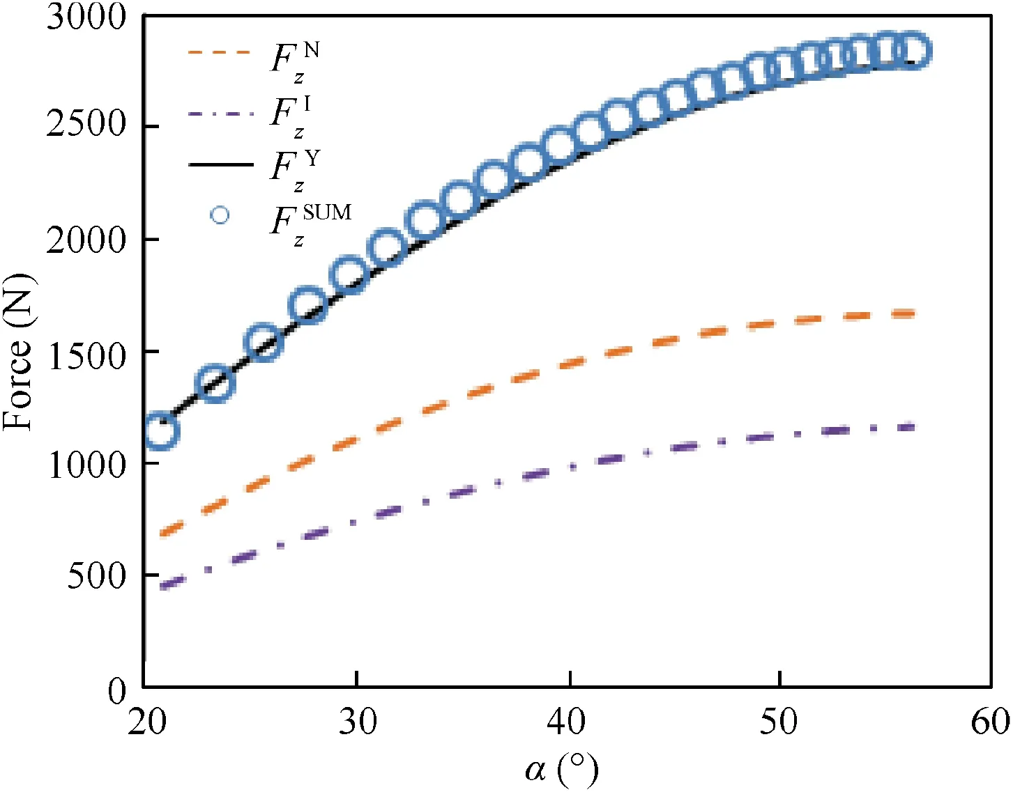
Fig. 12 Experimental values of axial force with and without interpolator and pure interpolator (step size of 1.5 mm and tool diameter of 30 mm).
Then,the influence of interpolator on forming force is studied. Using the same process parameters (step size of 1.5 mm and tool diameter of 30 mm),the specimens with an interpolator (thickness of 0.5 mm) and without an interpolator are formed respectively.The experimental values of the axial force with (FzY) and without (FzN) an interpolator are shown in Fig. 12. Meanwhile, a forming experiment for pure interpolator is carried out and the measured force FzIis also described in Fig.12.In addition,the sum forming force(FzSUM)of pure specimen (without an interpolator) and pure interpolator is defined as following:
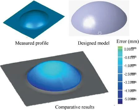
Fig. 13 Distribution of geometric error for specimens.

As shown in Fig.12,the value of FzSUMis in close proximity to the value of FzYindicating that the forming force of specimen formed with an interpolator is the sum forming force of pure specimen and pure interpolator.Therefore,the placement of interpolator has little effect on the effective forming force for deforming the pure specimen.
3.1.4. Geometric error
The profiles of the formed parts are measured with a threecoordinates measuring machine (CMM). Then, by comparing the measured profile with the designed model of the dome,the distribution of the geometric deviation is obtained with the software Geometric Studio, as shown in Fig. 13. Meanwhile,the values of root mean square error (RMSE) are defined as the geometric errors(δRMSE)of specimens which are also listed in Table 5.
Then,the model of geometric error is established as follows.

As listed in Table 10,the P-values are less than 0.001 and Fvalues are more than desired value (F0.05(1,14)=4.60, F0.05(3,14)=3.34, F0.05(5,14)=2.96) indicating that the selected terms are significant for geometric error. In addition, the model with R2of 91.08%is efficient to predict the relationship between the process parameters and the value of geometric error.Similar to the surface roughness,the combined influencebetween thickness of interpolators and process parameters(tool diameter and step size) on geometric error can also be neglected since the interaction terms are ineligible.

Table 10 Results of ANOVA for model of geometric error.
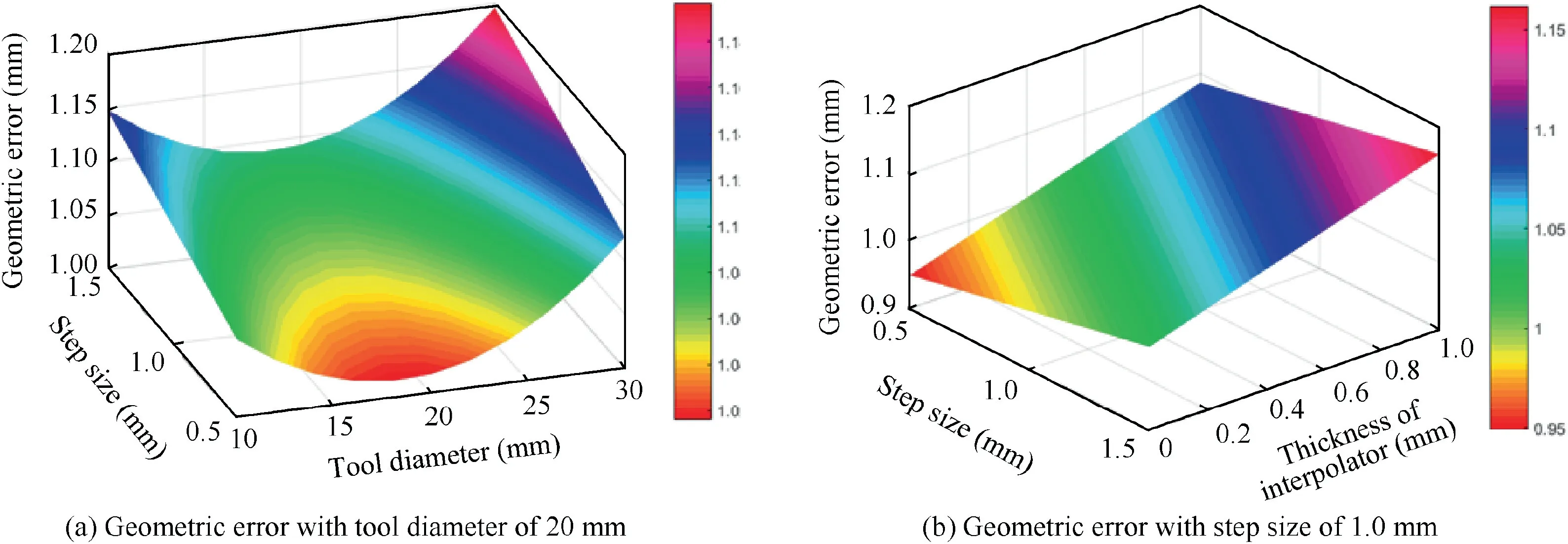
Fig. 14 Three-dimensional surface geometric error.
As shown in Fig. 14, three-dimensional surface graphs of geometric error are provided. It is figured out that geometric error increases with an increase in step size.However,the geometric error decreases firstly and then increase with an increase in tool diameter where the geometric error is smallest with a tool diameter of 18.5 mm. Meanwhile, the geometric error increases with an increase in thickness of interpolator as a result of the thinning of interpolator.
3.2. Mechanism of interpolator on surface quality
In this section, based on the simulation and experimental results, the influence mechanisms of interpolator on surface roughness in both VD and HD are analyzed.
3.2.1. Influence of interpolator on surface roughness in VD
The experimental observation shows that the use of interpolator effectively decreases the surface roughness in VD.In terms of the underlying mechanism, Martins et al.24suggested that the interpolator method decreases the roughness by increasing the tool diameter. To further verify this, the roughness values of specimens formed without an interpolator (C=0.0) and with the interpolators of 0.5 mm (C=0.5) and 1.0 mm(C=1.0) are predicted respectively based on Eqs. (3) and(4), as shown in Fig. 15. Meanwhile, the roughness values of C=0.0 with the increase of tool diameter of 0.5 mm(B+0.5) and 1.0 mm (B+1.0) are also depicted in Fig. 15.It is figured that the roughness of B+0.5 and B+1.0 are obviously larger than those of C 0.5 and C 1.0 for both of Raand Rz, implying that the influence of interpolator is more prominent than increasing the tool diameter by the value of interpolator thickness.
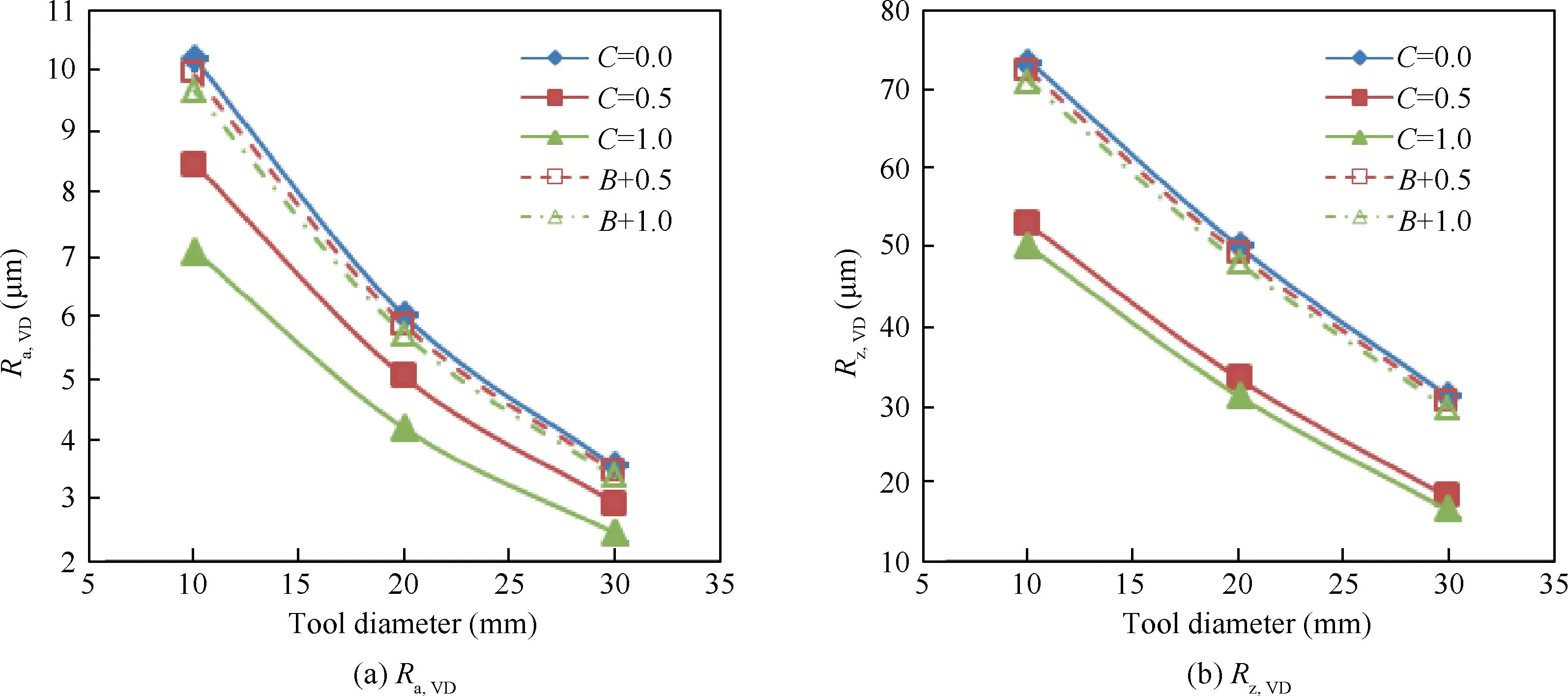
Fig. 15 Influence of interpolator and increase of tool diameter on surface roughness.
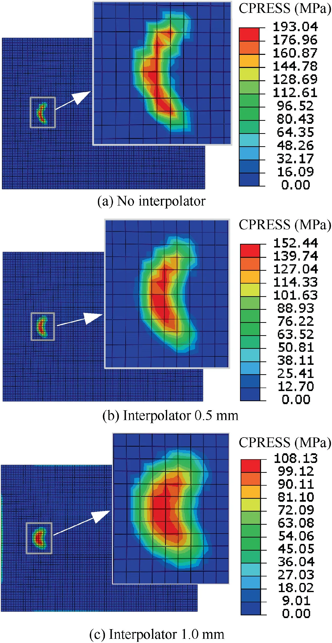
Fig. 16 Contact pressure of specimens with different interpolator.
The last position (Fig. 5) in simplified simulation forming process is chosen to investigate the mechanism of interpolator on improving surface quality.Meanwhile,as shown in Fig.16,the contact normal pressures of specimens with interpolator are more uniform than those without interpolator.Meanwhile,the contact area and the max contact pressure are obtained as shown in Fig. 17. It is figured out that the placement of interpolator and the increase of interpolator thickness significantly enlarge the contact area while reduce the max contact pressure.Meanwhile, the waved impression, namely surface roughness in VD, is caused by the extrusion deformation on the surface of blank by the forming tool. Because the decrease in contact pressure reduces the extrusion deformation reflecting by the waved impression, so the surface quality is improved since the surface roughness in VD is the major surface problem in ISF.
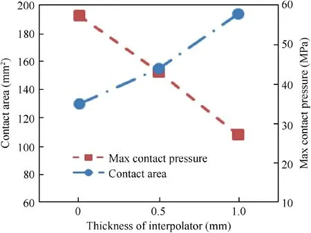
Fig. 17 Influence of interpolator on contact area and max contact pressure.
The Saint Venant’s Principle can be utilized to explain the reduction of the contact pressure for the interpolator method.According to Saint Venant’s Principle, the stress decreases with an increase of the loading distance. Therefore, as shown in Fig. 18, the contact area of the blank with the interpolator is increased compared with that directly contacting with the forming tool. As a result, the contact pressure is reduced and distributed more uniform (shown in Fig. 18) with the placement of interpolator since the contact force keeps at the same level as aforementioned.
3.2.2. Influence of interpolator on surface roughness in HD
For the specimen formed without an interpolator,the blank is directly contacted with the forming tool,leading to the sliding friction as the forming tool moving along tool path.However,as the specimen formed with an interpolator, the forming tool is contacted with the interpolator during forming process.Since the relative position between the blank and the interpolator is not changed, the sliding friction is eliminated. However, the interpolator method shows worse surface roughness in HD compared with the traditional method as lacking of burnishing efficacy of the forming tool, which is similar to the effect of acetal forming tool.17
In traditional method,‘‘orange peel”can be observed at the non-contacted surface with the forming tool caused by large strain,18,25-27which shows worse surface quality compared with the contacted surface with forming tool. This indicates that the surface compressive stress could suppress the roughness caused by large strain. Therefore, the surface roughness in HD will be increased with an increase of interpolator thickness due to the reduction of surface compressive stress.
4. Conclusion
In this paper, the influences of three variables (e.g. tool diameter, step size and thickness of interpolator) on the forming quality (e.g. surface roughness, forming force and geometric error) are investigated. Based on experimental results, the empirical models of forming results are established. Then,the influence mechanism of the interpolator method is analyzed based on the simulation and experimental results. The following conclusions can be drawn:
(1) The placement of interpolator has little effect on the effective forming force for deforming the pure specimen.The surface roughness in VD, caused by the extrusion deformation reflecting by the waved impression, is reduced with the placement of interpolator since the contact pressure is reduced and distributed more uniform with the invariable contact force.
(2) The interpolator method can eliminate the sliding friction on the surface of blank since the relative position between the sheet and the interpolator is not changed in the forming process. The surface roughness in HD of interpolator method shows worse surface quality compared with that of the traditional method due to the lack of the burnishing efficacy of the forming tool.The surface roughness in HD decreases with a decrease in thickness of interpolator since the increase of contact pressure suppresses the roughness caused by large strain.
(3) The combined influence between thickness of interpolators and process parameters(tool diameter and step size)on surface roughness is limited.The surface roughness in VD decreases with the decrease in step size and the increase in tool diameter. However, the value of surface roughness in HD has little variation with different tool diameter and step size since the value of surface roughness is determined by the roughness of forming tool or interpolator.

Fig. 18 Contact pressure for different surfaces of 1.0 mm interpolator.
(4) The geometric error increases with an increase in step size. However, the geometric error decreases firstly and then increase with an increase in tool diameter where the geometric error is smallest with a tool diameter of 18.5 mm.Meanwhile,the geometric error increases with an increase in thickness of interpolator due to the thinning of interpolator.
Declaration of interest statement
The authors claim that we do not have any commercial or associative interest that represents a conflict of interest in connection with the work submitted.
Acknowledgements
The authors thank the support from the National Natural Science Foundation of China (51575028), National Natural Science Foundation of China(51605258)and the Fundamental Research Funds for the Central Universities of China(YWF-18-BJ-J-75).
 CHINESE JOURNAL OF AERONAUTICS2020年10期
- CHINESE JOURNAL OF AERONAUTICS的其它文章
- A novel surrogate modeling strategy of the mechanical properties of 3D braided composites
- A user-friendly yield criterion for metals exhibiting tension-compression asymmetry
- Aerodynamic characteristics of morphing wing with flexible leading-edge
- High cycle fatigue failure with radial cracks in gears of aero-engines
- Motion equations of hemispherical resonator and analysis of frequency split caused by slight mass non-uniformity
- Light weight optimization of stratospheric airship envelope based on reliability analysis
