Energy principle and material removal sequence optimization method in machining of aircraft monolithic parts
Yinfei YANG, Longxin FAN, Ling LI,*, Guolong ZHAO, Ning HAN,Xioyue LI, Hui TIAN, Ning HE
a College of Mechanical & Electrical Engineering, Nanjing University of Aeronautics and Astronautics, Nanjing 210016, China
b AVIC Xi’an Aircraft Industry (Group) Company LTD, Xi’an 710089, China
KEYWORDS Aircraft monolithic part;Distortion;Initial residual stress;Material removal sequence;Strain energy
Abstract In the machining process of aircraft monolithic parts, the initial residual stress redistribution and structural stiffness evolution often lead to unexpected distortions. On the other hand,the stress redistribution and stiffness reduction during the machining process depend on the material removal sequence. The essence of the stress redistribution is releasing the initial elastic strain energy. In the present study, the influence of the material removal sequence on the energy release is studied. Moreover, a novel optimization method is proposed for the material removal sequence.In order to evaluate the performance of the proposed method,the mechanism of the machining distortion is firstly analyzed based on the energy principle.Then a calculative model for the machining distortion of long beam parts is established accordingly.Moreover,an energy parameter related to the bending distortion and the procedure of the material removal sequence optimization is defined.Finally,the bending distortion analysis and material removal sequence optimization are performed on a long beam with a Z-shaped cross-section.Furthermore,simulation and experiments are carried out.The obtained results indicate that the optimized sequence results in a low distortion fluctuation and decreases the bending distortion.
1. Introduction
Aircraft monolithic parts are widely used in the aerospace industry.1,2Studies show that over 90% of the blank material is removed during the machining of monolithic parts.3Machining distortion is a common problem in the manufacturing process of these parts in the aviation industry,which causes unexpected nonconformance parts, rework cost and delays.4,5
The initial residual stress in the blank material is one of the main factors leading to machining distortion.6,7Reviewing the literature indicates that the correlation between the machining distortion and the initial residual stress has been extensively studied so far. Nervi, et al.8established a mathematical model to predict the machining distortion based on initial residual stresses. The results indicated that the installation position of the workpiece causes relatively large distortion in the thinwalled parts. Husson, et al.9studied the influence of the residual stress on the machining distortion of gears. They showed that the residual stress through the semi-finished product can be adjusted by the heat treatment and the processing deformation can be reduced. Gao, et al.10studied the correlation between the distortion and initial residual stress by establishing a semi-analytical model. The results showed that the final machining distortion is basically determined by the residual stress within a certain thickness under the blank surface when the residual stress symmetrically distributes along the midplane in the thickness direction.
Many scholars have conducted numerous investigations on the distortion control based on the material removal strategy optimization.Cerutti,et al.11analyzed the influence of parameters of the machining process plan such as the machining sequence on the machining quality. They showed that a machining sequence that offers a gradual redistribution of the residual stresses improves the machining accuracy. Wu,et al.12used a quasi-symmetric machining method to reduce the distortion when machining a 7075 aluminum alloy aeronautical monolithic component. They observed that the maximum deformation value is within 20% of that when using a conventional one-side machining method. Urrest, et al.13proposed a machining model to predict the in-process disc behavior during the roughing and finishing operations. They found that when the machining paths change during the roughing process of a turbine disk,the corresponding distortion reduces so that less compensation is required to achieve the desired disc profile shape.Liu,et al.14performed the finite element analysis of the turning process and broaching process of a turbine disk.The comparisons of three different mortise broaching strategies revealed that strain energy decreases at the fastest speed and deflection varies steadily with the lowest level of magnitude.
Reviewing the literature indicates that much investigations have also been conducted on the machining distortion control by other means. Li, et al.15analyzed the effects of cutting depth on the redistribution of the residual stress.They demonstrated that the magnitude of distortion and residual stress can be decreased and optimized efficiently by controlling and optimizing the cutting depth in the roughing and finishing.Brinksmeier, et al.16investigated the gear manufacturing process to minimize shape deviations. The results indicated that the partition of the material removal allows controlling the amplitude and direction of distortion after case hardening. Yang, et al.17studied the machining distortion of a typical part at different locations of the blank material by the finite element method and concluded that an appropriate part location can effectively reduce the distortion of parts.
In summary, extensive investigations have been conducted so far on the residual stress and minimizing the final distortion in the milling of monolithic aircraft parts. However, little attention has been paid to the machining distortion stability in the finishing stage.The machining distortion stability represents the fluctuation degree of the machining distortion. Studies show that large fluctuations result in high uncertainty and unstable machining distortion, thereby affecting the shape accuracy and assembly consistency. Meanwhile, the release of the stored elastic energy is the main factor affecting the machining distortion. If most of the energy is released during the roughing stage without concerning the machining distortion, the machining distortion stability can be improved.
In the present study,it is intended to investigate the energy release mechanism of the machining distortion. Moreover, an analytical model will be established for the bending distortion of long beam parts. Then an energy parameter related to the bending distortion and a procedure of the material removal sequence optimization will be defined accordingly. Finally, a case study including the theoretical calculation, simulation and machining experiment will be carried out.
2. Energy principle of machining distortion
2.1. Energy release mechanism of machining distortion
Compared with the yield limit of the material, the residual stress value is small,and the material maintains linear elasticity throughout the machining process. Meanwhile, the neutron diffraction method proves that the machining process can only cause the redistribution of stress without the occurrence of a stress relaxation phenomenon.18It is worth noting that the machining-induced residual stresses usually exist in the surface layer of the workpiece.6,19By optimizing the tool parameters and cutting parameters, the machining-induced residual stresses and its effective layer thickness can be significantly reduced.For thick wall aircraft monolithic parts, the influence of the machining-induced residual stresses on the machining distortion is less than the initial residual stress.6,20,21,22,23Most aircraft load-bearing components are thick-walled structures and the wall thickness is often 6-12 mm.Therefore,the following reasonable assumptions are made for the machining distortion analysis in the present study: (1) Ignore the influence of machining heat and temperature variation on machining distortion. (2) Ignore the change of kinetic energy of the parts during the machining process. (3) Ignore the impact of machining-induced residual stress on thick aircraft monolithic parts made from easy-to-cut materials, such as the aluminum alloy.
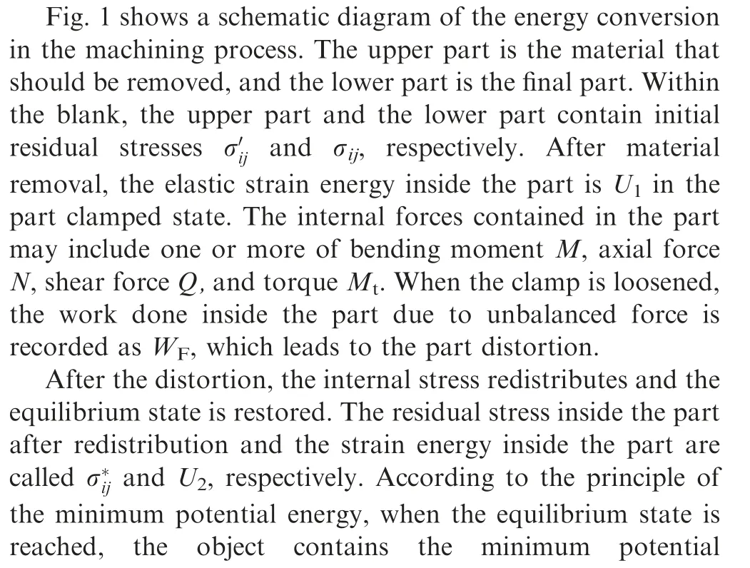

Fig.1 Energy release mechanism of machining distortion.


According to the abovementioned analysis, the machining distortion is caused by the elastic strain energy release inside the remaining material rather than the removed material.Moreover,the distortion form may be a single form or a combination of several forms such as stretching,bending,twisting,and shearing.
2.2. Analytical model of machining distortion of a long beam
Fig.2 shows a schematic drawing of the material removal process. In a beam with the size of B×H×L, all the materials except for the final part are divided into n units along the longitudinal direction on the cross-section. The minimum width and height of each unit are equal to the cutting width and cutting depth,respectively.In order to improve the computational efficiency,the unit size can be increased several times.For prestretched plates,the distribution of the initial residual stress in different sections along the rolling direction is considered to be identical.25,26Therefore, the unit length can be equal to the part length (Fig. 3).
Assuming that one unit is removed in one machining step in Fig. 2, n steps are required from blank to the final part.Regardless of any processing constraints, there are n! possible material removal sequences. When removing the unit according to sequence i, the unit removed at step j is expressed as sij, where i=1,2,...n!, j=1,2,...n.
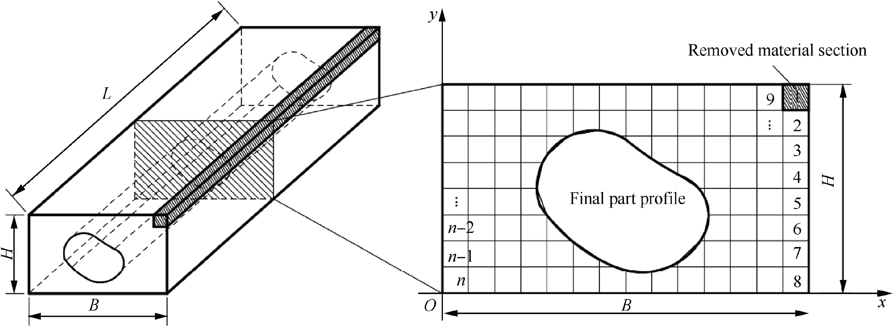
Fig.2 Schematic diagram of material removal sequence.

Fig.3 The maximum deflection value.
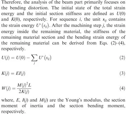
When analyzing the bending distortion of a long beam,one end of the beam is fixed and the other end is hinged.Moreover,the part can be simplified into a simply supported beam. The maximum deflection value is used to characterize the distor-
tion.7,8,14The correlation between part distortion, bending strain energy and stiffness is described as:

where ω and L denote the maximum deflection value and the length of the beam, respectively.
The analytical model can calculate the distortion at each machining step. In fact, the part may be machined with onetime clamping and the distortion cannot be observed and measured before loosening the clamp. Therefore, the calculated distortion can be regarded as the potential distortion of parts.
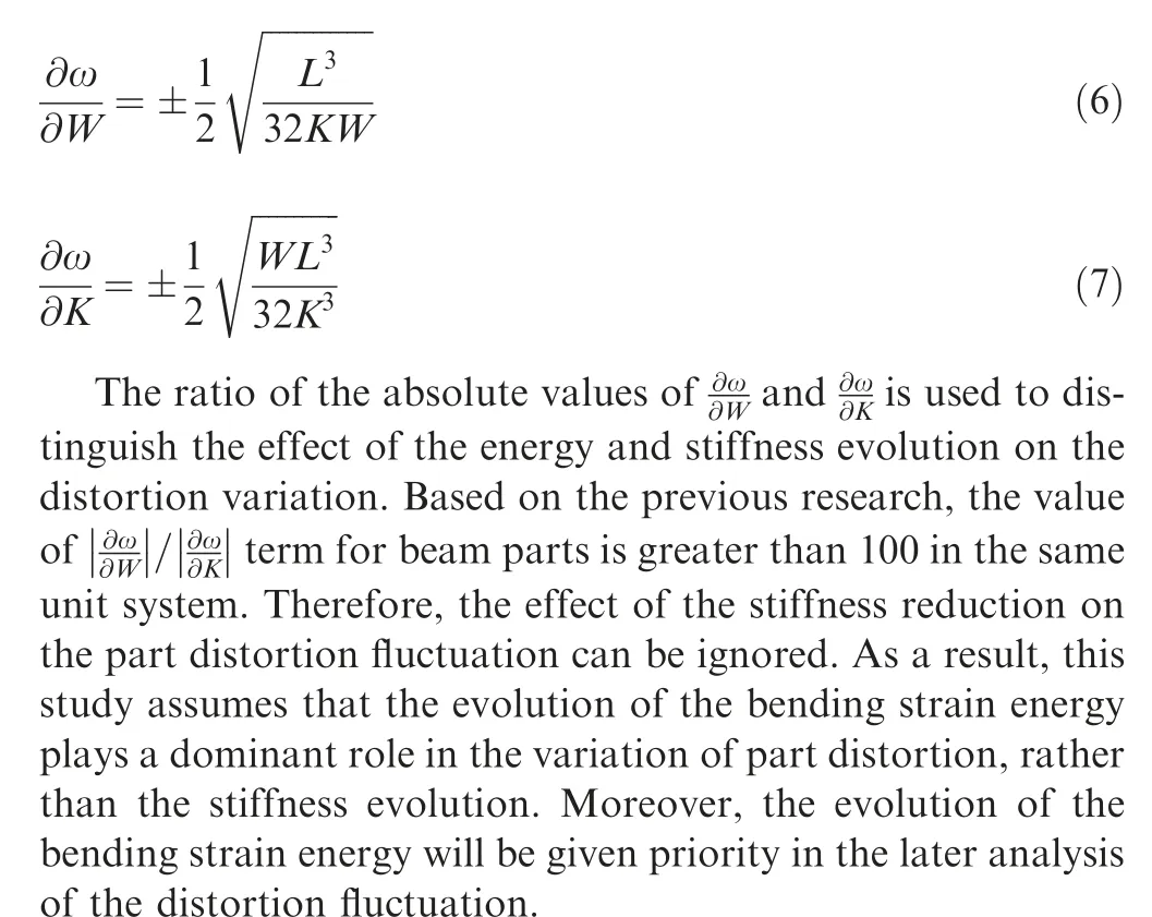
According to Eq.(5),the distortion value ω is a function of the bending strain energy W and stiffness K. In order to analyze the influence of the stiffness evolution and energy evolution on the variation of the part distortion, the partial derivatives of ω to W,and ω to K,are listed in Eqs.(6)and(7).
3. Optimization method of material removal sequence
3.1. Energy parameter related to bending distortion
Based on the assumption that energy plays an absolutely dominant role in the distortion, the machining distortion stability can be controlled by adjusting the energy release sequence.During the machining process, the evolution of the bending strain energy inside the remaining material is complex, which is different from the monotonous decrease of the total strain energy. In order to control the evolution of the bending strain energy and further control the distortion stability, a new parameter W*is defined as the bending potential energy inside each unit.The sum of the bending potential energy of all units is defined as W*total.The bending potential energy quantifies the influence of the initial residual stress on the bending distortion of the final part.The expression of W* of unit k is mathematically described as the following:

where A(k), Yaxisand σm(k) denote the section area of unit k,the distance between part centroid to X-axis and the average value of initial residual stress inside the unit, respectively.Moreover, IPand y(k) are the moment of inertia of the final part to its own centroidal axis and the distance from the centroid of unit k to X-axis, respectively.
3.2. Optimization of material removal sequence
If the units with high bending potential energy are removed preferentially, the total bending potential energy decreases rapidly. Moreover, during the subsequent machining process,there is not be too much bending potential energy release,and there is no high machining distortion. Therefore, the machining distortion and the fluctuation of the machining distortion are reduced, and the machining distortion stability is improved.
According to the analysis in Section 2.2, all the possible removal sequences can be expressed as a matrix S of n×n!,which is described as the following.
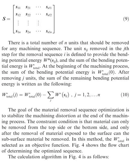
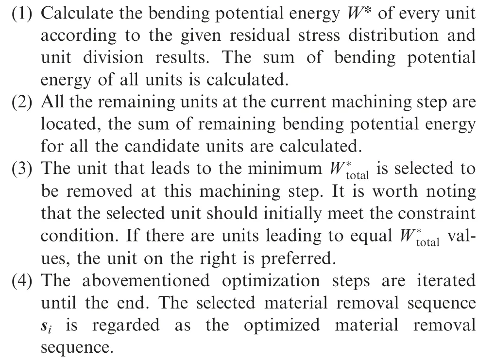
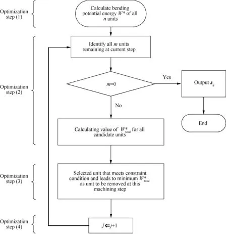
Fig.4 Flow chart of optimization method.
For the optimized material removal sequence, the part distortion value ωjat jth machining step can be calculated by Eq.(4), where j=1,2,...n. Moreover, the distortion curve corresponding to each machining step can be obtained. After removing the units with high bending potential energy preferentially,the distortion fluctuation tends to decrease.There will definitely be a stage where the distortion is most stable from a certain machining step to the last machining step.This stage is defined as the machining distortion stable stage.
For all n machining steps, the Standard Deviation value(SD)of the distortion between each step and step n can be calculated. The problem of determining the machining distortion stable stage is described as the following:
Find the machining step r. Therefore,
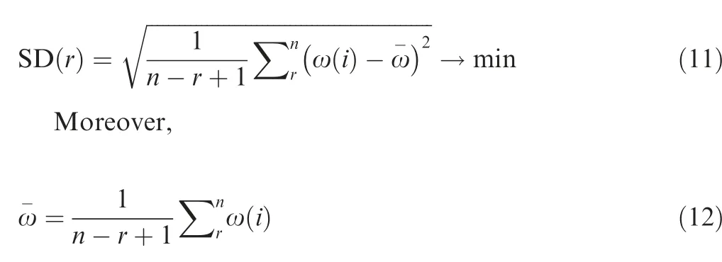
where i=r, r+1,...,n-1.The stage from machining step r to step n is defined as the machining distortion stable stage.Moreover,the machining step r is defined as the starting point of this stage.
4. Case study
4.1. Part geometry and unit division
Fig. 5 shows that a typical beam structure is used to validate the proposed model. The blank material is the pre-stretched 7050-T7451 aluminum alloy. In the following calculation and discussion analysis, the units of the dimension, stiffness and energy are mm, N/mm and mJ, respectively.
The position of the part inside the blank material significantly influences the final distortion of the machined part.8,14In order to reduce the machining distortion, the distance from the part bottom surface to the blank bottom is set to 4 mm. The prior finite element analysis shows that the expected distortion of the part caused by the initial residual stress at this position is about zero. Fig. 6 shows that according to the actual machining conditions, the section of the material that should be removed is divided into 26 units, as shown in. Moreover, the thickness of each unit is 2 mm.
4.2. Initial residual stress measurement
Crack compliance method is used to measure the initial residual stress distribution. The crack compliance method is suitable for measuring the initial residual stress inside the aluminum alloy pretension plate.26-28
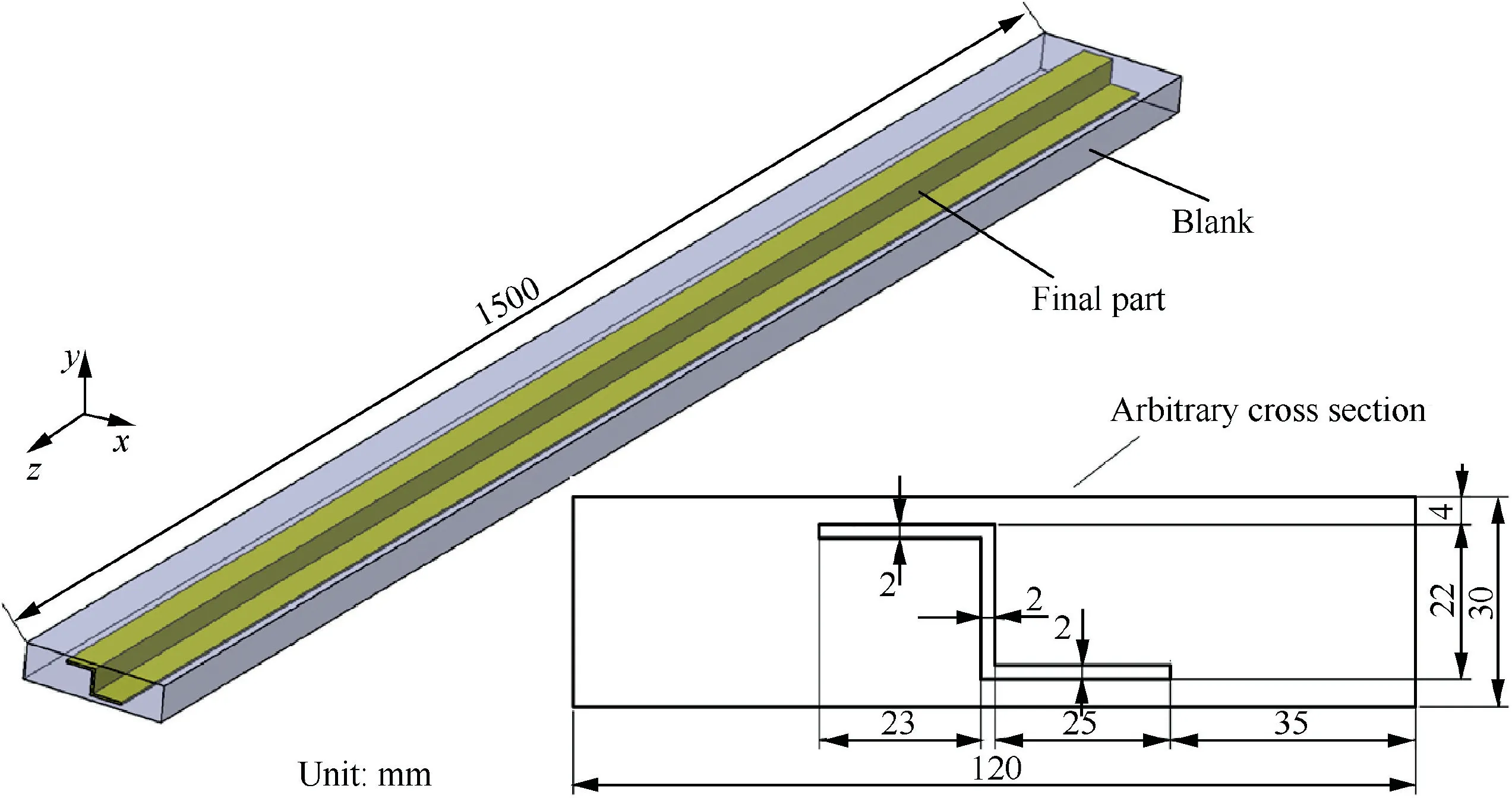
Fig.5 Schematic diagram of blank and part.
For the blank material from the same batch, the initial residual stress distribution is measured by cutting small samples from the end of the blank.Fig.7 shows the initial residual stress distribution. Since the stress amplitude in the transverse direction is lower than that in the rolling direction, and because of the Poisson’s ratio of materials, the effect of the stress in the transverse direction on the distortion along the rolling direction is less than the stress in the rolling direction.Thus,the stress in the transverse direction is ignored.This distribution curve is utilized as the initial stress conditions of the whole blank to analyze the machining distortion during the material removal process.
4.3. Material removal sequence optimization
The optimized material removal sequence is calculated using the proposed optimization method. The optimization process is as follows:
(1) Fig.8 shows that the bending potential energy W*of all 26 material units is calculated according to the measured initial residual stress distribution and unit division results in Section 4.1 and Section 4.2.It is observed that the units(1,2,3)in the top side and units(14,15,16)in the bottom side contain relatively high bending potential energy, while the energy of the other units is low.
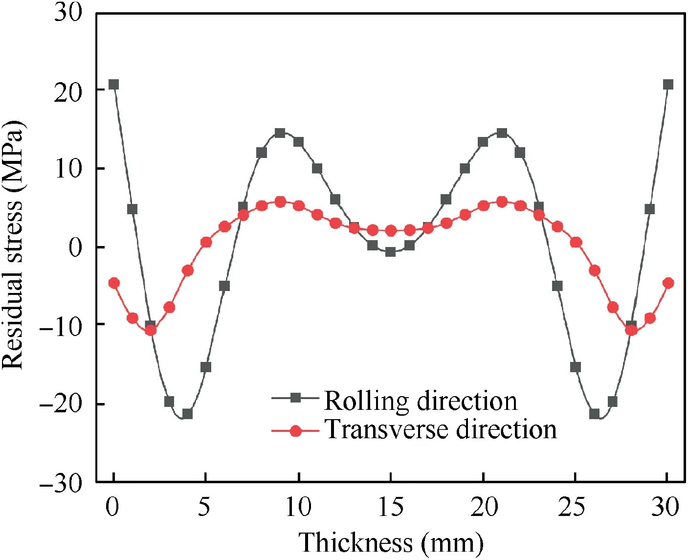
Fig.7 Initial residual stress distribution.
(2) The optimized sequence is obtained by following the optimization step (2) to step (4) in Fig. 4.
Meanwhile, two conventional material removal sequences are adopted for comparison. The conventional sequence 1 is to initially remove all the material on the top and then turn over to remove the bottom material. The conventional sequence 2 initially roughens the top by 2 mm. Then, it turns over to remove all the material on the bottom and then turns over again to finish the top. Table 1 shows the optimized sequence and the two conventional sequences.
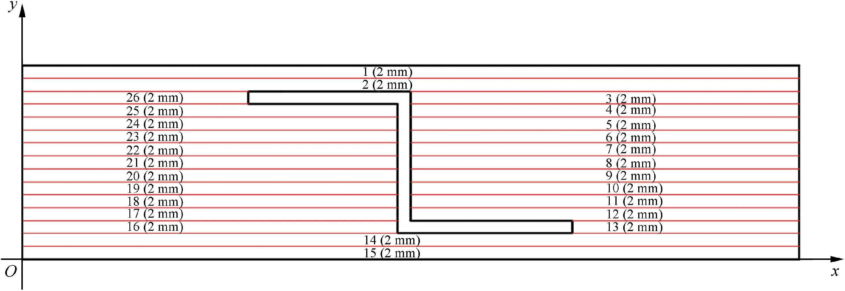
Fig.6 Division of cross-section.
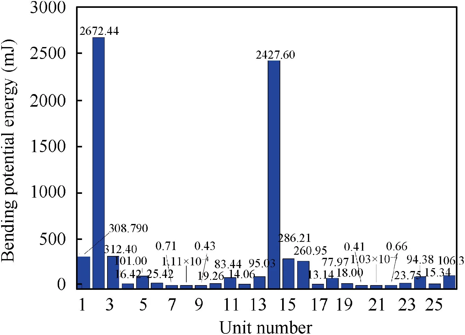
Fig.8 Bending potential energy of each unit.
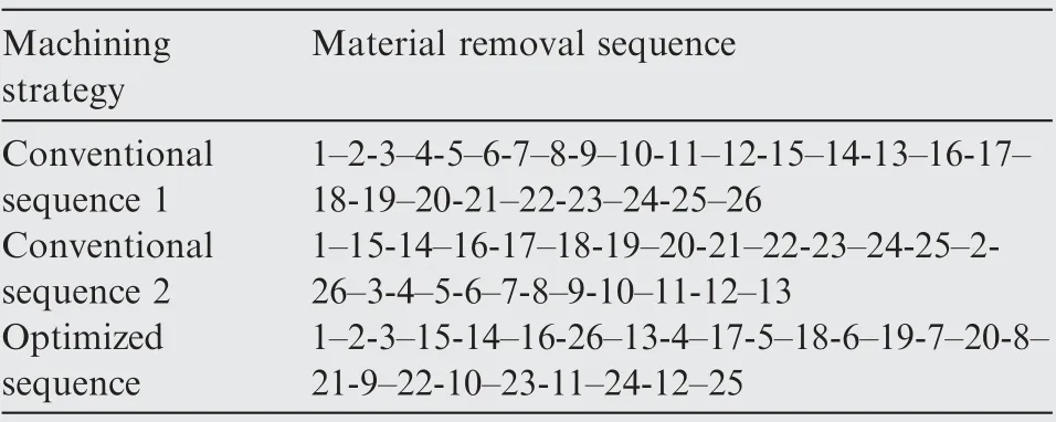
Table 1 Material removal sequence.

Table 2 Mechanical properties of 7050-T7451.
4.4. Finite element simulation
The finite element simulation(FEM)is used to simulate different material removal processes.Then,the machining distortion corresponding to each processing sequence can be obtained.29,30The simulation results are compared with analytical calculations and experimental results. Fig.5 shows that the model of exactly the same size as the blank and part is established in ABAQUS.The initial residual stress distribution in Fig. 7 is introduced as the stress condition. Fig. 9(a) shows the designed shape of the blank material with initial residual stresses.
The‘‘Birth and Death”method is used to remove the material in FEM,in which the stiffness matrix is set to zero to deactivate the element. The material is set to be isotropic and homogeneous in the simulation.Table 2 shows the mechanical properties of 7050-T7451.
The model is meshed with the C3D8R element,with a total of 307,498 elements and 336,672 nodes. The 3-2-1 constraint condition is adopted as the boundary conditions, in which the rigid motion of the workpiece is constrained. However,the workpiece can deform freely to reach a new stress equilibrium state.
Corresponding to the three material removal sequences,the simulation process is also set to 26 machining steps. Fig. 6 shows that one material unit is removed in one step. Meanwhile, the distortion value of each step is also recorded.As an example, Fig. 9 (b) shows the distortion after machining step 10 for the conventional sequence 1.
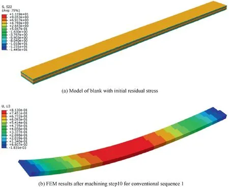
Fig.9 Finite element simulation.
4.5. Experiment setup
Machining experiments are conducted to verify the effectiveness of the proposed method.All specimens are collected from the same plate for the residual stress measurement.
Fig.10 shows that the experiments are performed on a VC-3016G vertical milling machine. Based on a large number of experiments, the tool and cutting parameters of the aluminum alloy machining are determined in this experiment, and the corresponding machining residual stress is measured. A μ-X360s X-ray stress tester is utilized to measure the machining residual stress.Test data shows that under this machining condition,the average machining residual stress and the depth are about -10 MPa and 0.03 mm, respectively. It should be indicated that a three-flute cemented carbide ∅16 end mill with a tool edge radius of 0.5 mm is employed.Cutting fluid is used to reduce the effect of the cutting heat. The same cutting parameters are performed on all specimens.The spindle speed,the feed rate, the cutting width, and the cutting depth are 18,000 r/min, 7000 mm/min, 16 mm, and 2 mm, respectively.
Table 3 shows the experiment design performed in two groups. In the experiment group 1, the reference plane of the part is always closely contacted with the working surface when the part is clamped. While in the experiment group 2,the part clamping is loosened at a special point(SP)of the process,then the part can deform freely. A gap is formed between the part and the working surface because of the distortion. Before the part is fixed again,some thin copper sheets will be plugged into the gap. Then, the four sides of the part will be fixed and the current distortion could be removed by cutting from one side of the part. The new surface will be set as the machining benchmark.
The SP differ between conventional and optimized sequences. For the conventional sequences used in industry now,the point is usually set according to the technician’s experience, which is always at the penultimate machining step in front of the last turn of the workpiece. Moreover, if the part doesn’t have enough allowance to be removed at this moment,the penultimate machining step in front of the previous turn of the part is set to be the special point. For the optimized material removal sequence, the machining benchmark can beadjusted at the starting point of the machining distortion stable stage proposed in Section 3.2.In order to avoid the random error of the experimental results, each experiment from number 1 to number 6 is repeated three times,and the final distortion result is the average value.
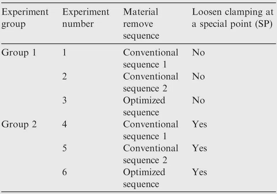
Table 3 Experiment design.
According to the abovementioned analysis, the SP for the conventional sequence 1 is set before the removal of unit 12.For the conventional sequence 2,the workpiece is turned over twice, and the SP can be set before the removal of unit 25.While for the optimized sequence, the SP is set before the removal of unit 19. The determination process will be presented in detail in the following analysis.
The final shape of the part is measured with a MISTRAL coordinate measurement machine (CMM) with 0.005 mm accuracy.50 points that are uniformly distributed in the length direction on the bottom surface of the part are measured.Comparing the measured value with the theoretical value,the machining distortion value is calculated.
5. Results and discussion
5.1. Machining distortion results
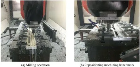
Fig.10 Experimental setup.
Fig. 11 shows the evolution of the total bending potential energy W* total corresponding to different material removal sequences. The obtained results show that the release rate of the bending potential energy corresponding to the optimized sequence is higher than that of the other two conventional sequences.
It should be indicated that the material removal process is divided into 26 steps and one unit is removed at each step.Fig. 12 shows the machining distortion results corresponding to different material removal sequences.
Fig. 12 shows that the FEM results are in good agreement with the theoretical calculation results, which proves the correctness of the analysis model.Moreover,for similar stress distributions, the machining distortion values at the beginning and the end of the machining process are fixed values.In other words, the final machining distortion is nearly identical under different machining strategies for a given initial residual stress distribution.
Fig. 12 presents that significant fluctuations of the distortion values appear in the early stage of the machining process for all three sequences.It is worth noting that the distortion of the conventional sequences still fluctuates greatly in the late machining stage, while the distortion values and fluctuations of the optimized removal sequence are much smaller. This is beneficial to control the machining distortion in the finishing process.
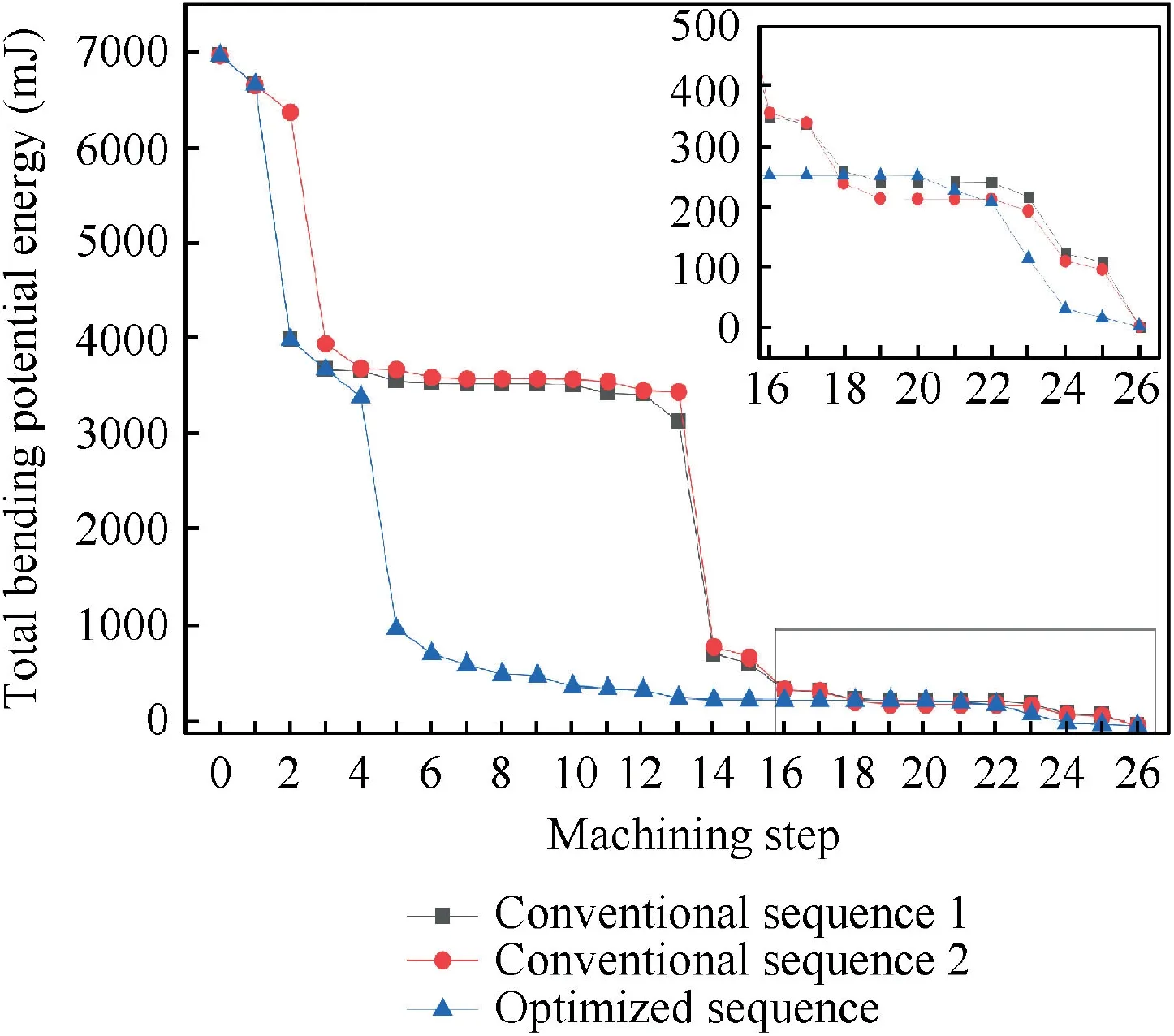
Fig.11 Total bending potential energy variation of different material removal sequences.
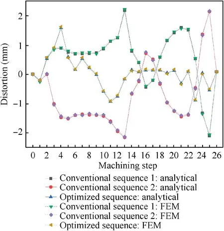
Fig.12 Distortion comparison between analysis model and FEM under different material removal sequences.
The fluctuation of the analytical distortion value for the three material removal sequences is evaluated by the standard deviation. For all machining steps, the standard deviation value of the distortion between each step and the final step is calculated. Fig. 13 shows the obtained results. It is observed that the optimized sequence corresponds to smaller distortion fluctuation compared with two conventional sequences. By optimizing the material removal sequence, the machining distortion stability can be improved in the finishing stage. Moreover, the final distortion can be reduced by re-machining the machining benchmark at an appropriate time point.
Fig.13 shows that the Standard Deviation value(SD)from 14th step to 26th step is the smallest.So the timing before 14th step is the SP for the optimized sequence. It should be indicated that the SP are only used for experiments, not for theoretical analysis and finite element analysis.
Fig. 14 shows that the final machining distortion of two groups of experiments is measured and compared with the theoretical and simulation results. The results of the experiment group 1 match the analytical and simulation results under the same process conditions.
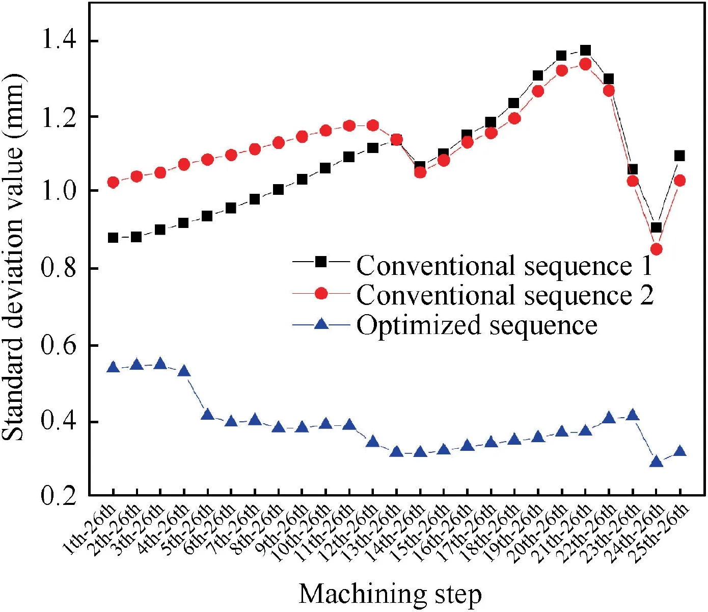
Fig.13 Standard deviation comparison results of optimized sequence.
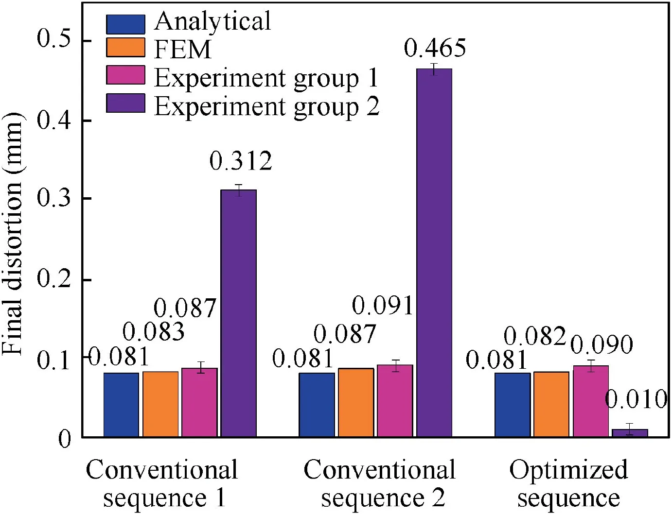
Fig.14 Final distortion comparison among three sequences.
By comparing the machining distortion results of the experiment group one and experiment group two,it is observed that the final distortion of the optimized sequence is 0.01 mm,which is reduced by 88.9 %. However, the final distortion of the conventional sequence one and the conventional sequence two are increased to be 0.312 mm and 0.465 mm, respectively,which are higher than the original final distortion in experiment group one. After re-machining the machining benchmark, the final distortion depends on both the initial strain energy and the machining strategy. When the machining distortion fluctuates significantly during the machining process,the unreasonable time point for re-machining the machining benchmark cannot reduce the final distortion.However,it will cause the distortion result to exceed the expected value.Therefore, a more stable process of the distortion and a reasonable time point for re-machining the machining benchmark is important.
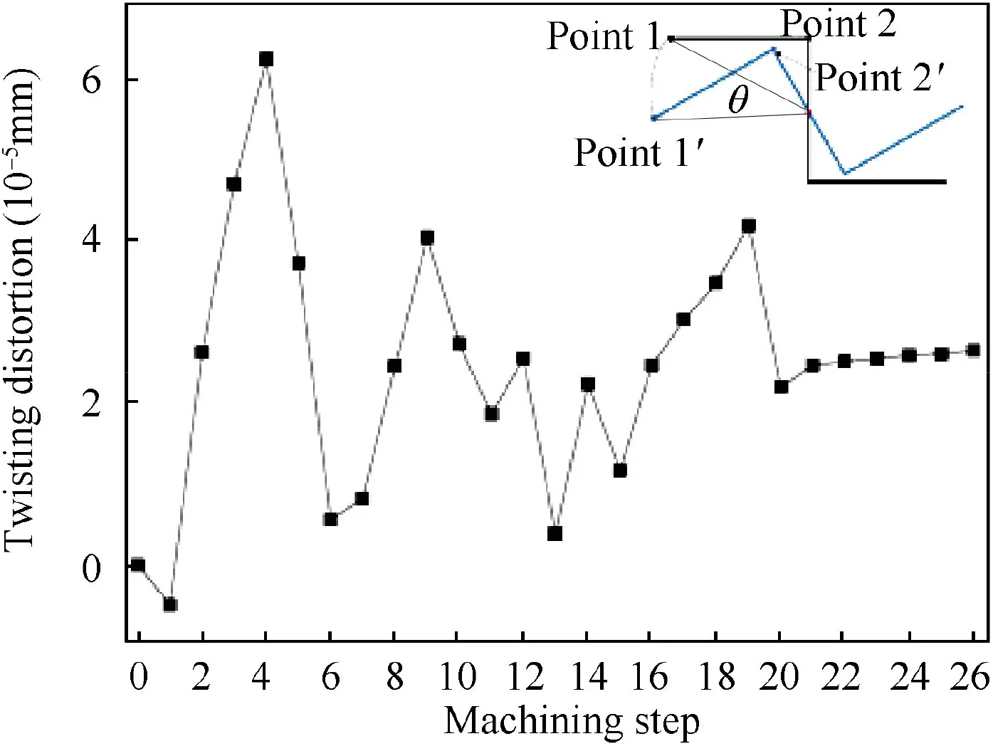
Fig.15 Twist distortion results of optimized material removal sequence.
In actual machining, there is also a certain degree of twist distortion. The simulation data of the twisting distortion in the machining process is analyzed. The twisting distortion is characterized by the twist angle or the rotational arc length of the farthest point from the cross-section center at one end of the part.
Fig.15 illustrates the twisting distortion results of the optimized material removal sequence. It is found that the amplitude of the twisting distortion is much smaller than that of the bending deformation. Similar with the changing process of the bending distortion, there are remarkable fluctuations of the twisting distortion values in the early machining stage.Moreover, the twisting distortion value and the fluctuation of the optimized removal sequence decrease in the finishing process.
5.2. Analysis of strain energy evolution during the machining process
According to the energy evolution analysis presented in Section 2.1, the bending strain energy is a part of the total strain energy. Moreover, the bending strain energy causes the part to undergo bending distortion. Fig. 16 shows the variations of the total strain energy U and bending strain energy W inside the remaining material in the theoretical analysis.
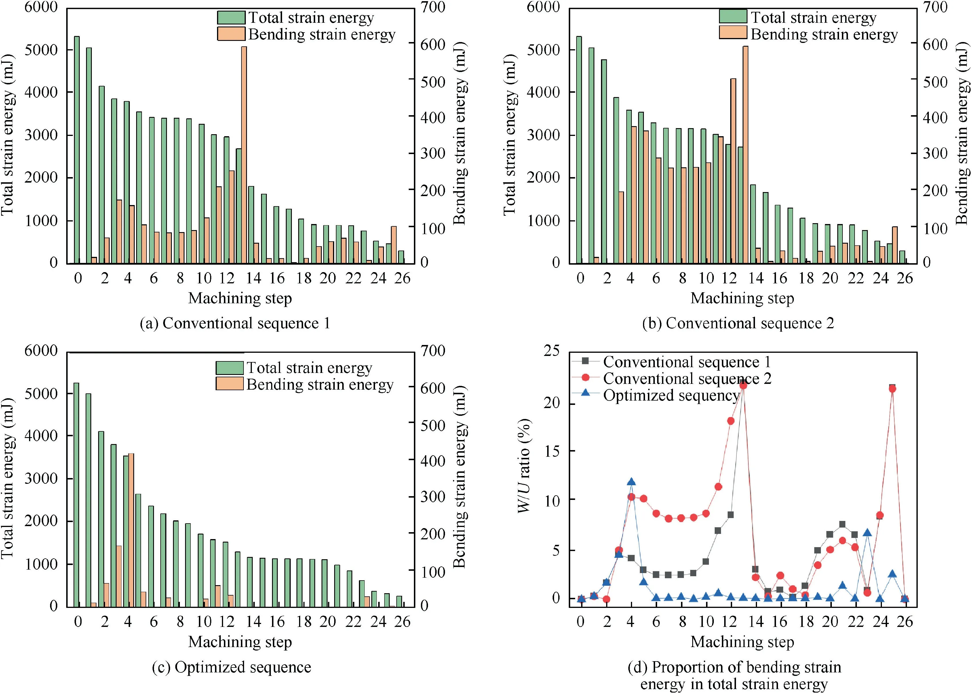
Fig.16 Theoretical analysis of energy conversion.
Table 4/values under three material removal sequences.

Table 4/values under three material removal sequences.
?
Fig. 16(a) to 16(c) show that the total strain energy monotonously decreases,while the decline rate is different for different material removal sequences. However, the bending strain energy of the remaining material does not decline monotonously. Fig. 16(d) presents the ratio of W to U of the three material removal sequences. It is observed that for the three sequences, the proportion of W to U in the process is maintained at a very low level, and the maximum value is only 22.7 %.
The bending strain energy accounts for only a part of the total strain energy, and the bending strain energy inside the remaining material does not decrease monotonously. This proves why the material removal sequence optimization is based on the bending potential energy rather than the bending strain energy.
5.3. Influences of stiffness and energy evolutions on machining distortion
developed to achieve the minimum fluctuation of the machining distortion. Therefore, a typical beam structure is taken as an example.It is observed that the results of the numerical simulation and experiment coincide with the theoretical calculation. Furthermore, the correlation between distortion and evolution of stiffness and energy are discussed. The following conclusions are drawn:
(1) The machining distortion is a function of the bending strain energy and the structure stiffness. In the machining process, the variation of the bending strain energy plays a dominant role in the variation of the machining distortion when compared with the change of the structure stiffness.
(2) Bending strain energy accounts for only a part of the total strain energy. During the machining process, the evolution of the bending strain energy inside the remaining material is complex, which is different from the monotonous decrease of the total strain energy. A new parameter is defined as the bending potential energy,which quantifies the influence of the initial residual stress on bending distortion of the final part.
(3) By the preferential removal of the unit with high bending potential energy, the total bending potential energy will decline rapidly, and the machining distortion will become small and stable. There will be a machining distortion stable phase in which the distortion fluctuation is the smallest.By controlling the machining distortion stability, the final distortion can be further reduced by remachining the machining benchmark at an appropriate time point.
(4) The bending distortion analysis model and material removal sequence optimization method proposed in this study have certain limitations. However, they provide a reference for the study on twisting, stretching and other distortions under more complex stress and structural conditions.
6. Conclusion
In the present study,an analytical model of the machining distortion based on the energy principle is established.Moreover,a novel material removal sequence optimization method is
Acknowledgment
Part of this work was supported by the National Natural Science Foundation of China (No. 51405226).
 CHINESE JOURNAL OF AERONAUTICS2020年10期
- CHINESE JOURNAL OF AERONAUTICS的其它文章
- A novel surrogate modeling strategy of the mechanical properties of 3D braided composites
- A user-friendly yield criterion for metals exhibiting tension-compression asymmetry
- Aerodynamic characteristics of morphing wing with flexible leading-edge
- High cycle fatigue failure with radial cracks in gears of aero-engines
- Motion equations of hemispherical resonator and analysis of frequency split caused by slight mass non-uniformity
- Light weight optimization of stratospheric airship envelope based on reliability analysis
