Efficiently constructing collision-free regions of tool orientations for holder in five-axis machining of blisk
Zhiwei WANG, Xiaojun LIN, Yaoyao SHI
School of Mechanical Engineering, Northwestern Polytechnical University, Xi’an, Shaanxi 710072, China
KEYWORDS Blisk;Collision-free region;Five-axis;Interference detection;Machining;Tool holder
Abstract Blisks with the integral structure are key parts used in new jet engines to promote the performance of aircrafts, which also increases the complexity of tool orientation planning in the five-axis machining. It is an essential task to find the collision-free tool orientation when the tool holder is pushed deep into the channel of blisk to increase rigidity and reduce vibration. Since the radius of the holder varies with the height, the line-visibility is no longer applicable when constructing collision-free regions of tool orientation.In this paper,a method of constructing collisionfree regions without interference checking is proposed. The work of finding collision-free regions resorts to solving the local contact curves on the checking surfaces of blisk. And it further transforms into searching the locally tangent points (named critical points) between the holder and surface.Then a tracking-based algorithm is proposed to search the sample critical points on these local contact curves. And the corresponding critical vectors are also calculated synchronously. Besides,the safety allowance, discrete precision and acceptable deviation are introduced in the algorithm to ensure accuracy by controlling the angle between two adjacent critical vectors properly. After that, the searched critical vectors are mapped orderly to two-dimensional space and the collisionfree regions are constructed.This method is finally verified and compared with a referenced method.The results show that the proposed method can efficiently construct collision-free regions for holder under the given accuracy.
1. Introduction
Blisks with the integral structure are key parts used in new jet engines to promote the performance of aircrafts, which also increases the complexity of tool orientation planning in the five-axis machining.1-3The channel is a repeatable unit of blisk, which consists of inner hub and two adjacent blades.To machine a point located on the surface of this channel,the tool holder is often pushed deep into the channel with a shorter cutter to increase rigidity and reduce vibration.4,5It is necessary to flexibly control the direction of the tool orientations to avoid collision.6However, the holder is not a cylinder with a constant radius as the widely used cutting tools. Its radius varies depending on where the collision is likely to occur, which brings a new challenge to construct the collision-free region of tool orientation.
The collisions are divided into local interference and global collision.7-10The local interference usually refers to localgouging and rear-gouging. And the global collision mainly focuses on the interference between the cutter and objects involved in machining. The main developed methods include distance based method,11convex hull method,12mapping method13and bounding box based methods.14
In general there are two kinds of approaches to find the global collision-free tool orientations. The one firstly generates tool orientations according to some strategies and then adjusts them with interference detection. While the other one directly calculates collision-free regions and then optimizes tool orientations within these spaces.15,16. Many methods are proposed based on the first approach. Wu, et al.17presented a rotation method to eliminate the interference in milling of impellers with a non-orthogonal four-axis machine tool. Wang, et al.6presented a general collision detection and tool posture automatic adjustment approach for the multi-axis milling process.In these researches, it is not convenient for further tool orientation optimization.
To optimize further tool orientation and avoid deficiencies of iterative adjustments, some researches are devoted to constructing the collision-free region of tool orientation directly.It is a set of tool orientations along which the tool will not collide or interfere with the checking surfaces.10,18Since the interference between a tool and surfaces is difficult to identify, a convenient approach is converting involved surfaces into points, lines, or subdivided meshes. Chen, et al.19expressed the sculptured surface as a triangular mesh body and solved the collision-free regions to optimize and smooth tool orientations. Lin, et al.20expressed the machined surface as point cloud and detect collisions between the cutter and these points.Xu, et al.21put forward an edge detection technique to construct the boundaries of the feasible regions based on the visibility analysis and the corresponding critical tool orientations were calculated one-by-one in two-dimensional configuration space(C-space).In this work,the free-form surface is defined as a triangular polyhedral mesh,and the tool is regarded as a cylinder of equal radius. Similarly, Jun, et al.9developed a localization method to identify the candidate surface points for possible collision. However, as the quantity of objects increases, the computation cost will increase rapidly.An improved approach is presenting involved surfaces as a hierarchical structure, and only the interested parts involved in interference detection are further subdivided iteratively.22,23In addition, hardware approach is another perspective to detect the collision by taking advantage of efficient and robust performance of the graphics processing unit(GPU)in graphics hardware.24,25. Li, et al.26transformed the accessibility cone into dispersed tool orientations, which were identified one by one with the methods of GPU acceleration and OpenGL query. And the sizes and movement of the tool are taken into account in determining whether there is interference.Unfortunately it is difficult to popularize in a short time because of the expensive hardware and software system.
The other approach, based on the local geometric features of surface, has been presented in constructing collision-free for five-axis machining of blisk. Liang, et al.10proposed a novel search method to solve accessible regions of tool orientations based on the visibility. In this methods, only critical points on checking surface are processed, which greatly improves the computational efficiency compared with the traditional method without losing the accuracy. Based on that,Wang, et al.27and Li, et al.28respectively proposed an improved method to solve the collision-free regions for the filleted end mill and conical ball-end cutter.However,the tool is almost treated as a cylinder with a fixed radius or cone with a fixed cone angle in the literature above. This is difficult to apply directly when the holder is pushed deep into the channel of blisk.
In the current practice of constructing collision-free regions for tool holder, only the simplest brute-force approach is adopted.28,29The cutter axis is mapped to sample points on the Gaussian sphere. Then, every sample point is checked for collision. Finally, the region of those collision-free points is constructed by means of some curve generation technique.Obviously, it is too time-consuming as every sample point has to go through the time-costly interference checking.
Motivated by the lack of research progress in the prescribed problem, this paper presents a new solution of constructing collision-free regions without interference checking for holder.It is distinct in the following aspects:
· The work of constructing collision-free regions resorts to solving the so-called local contact curves on the checking surfaces, which further transforms into searching the critical points.
· A tracking-based algorithm is proposed to search the critical points on the local contact curves.
· The function of radius of holder at different critical point is established, which solves the problem of the parameters during the search varies depending on where the collision is likely to occur.
The reminder of this paper is organized as follows. In Section 2, the overview of finding collision-free regions is given.Then the identification method of critical point is discussed based on the established model of tool with holder in detail in Section 3. And the corresponding critical vector is also calculated synchronously. In Section 4, the process of searching sample critical points with a tracking-based algorithm is described.After that,the collision-free regions of tool orientation for holder are constructed in Section 5. In Section 6, the proposed algorithm is verified and evaluated. And the work is concluded in the last section.
2. Strategy to construct collision-free regions
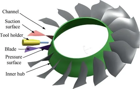
Fig. 1 Tool holder is pushed into channel of blisk.
The channel is the repeatable unit in five-axis machining of blisk. It consists of inner hub and two adjacent blades, as shown in Fig. 1. Here, the hub is a rotary surface. And the blade is composed of pressure and suction surfaces, which are often designed as free-form surfaces. To machine a prespecified point located on the surface of this channel, the tool holder is often pushed deep into the channel with a shorter cutter to increase rigidity and reduce vibration. For convenience,all the surfaces associated with the channel are all called checking surface and denoted by SC(u,v)in the following part.Here,u and v are the parameters of the checking surface in the parameter domain. And the pre-specified point is denoted by PM.
To machine the point PM, the milling portion of the tool will tangent to the machining surface,as shown in Fig.2.Here,the normal vector of the machining surface at the point PMis denoted by nM. And the point O is the center of the sphere of cutter,which is considered to be a known and fixed point.For the convenience of description in the following part, a local orthogonal coordinate system O(xm,ym,zm)is set up as follows:the point O is set to the origin of the coordinates;the vector nMis set to the zmaxis; the instantaneous movement direction of the cutter at point O is set to the xmaxis.And then the ymaxis is determined by the right hand criterion.Then any tool orientation can be represented by a unique vector in the local coordinate frame.
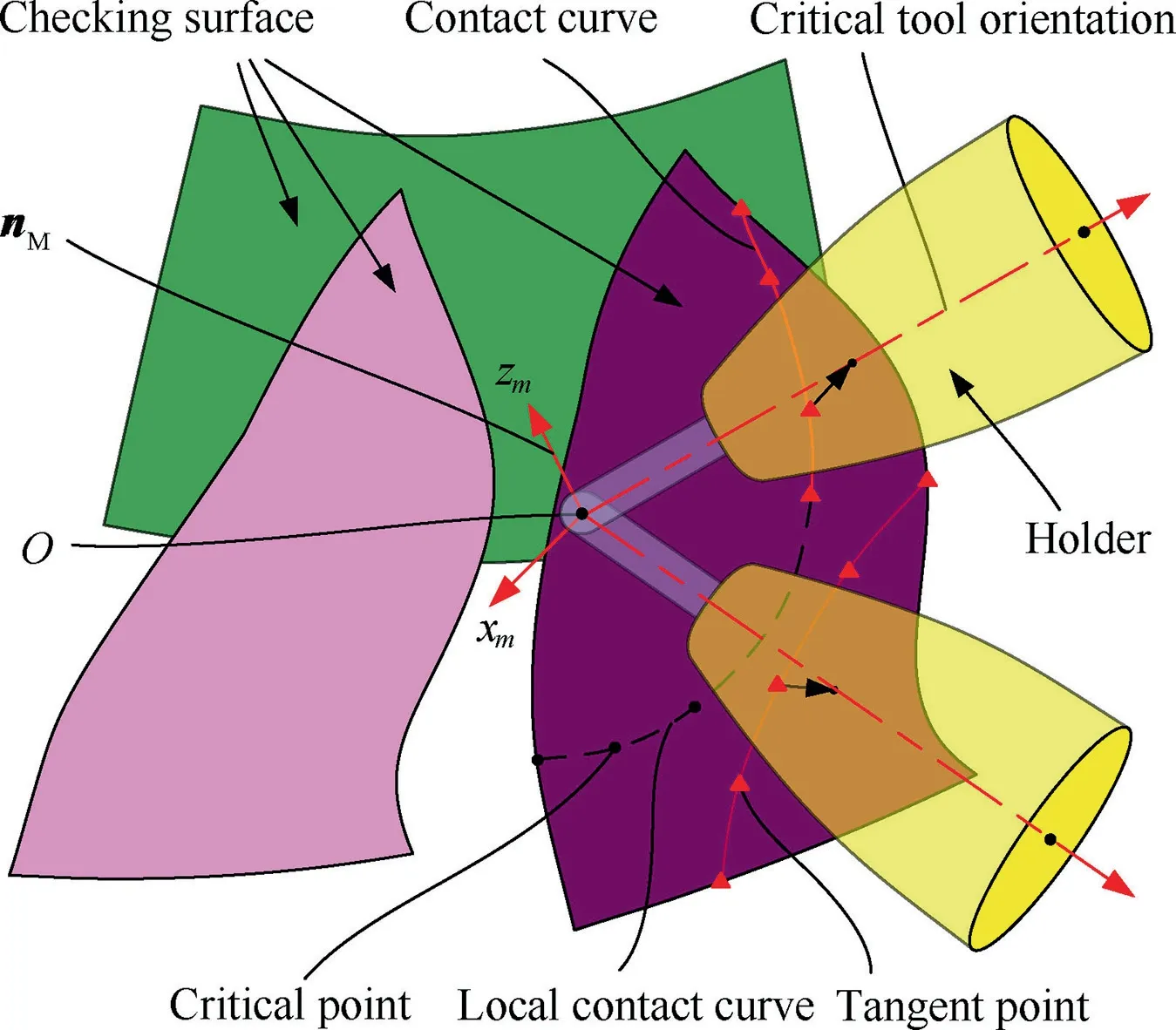
Fig. 2 Holder is in point-contact with surface.
The collision-free region is a set of tool orientations along which the tool holder will not collide with all the checking surfaces associated with the channel. Among these tool orientations, there is a special class along which the holder is in point-contact with the surface, as shown in Fig. 2. It reflects the geometric relationship between the holder and the surface.Geometrically,the boundaries of the collision-free regions can be determined by these critical tool orientations. Here, the point at which the holder is in point-contacts with the checking surface is called the tangent point. And the piecewise curves with all tangent points connected in order are called contact curves of the checking surfaces. Obviously, the tangent points on checking surfaces correspond to those critical tool orientations one-to-one. Therefore, the problem of calculating collision-free regions of holder in five-axis machining of blisk resorts to solving these contact curves.
Then the problem of solving contact curves can be further transformed into find the local contact curves of all checking surfaces. Suppose that the whole of the tool with the holder is abstracted as a ray.And the geometric relationship between the ray and the checking surface can be observed in a plane which passes through the cutter location point PM, as shown in Fig. 3. The tool holder along the tool orientation similar to lR3will not collide with the checking surface. And there is collision between the holder and the checking surface when the tool orientation similar to lR1. While the holder is in point-contact with the checking surface when the tool orientation similar to lR2.And the point Pais the tangent point.However,the tangent point will inner the checking surface or on the edge of that.Besides,in a very small neighborhood δP,the ray lR2is tangent to the checking surface at the point Pb.It means that the holder locally point-contact with the surface at that point. Then the point Pbis named the critical point. And the piecewise curves with all the critical points connected in order are called local contact curves of the checking surface. Obviously, the tangent point is a special case of the critical point,and the discontinuous contact curves are part of the local contact curves,as shown in Fig.2.Besides,the region correspond to the local contact curve is defined as a local collision-free region, which will be discussed in detail in Section 5. And the collision-free region should be the overlap of these local collision-free regions.
The local contact curve is a specific curve on the checking surface,and it can be represented by a certain number of sample critical points. And those critical points can be solved one by one with a search process.The keys of that are how to identify whether a point on checking surface is a critical point,and how to find the adjacent sample critical point. Here, the first one will be discussed in detail in Section 3, while the other one will be described in detail in Section 4.
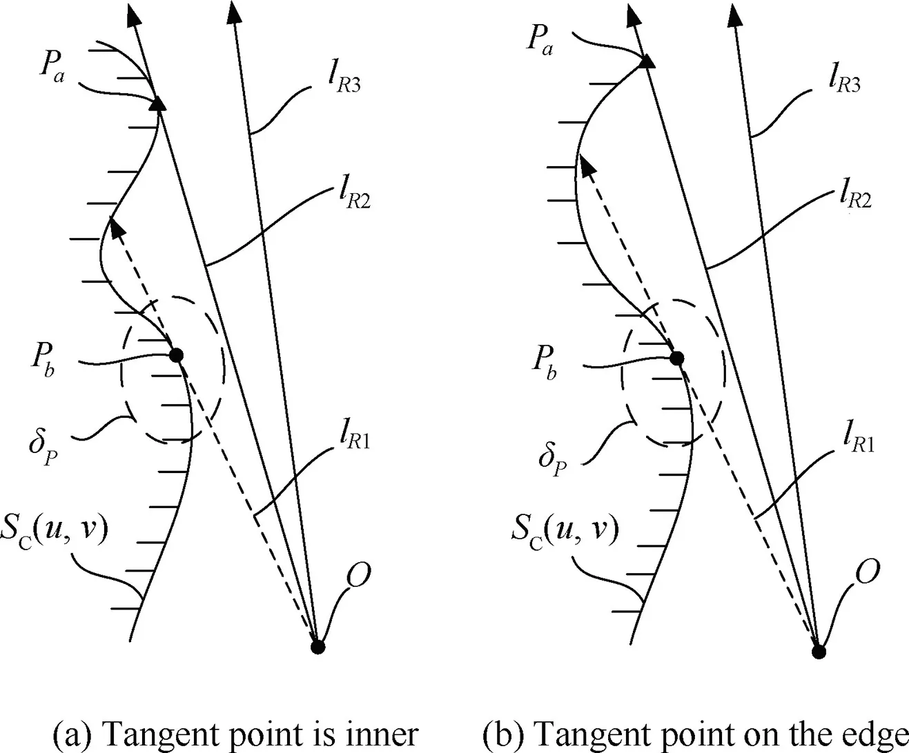
Fig. 3 Relationship between tool and checking surface.
3. Critical points on checking surface
3.1. Model of tool holder
The tool model of ball end mill with holder is shown in Fig.4.Here,the milling portion of the tool is a sphere with the radius r and the center of point O.And the tool holder is a rotary surface with generatrix of h=g(R),which is a simplified curve of actual shape and introduces the safety allowance of Δs. The parameter Δs includes the process allowance and safety clearance. Where, R is the distance from the point P on the holder to the tool axis,and h is the parameter of height of the point P along the tool axis.The vector nPis the normal vector of rotary surface at point P.Besides,the point A is the lower endpoint of the generatrix. And the parameter hAis a fixed value and depends on actual needs.Besides,the point C is the lower endpoint of the generatrix of real shape of the holder.
In this paper,the generatrix of holder is simplified into two segments, which are composed of arcs and simple function of h=f(R),as shown in Fig.4.Where,the function h=f(R)can be a combination of simple curves,such as a line,an arc and so on.It depends on the actual shape of holder.And it should satisfy the conditions shown in Eq. (1).

Here,f(R)’and f(R)’’are the first derivative and the second derivative of the function f(R), respectively.
Besides, the radius of the arc is equal to Δs, and the center of the circle is point C. And the parameters of the parabola function should make the parabola as close to the actual shape as possible with a minimum allowance of Δs.Besides, the tangent point of the parabola and the arc is denoted as B. Thus the function of the generatrix can be expressed as

where, the values of RAand hA,RBand hB, RCand hCare the parameters of the points of A, B and C.
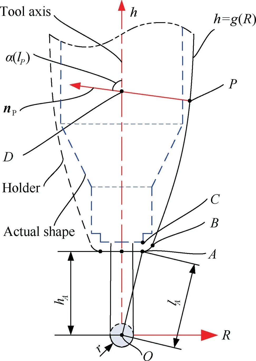
Fig. 4 Tool model of ball end mill with holder.
Then geometric parameters of the holder at the point P can be calculated. The distance between the points P and O is denoted by lP. For a given value lP, the position of point P on the generatrix can be determined according to Eq. (3).

where, lAis the distance between the points A and O.
Further, the angle between the tool axis and the normal vector nPcan be expressed as a function of α(lP). And the distance between the points P and D can also be expressed as a function of d(lP).Here,the point D is the intersection between the tool axis and the normal line of rotary surface at point P.Then the two parameters of α(lP) and d(lP) can be calculated with Eq. (4).

Here, g(R)’ is the first derivative of the function g(R).
3.2. Critical points inner the checking surface
The critical point is a reflection of a special geometric relationship between the tool holder and the surface, at where they locally tangent to each other. However, it is divided into two different cases. Firstly, the critical point is inner the checking surface, which means that the normal vectors at that point of the holder and checking surfaces are in the same direction.Secondly, the critical point is on the edge of the checking surface.In this part,the identification method of the first one will be discussed in detail.
Assume that any point inner the checking surface is a critical point, which is also on the holder. Then the tool orientation can be calculated geometrically, which in turn determines whether the assumption about that point is correct.The point on the checking surface is denoted by S(u,v). And the unit normal vectors of the checking surface at the point S(u,v) is denoted by n(u,v). Besides, the critical vector is denoted by τ(u,v), which is used to represent the tool orientation,as shown in Fig.5.According to the tangent characteristics of the two surfaces,the vectors of nPand n(u,v)must be in the same direction. So the vector n(u,v) should point to the axial of the tool according to the characteristics of the rotary surface. Where, the vector n(u,v) can be calculated by
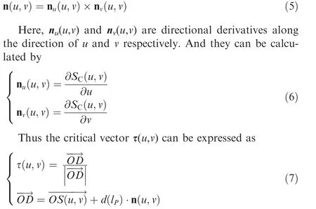
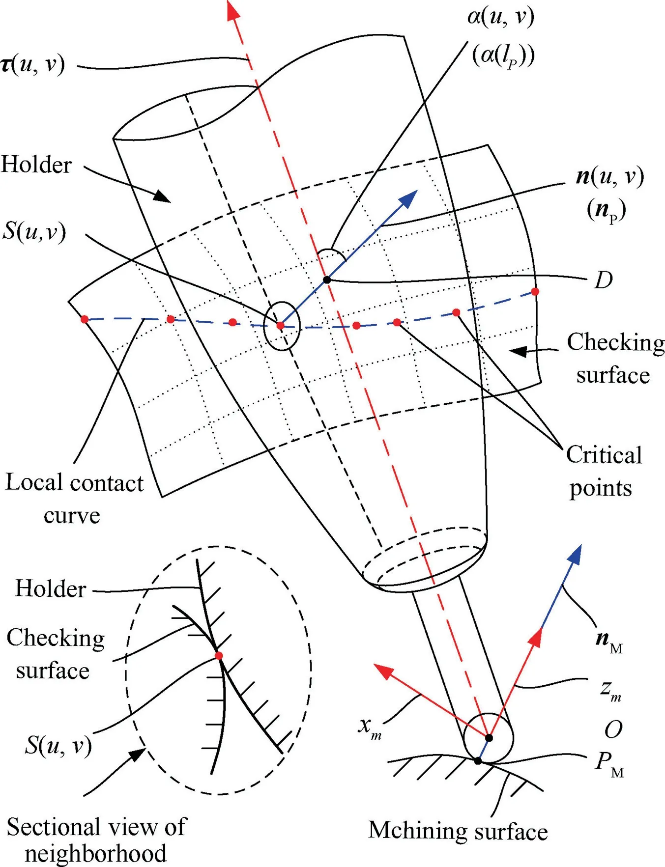
Fig. 5 Tool holder locally point-contact with surface.
where,the distance lPfrom the point O to the point S(u,v)can be calculated by Eq. (8).And the value d(lP)can be calculated by Eq. (4) with the parameter lP.

Then a function D(u,v) is constructed to describe the relationship between the holder and the checking surface at the neighborhood around a point, as

where,the u and v are the parameters of the point,while the α(u,v)is the angle between the normal vector n(u,v)and the critical vector τ(u,v). And the parameter α(lP) can be calculated with the Eq. (4), which depends on the value of d(lP).
Obviously, the parameters of u and v of any critical point inner the checking surface should make the function D(u,v)=0. That is because the angle α(u,v) describes the angle α(lP) in terms of geometric constraints, and these two angles are the same as each other.Furthermore,the process of finding the critical points inner the checking surface is equivalent to finding the parameters of those point that make the function D(u,v)=0.
In addition, it can be known from the function that the position of the critical points on the local contact curves changes continuously and there is no mutation.First,the subfunction of function D(u,v) a simple cosine function, which is continuous and has no mutations. Second, the variables α(u,v) and α(lP) of the cosine function are continuous and has no mutations. Both of them depend on the position of the point on the checking surface. While the positions of all points on the free-form surface and the normal vectors n(u,v) at those points are continuously and without abrupt change, both in the parameter domain and in physical space.Thus the distance lPfrom the point on free-form the surface to the fixed point O has the same characteristic. So the parameters α(lP) and d(lP)are continuously and without mutation,which can be obtained from Eq.(3).While,the α(u,v)is the angle between the vector n(u,v)and τ(u,v).And the vector τ(u,v)is continuously and without mutation, which can be obtained from Eq. (7). Thus the α(u,v) is also continuous without mutation.
Moreover, the continuous function D(u,v), its root D(u,v)=0 is a continuous curve in the parameter domain of the checking surface.This can be proved logically.First,the value of the function D(u,v) is represented by w. Then in the threedimensional space with the parameters u,v and w,the function D(u,v) is a continuous surface without mutation. Thus the roots of the function D(u,v)=0 are the points on the intersection curves between the surface and the plane w=0 if they exist. And those curves may be closed or open in the region of 0 ≤u ≤1 and 0 ≤v ≤1. Obviously, the coordinate values of that roots are orderly, continuous and without mutation.At the same time, they are also the coordinates of the critical points in the parameter domain of checking surface. So the local critical curve with the critical points connected in order is also ordered, continuous, and without mutation.
3.3. Critical points on the edge of checking surface
The geometric relationship between the holder and the edge of the checking surface is different from that between the holder and the surface. The former does not require that the normal vectors of the two surfaces at the same point are in the same direction. It is the degradation of two surfaces locally tangent to each other.Then the edge can be considered as the center of a special tubular surface with a radius of zero. The critical points on this particular surface coincide with the edge. Thus the edge is a special local contact curve of the checking surface,and any point on it is the critical point.The calculation of corresponding critical vector will be described in detail in this part.
The geometric relationship between the holder and the edge at the neighborhood around a point is shown as in the Fig. 6.Here, the curve SC(u,0) is an example of the four equivalent edges of the checking surface. The point on the curve SC(u,0)is denoted as S(u,0). Besides, the tangent vector of the curve at the point S(u,0) is denoted as nu(u,0). It is a special case of the directional derivative nu(u,v) of the checking surface at the point S(u,0), which can be calculated by Eq. (6). The normal vector of the checking surface at the point S(u,0) is denoted as n(u,0). The vectors nu(u,0) and n(u,0) depend only on the point S(u,0). Then the critical vector τ(u,0) can be expressed as

where,the distance lPfrom the point O to the point S(u,0)can be calculated by Eq. (8). And the geometric parameter d(lP)can be calculated by substituting the value of lPinto the Eq.(4).While,the vector nPis the unit normal vector of the holder at the point S(u,0), which can be calculated geometrically.
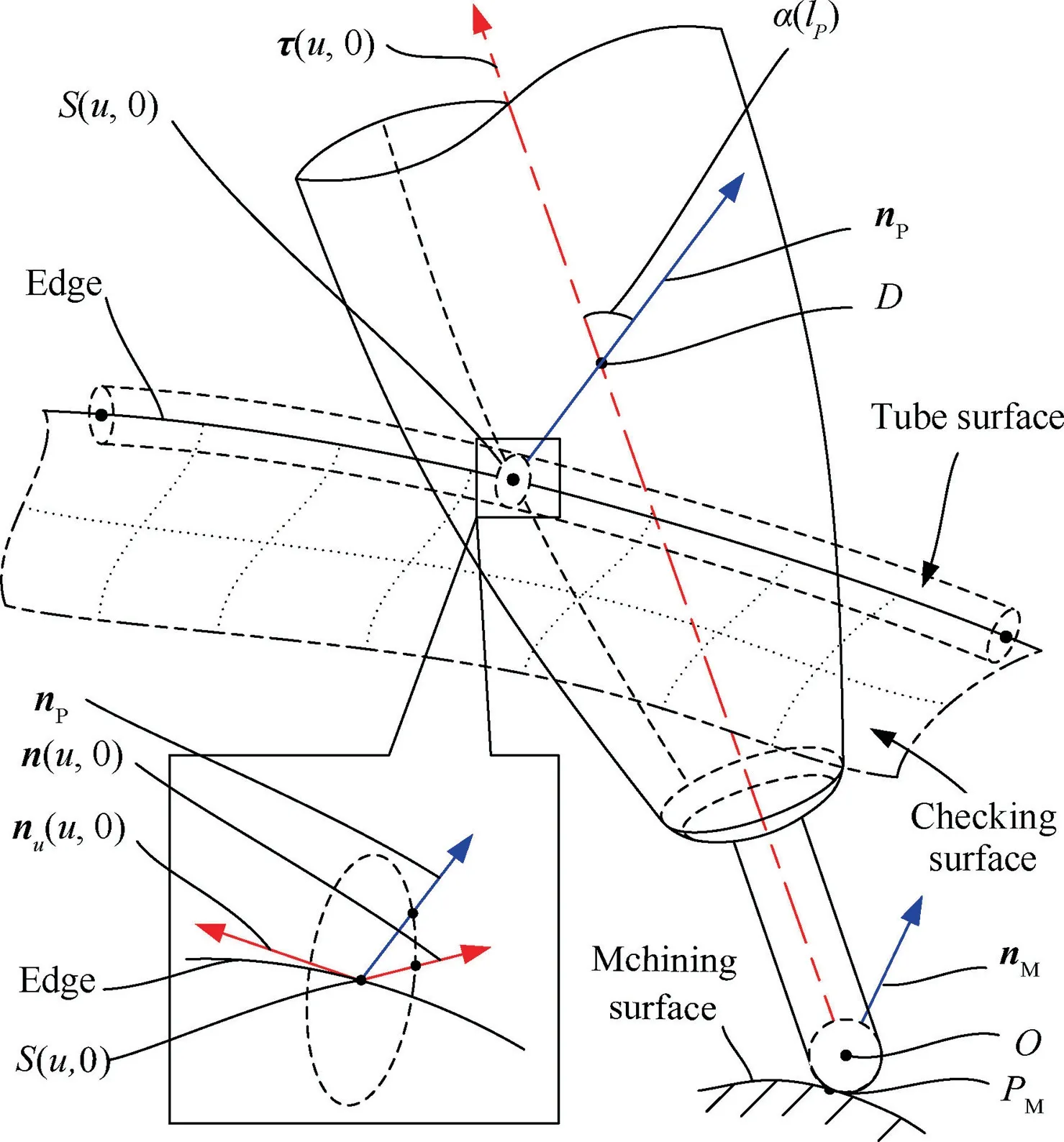
Fig. 6 Tool holder locally tangent to edge.
Since the holder is locally tangent to the edge,the vectors nPand nu(u,0) are perpendicular to each other. Besides, the vectors nu(u,0) and n(u,0) are perpendicular to each other. That can be derived from the calculation of vector n(u,0), as shown in Eq. (5). Then the two vectors n(u,0) and nPare in a plane perpendicular to the vector nu(u,0).So the vector nPcan be represented as rotating the vector n(u,0) counterclockwise by an angle around the vector nu(u,0). Here, the angle is denoted by β(u,0), which -π<β(u,0)≤π. And the can be calculated by
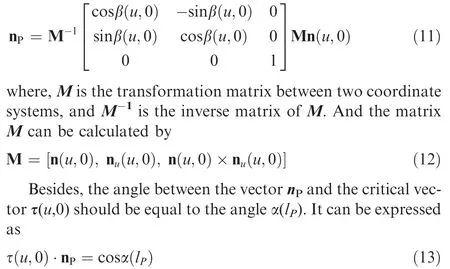
where,the geometric parameter α(lP)can be calculated by substituting the value of lPinto the Eq.(4).In addition,the direction of the critical vector τ(u,0) is the same as the direction from the point O to the point D. Then the Eq. (13) can be equivalently converted as
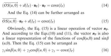
Here, the symbols γ1, γ2and γ3are constants.
Obviously,there are two solutions of β(u,0)are included in Eq.(16)for any point S(u,0).There are two vectors that correspond to the two solutions of β(u,0) are symmetric about line OS(u,0). This is because the position of holder is not completely constrained by the geometry of the curve, when they locally tangent to each other. Here, the direction to the side of channel is required. It can be identified by Eq. (17).

4. Tracking search of sample critical points
4.1. Overview of search algorithm
As described in Section 3.2, the local contact curves inner the checking surface must be smooth and continuous. And they may be closed or opened, where the endpoints of opened curves must be on the edges of checking surface, as shown in Fig.7.Where,the inhibit curve is the intersection of the checking surface with a sphere of radius lA. Here, the value lAis a fixed parameter of holder. And the center of that sphere is at point O. Then there won’t be any local contact points inside the area contained by that sphere. So,the point O’ must inner the area enclosed by the closed local contact curve if it exists.Here,the point O’ is the nearest point on the checking surface to point O.Therefor the closed local contact curves must intersect the parametric curve passing through the point O’ on the checking surface.And the checking surface can be divided into parts A and B by this parametric curve. On each part of the checking surface, there are only opened local contact curves.
The analysis in Section 3.2 shows that the local contact curves are continuous and have no mutations. As long as any point on the local contact curve is found,then the adjacent sample points can be searched one by one, as shown in the Fig. 8. And the process of searching all sample critical points on each part of the checking surface is divided into two steps,as described below.
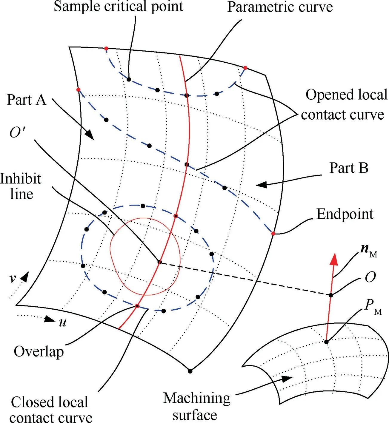
Fig. 7 Local contact curves on checking surface.
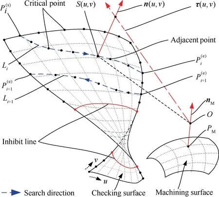
Fig. 8 Process of searching critical points on each part of checking surface.
During the process, the angle between the adjacent critical vectors can be controlled properly by discrete precision and deviation, which are represented by θδand δ, respectively.Here,the θδrepresents the ideal angle between adjacent critical vectors,while the δ represents the deviation between the actual angle and the ideal one. The value of δ reflects the stability of search accuracy. Therefore, the maximum allowable value of deviation is denoted by [δ].
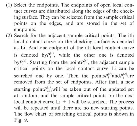
4.2. Select endpoints from critical points
The endpoints of local contact curve are distrusted independently on the edges of checking surface if they exist. They are the special critical points on the edges of checking surface,which are also on the local contact curve. It means that the both the normal vector of the holder and the checking surface at that point is coincident with each other.This is the criterion for identifying whether a critical point is an endpoint. Based on this, the normal vectors of the holder corresponding at the critical points on the edge are solved first,and then the endpoints of the local contact curves can be selected from those sample critical points.
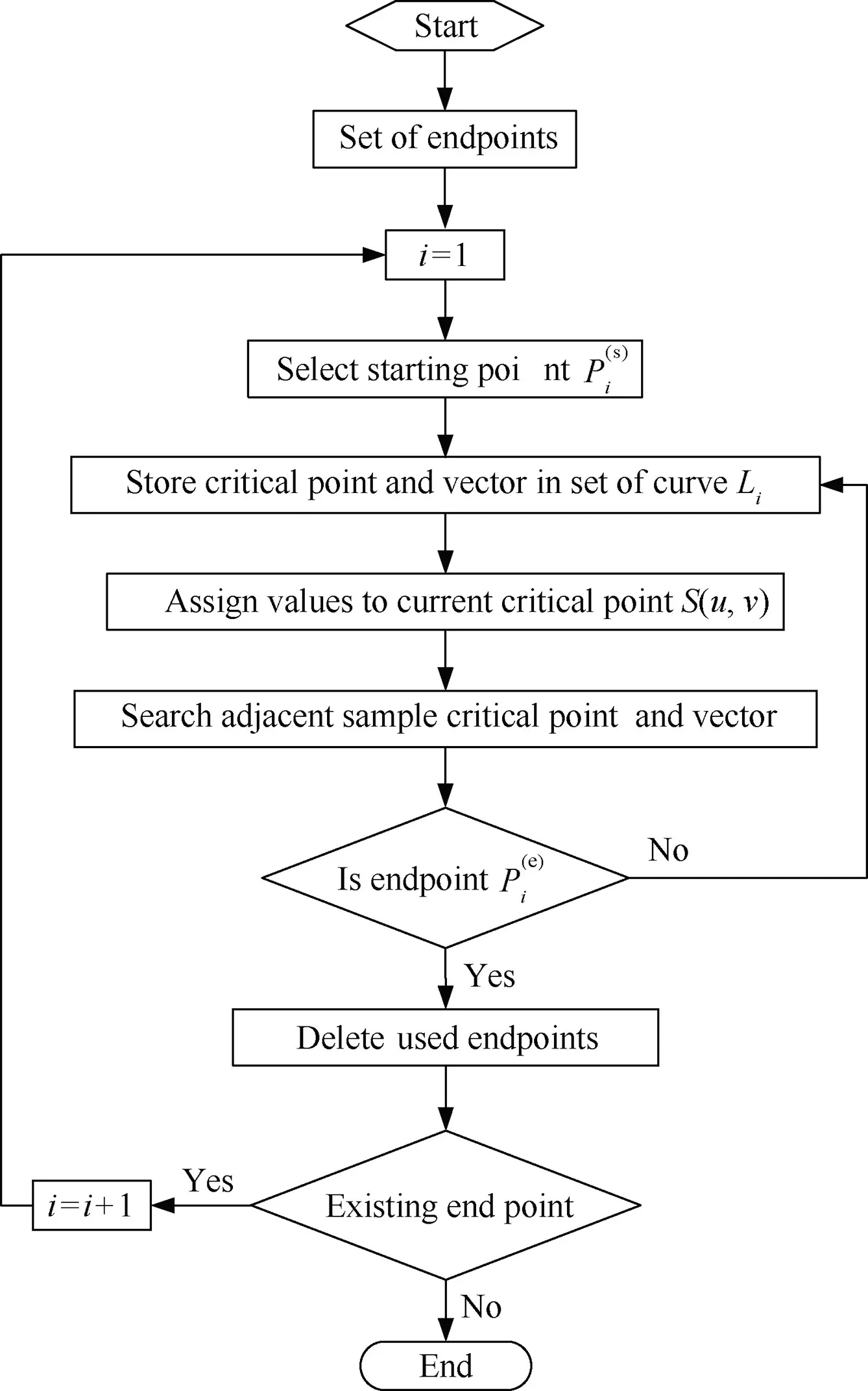
Fig. 9 Flow chart of searching sample critical points.
Every point on the edge of the checking surface is a critical point as long as it is not in the region of inhibit curve.And the corresponding critical vector can be calculated by the Eq. (10)when the normal vector nPof the holder at that point has been calculated by the Eq. (16).However,the Eq. (16) is not a simple linear system of equations, which requires a large amount of computation to solve.
To save computational resources,the edge can be converted to a tube surface with a radius equal to Δs. To compensate, it only need to set the value Δs to zero in the model of holder in Section 3.1. The parameter of the edge is taken as the parameter u of the tube surface, while the direction of rotation around the edge is set as the direction of parameter v,as shown in Fig.10.Here,the point S(ui,0)is ith sample critical point on the edge. The vectoris the normal vector of the holder at the point S(ui,0),which is need to be calculated.And the point S(ui,v)’on the tube surface is the projection point of the critical point S(ui,0) along the vector n(i)P. So the vector n(i)Pis also the normal vector of the tube surface at the point S(ui,v)’.
Then there is only one opened local contact curve on this particular checking surface. The point on that contact curve is the projection of the critical point on the edge along the vector nP.Then the projection of one end of the edge is chosen as the endpoint of the local contact curve of the tube surface.And the corresponding critical vector can be calculated by the Eq.(10). After that, the rest critical points on the special checking surface can be solved one by one, which will be described in detail in Section 4.3. And the vectors nPis coincident with the normal of the tube surface at the searched critical point.
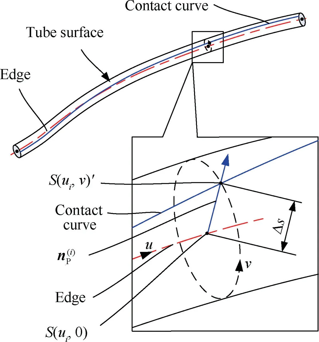
Fig. 10 Transformation from edge to tube surface.
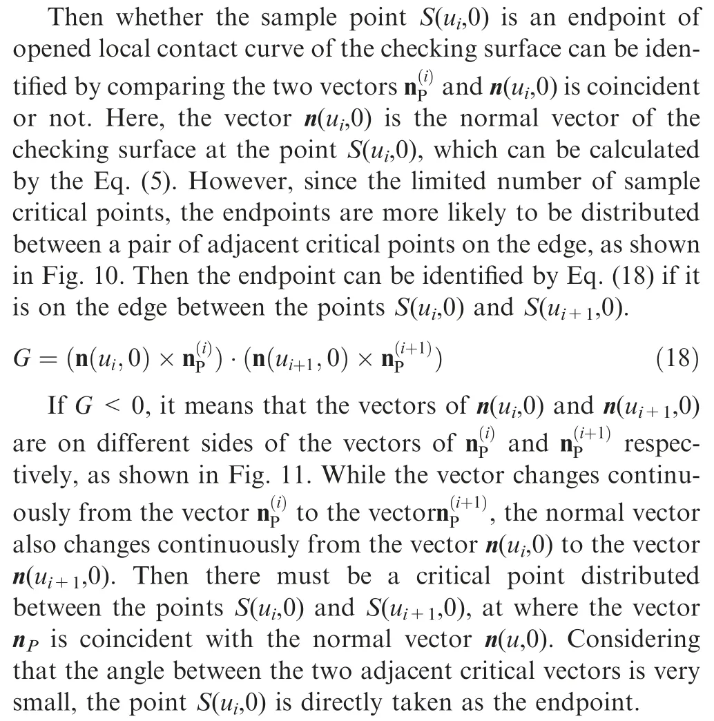
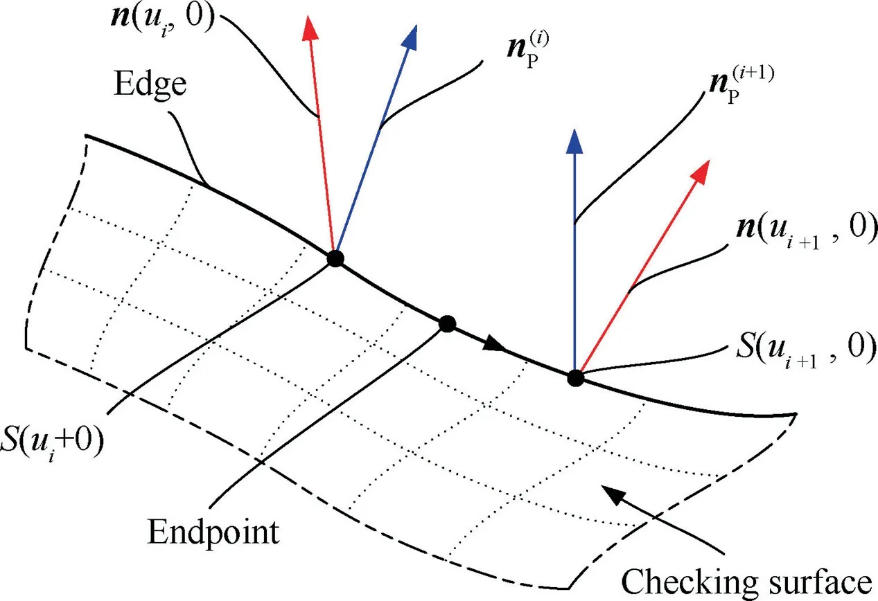
Fig. 11 Endpoint on edge between two critical points.
4.3. Search adjacent sample critical points
When the endpoints have been selected,the adjacent points on the local contact curves can be searched and the corresponding critical vectors will be calculated at the same time. For convenience, the current critical point on the local contact curve is denoted by S(uC,vC). Here, uCand vCare parameters of the point S(uC,vC)on the checking surface.Similarly, the adjacent critical point is denoted by S(uN,vN). Accordingly, the corresponding critical vectors are represented by τ(uC,vC) and τ(uN,vN) respectively. The angle between the two adjacent critical vectors is denoted by Δθ, and Δθ ≈θδ.
The process of searching adjacent critical point along the local contact curve with a given discrete precision is divided into two steps.It firstly moves with a large step alone a certain direction to approach the desired point, and then adjusts with adaptive steps to reach the adjacent critical point.As shown in Fig. 12, starting from the current point S(uC,vC), the point S(ua,va) will be searched firstly along the search vector mawith a large step.Then the point S(ub,3,vb,3)can be find by adjusting the point S(ua,va)with adaptive steps.If the point S(ub,3,vb,3)is very close to the local contact curve, it will be regarded as the adjacent critical point S(uN,vN).
In the process of moving from the current point to the target point, the search direction and the step size need to be determined. As the analysis in Section 3.2, the function D(u,v)is continuous and has no mutations.Then expand the function D(u,v)at the critical point S(uC,vC)with a first-order Taylor series as

where, the∇Du(u ,v)and∇Dv(u ,v)are the components of the gradient in the directions of u and v, which can be calculated by Eq. (20).
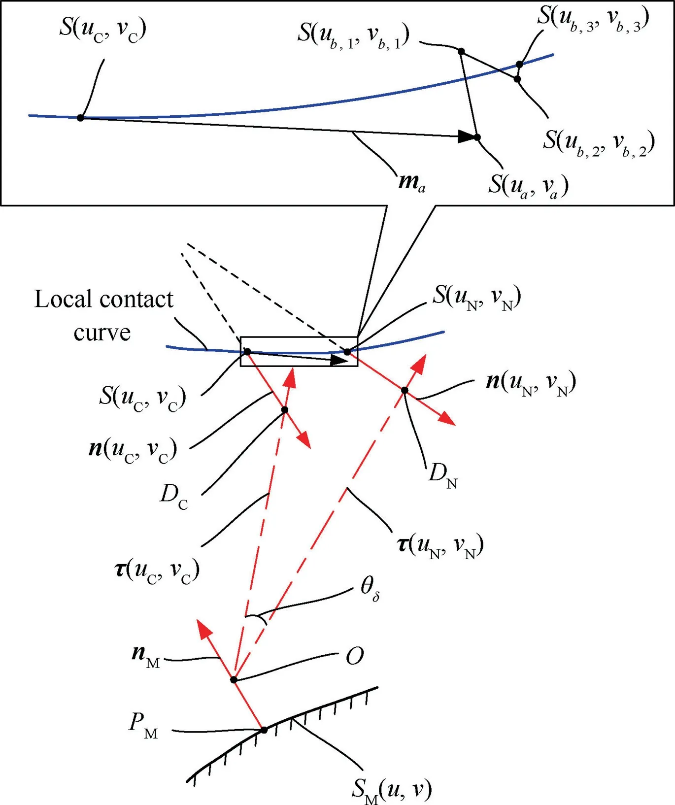
Fig. 12 Search adjacent critical point.
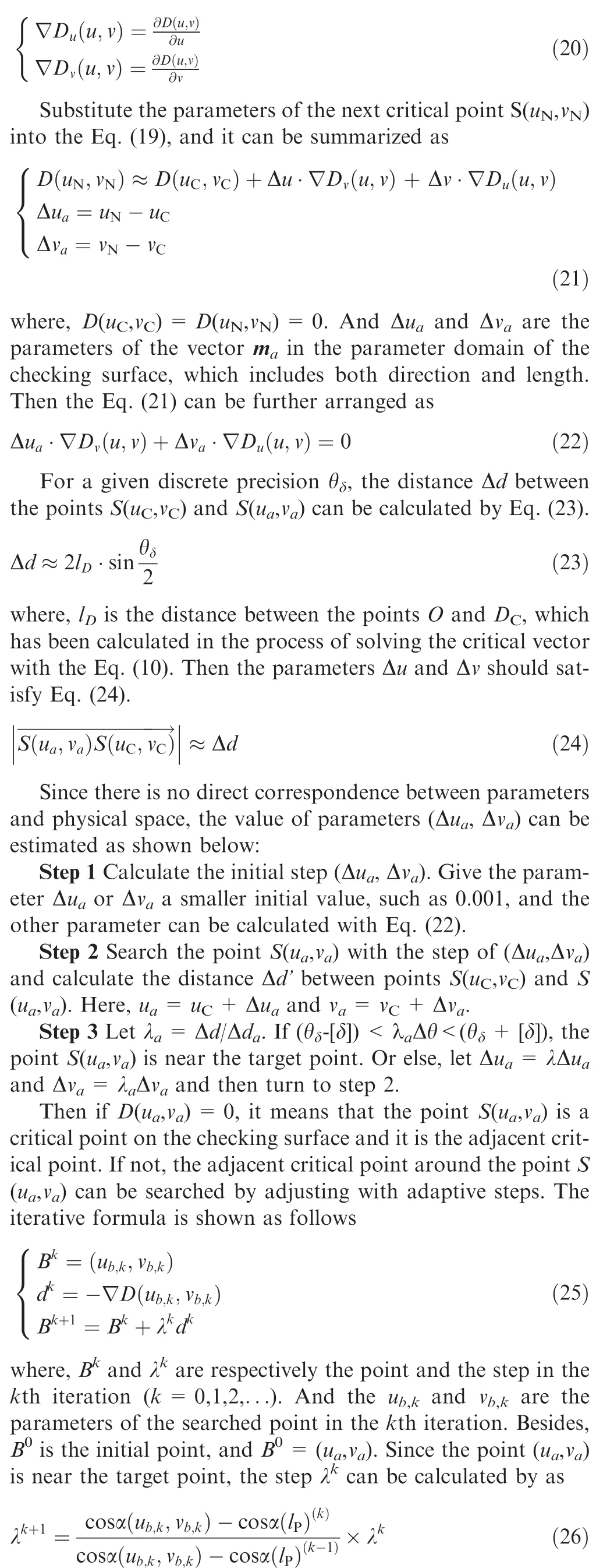
where,α(lP)(k)is the angle α(lP)in the kth iteration.Besides,the initial step λ0should be a smaller value,like 0.001,to avoid the critical point on the other local contact curve being searched.The criterion for jumping out of the iterative search is as follows

where, the symbol [ε] is the acceptable deviation, which represents the maximum distance deviation between the tool holder and the checking surface.
5. Construct collision-free regions
The collision-free region for holder is a set of tool orientations along which the tool holder will not collide with the all checking surfaces associated with the channel of blisk.It is the overlap part of the local collision-free regions of all checking surfaces. So the process of constructing collision-free regions is divided into two parts. First of all, the critical vector corresponding to the searched critical points will be processed to construct the local collision-free regions. Then the collisionfree region will be solved as the intersection of those local collision-free regions.
The critical vector τ can be mapped into a point with two parameters of γ and φ in the two dimensions space(2-D space)from the local orthogonal coordinate system O(xm,ym,zm), as shown in Fig. 13. Here, the parameter γ is the angle between the vector τ and the zmaxis,while the parameter φ is the angle between the xmaxis and the projection vector τ’of the vector τ on the plane of O-xmym. Besides, to avoid the local interference, the angle between tool orientation and the vector nMshall not be greater than π/2. Apparently, 0 ≤γ ≤π/2 and 0 ≤φ<2π.
Then the local collision-free regions can be constructed in 2-D space. The local collision-free region, denoted by Ωi, is determined by the curve Ciwhich is connected by the orderly mapped points associated with the ith local contact curve. It is a closed area which is surrounded by the curve Citogether with the diameters at the two ends of the curve and the arc,as shown in Fig.14(a).And the interior of the region is located to the left of the boundary when walking along the positive direction.
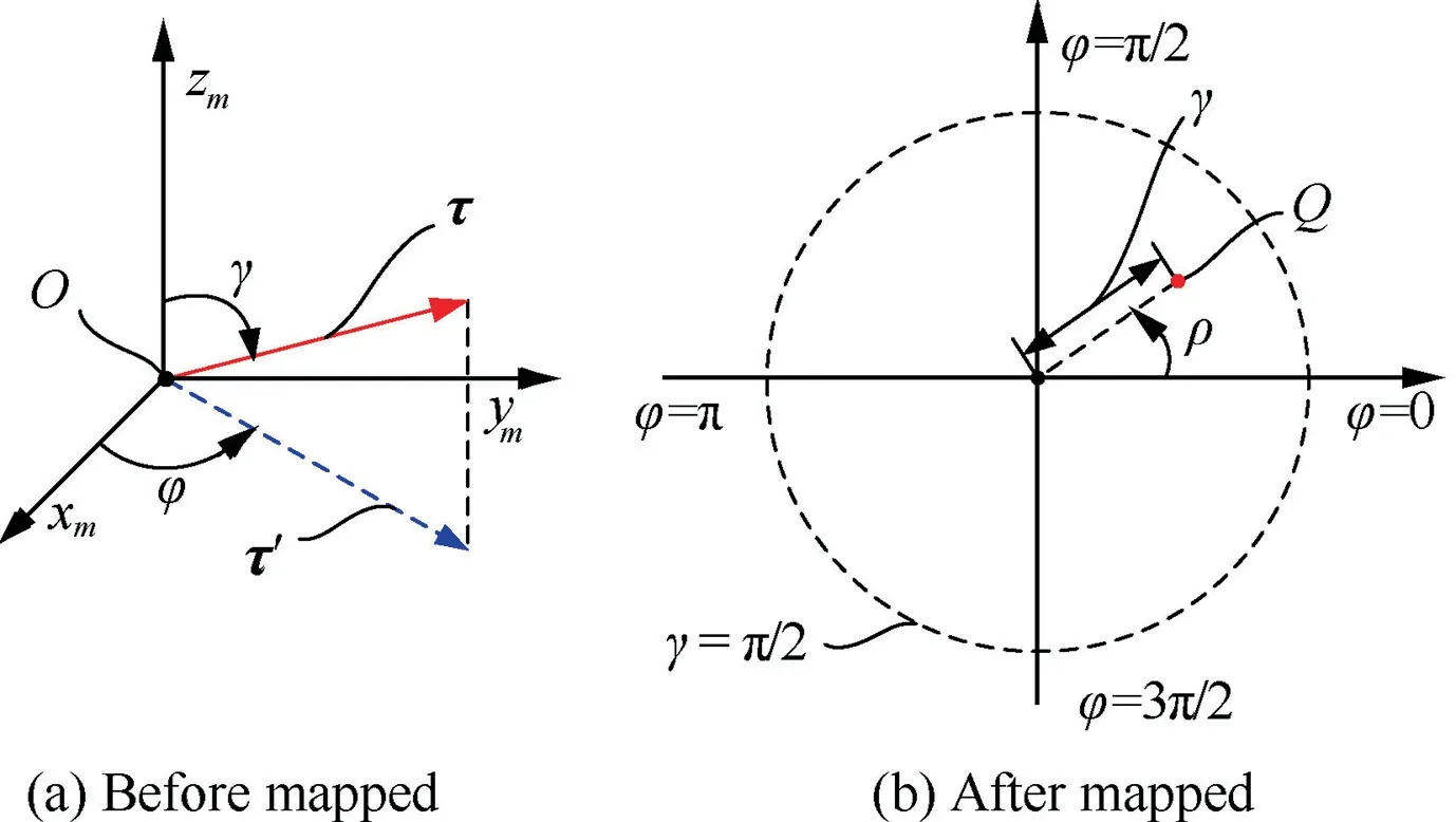
Fig. 13 Different expressions of critical vector.
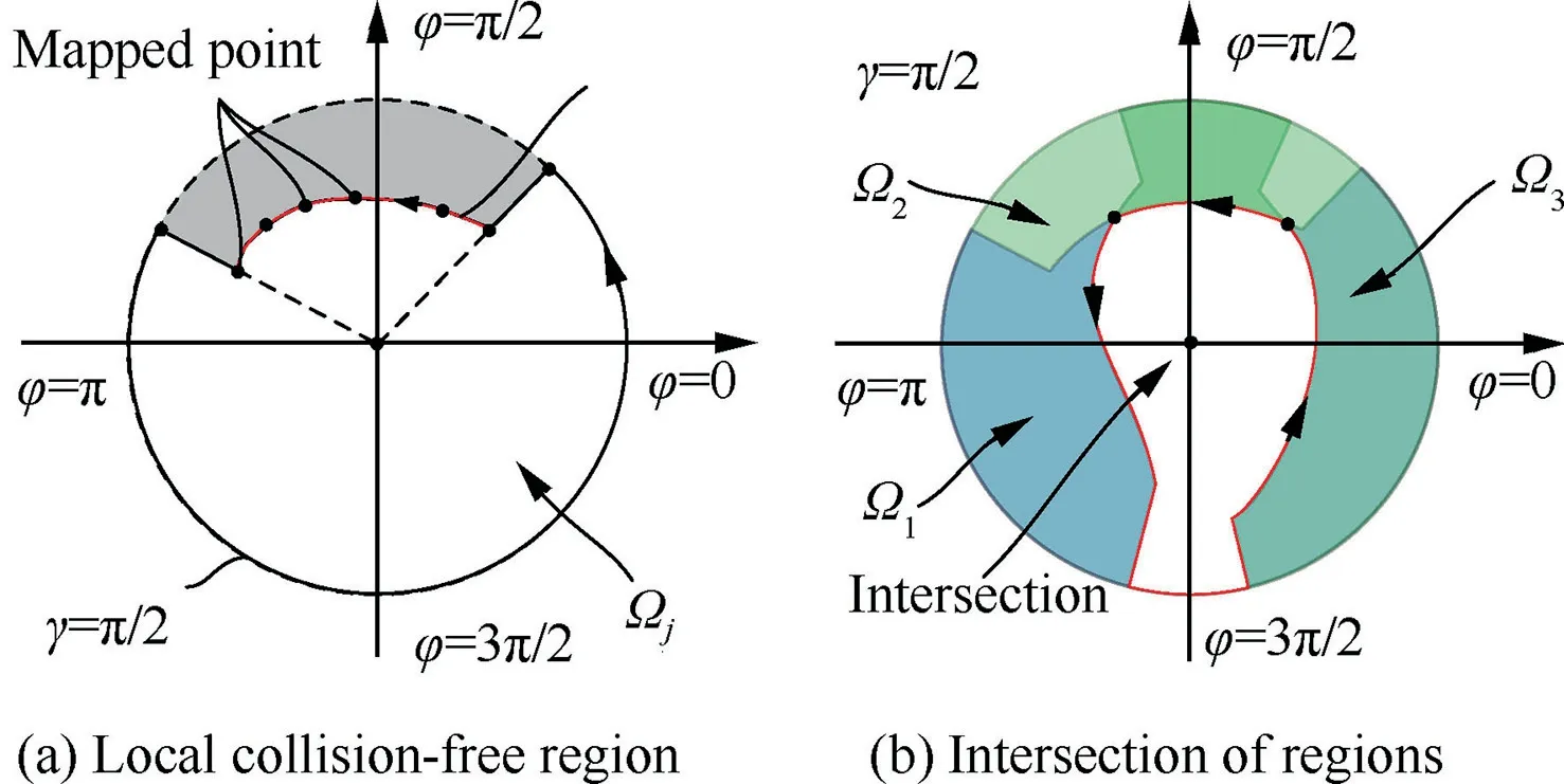
Fig. 14 Collision-free region in the 2-D space.
After that the collision-free regions associated with the channel can be constructed.It is the intersection of those local collision-free regions, as shown in Fig. 14(b). The solution to the intersection is to add local collision-free region Ωion the basis of Ω1one by one and update it. There are two keys to finding the intersection of two regions. First, calculate the intersection of the boundaries of two regions, as shown in Fig.15(a).This can be done with mature commercial software,which is not described here. Second, determine which boundary between the two intersections needs to be removed. This can be judged with a test point between two intersections on the boundary of region Ω1.If it is not inside the region Ωi,then the boundary of region Ω1that contains the test point between the two intersections needs to be removed. Otherwise, the other one should be removed. As shown in Fig. 15(a), the test point QAis outside the region Ωi,while test point QBis inside.Then the updated region Ω1is shown in Fig.15(b).It should be noted that in the case of complex constraints, the updated region Ω1may be composed of several discontinuous regions.
Besides, it is worth noting that when the local curvature of the surface at the searched critical point is too large,the holder and the checking surface will interfere. Its obvious performance is that the mapped curve Ciwill intersect itself, as shown in Fig. 16. The reason for the self-intersection is that the curvature radius Rρof the checking surface at the critical point is less than the geometric parameter d(lP) of the holder,namely Rρ-d(lP)<0.Both the values Rρand d(lP)change continuously and independently when the position of the critical point changing along the local contact curve. Then the difference between Rρand d(lP)is also continuous.So there must be two special points on the mapped curve near the selfintersecting point, at which the direction of the curve will change abruptly.30Therefor it needs to be cropped out. As shown in Fig. 16, the curve intersects itself at the point Q2,and the part of curve between the points Q2,Q3and Q4should be cropped out.
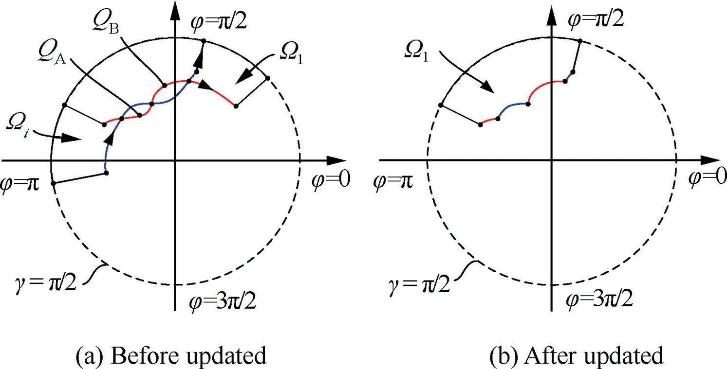
Fig. 15 Intersection of two local collision-free regions.
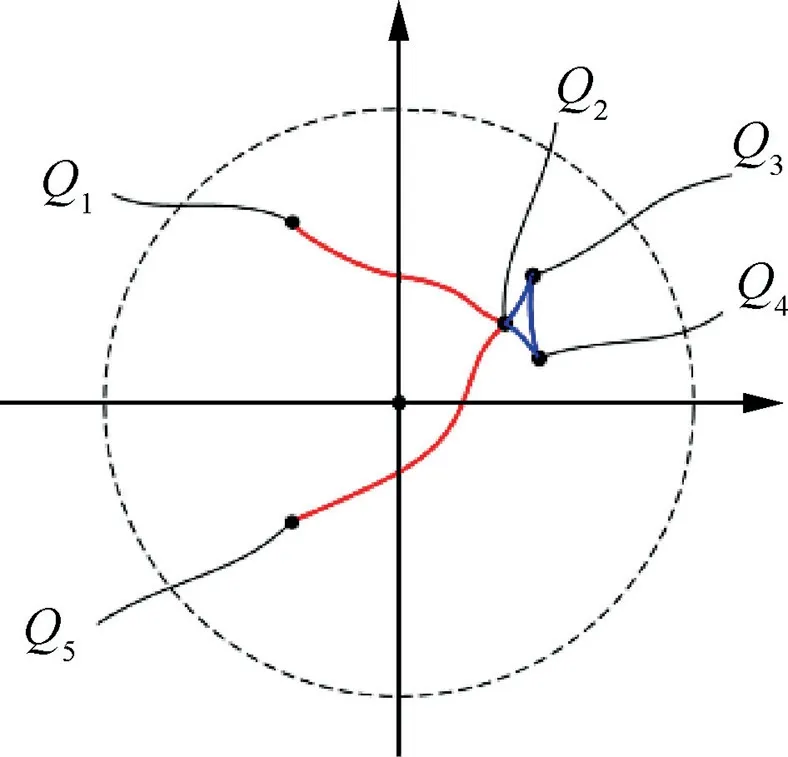
Fig. 16 Self-intersection of curve.
6. Examples
6.1. Applications
6.1.1. Applications in blisk
An opened fan blisk of aero-engine is selected to verify the correctness and effectiveness of the proposed method, and the model is similar to shown in Fig. 1.The blisk is 96.7 mm high with 34 channels. And the diameter of the outer hub is 803.3 mm, while the diameter of the inner hub varies from 477.2 to 523.2 mm. The length of the blade is about 163 mm.The milling point PMis on the inner hub surface in the channel and is close to the side of suction surface,where the constraint is more complex.
The actual shape of the holder used in applications is shown in Fig.17.It is made by Sandvik with the specification of 930-C5-P-20-15. The parameters of the cutter are r=6.0 mm and hC=70 mm. The allowance Δs is set to be 1.5 mm. This includes the process allowance 1.0 mm and safety clearance 0.5 mm.Since the channel depth is only 163 mm,only the portion of the holder within 108 mm is pushed into the channel.Then the simplified curve of the holder is as follows

Besides,the discrete precision θδ,acceptable angle deviation[δ]and acceptable distance deviation[ε]are set to be 0.1°,0.01°and 0.2 mm,respectively.The searched local contact curves on the checking surfaces are imported into the CAD/CAM software, as show in Fig. 18. The searched local contact curves are marked with notations L1-L9respectively. Where, L2and L3are the local contact curves inner the inner hub and suction surface respectively, while the rest of the local contact curves are the edges.
The critical vectors are mapped in 2-D space and drawn in(a) in Fig. 19. Here, C1-C9are the mapped curves associated with the local contact curves L1-L9in Fig. 18, respectively.The final collision-free regions of tool orientation for holder solved with the proposed method is shown in (b) in Fig. 19.And the collision-free regions of tool orientation for holder in the CAD/CAM software of UG/NX are shown in Fig. 20.It can be seen that the collision-free regions are composed of two discontinuous regions. The application of a tool orientation selected from the constructed collision-free regions in rough machining of blisk is shown in Fig. 21.
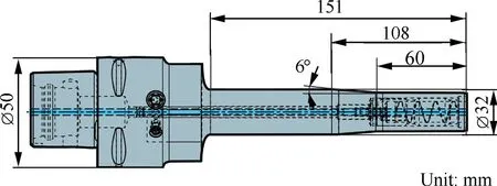
Fig. 17 Holder used in verification of blisk.
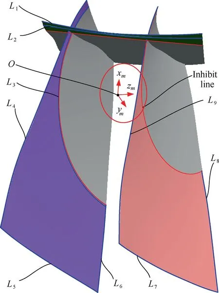
Fig. 18 Searched local contact curves in verification of blisk.
6.1.2. Applications in impeller
An impeller is conducted to verify that the proposed method could be applied to different products with different shape of holder. The impeller is 101.5 mm high with 11 channels. And the diameter of the outer hub is 303.3 mm, while the distance between the adjacent blades ranges from 14.2 mm to 23.5 mm.The milling point is on the transition surface between the blade and the hub.And the radius of curvature of the transition surface is constant 2.0 mm.The tool used in applications is shown in Fig.22.Here,the yellow part of the tool is treated as the holder. And the red part is the cutting edge of the tool,which is the sphere with radius equal to 2.0 mm.The allowance Δs is set to be 0.8 mm. This includes the process allowance 0.6 mm and safety clearance 0.2 mm.
The final collision-free region of tool orientation for holder solved with the proposed method is shown in Fig.23.And the boundaries of the collision-free regions in the CAD/CAM software of UG/NX are shown in Fig. 24. It can be seen that the collision-free region for holder is a narrow regions.
6.2. Analysis
The proposed method, which is applied in blisk, is implemented in MATLAB R2014a in a 64-bit operating system with an Intel(R) Core(TM) i5-3320 M CPU with 2.60 GHz processor. The algorithm to search critical points is the key part in the proposed method. There are 7748 points are searched in 3.36 s, which is about 46.5 % of the total running time, as shown in Table 1. The most time-consuming part is to find and calculate intersection points for all segments. In general,the time taken to compute the intersections increases rapidly as the number of critical points increases.
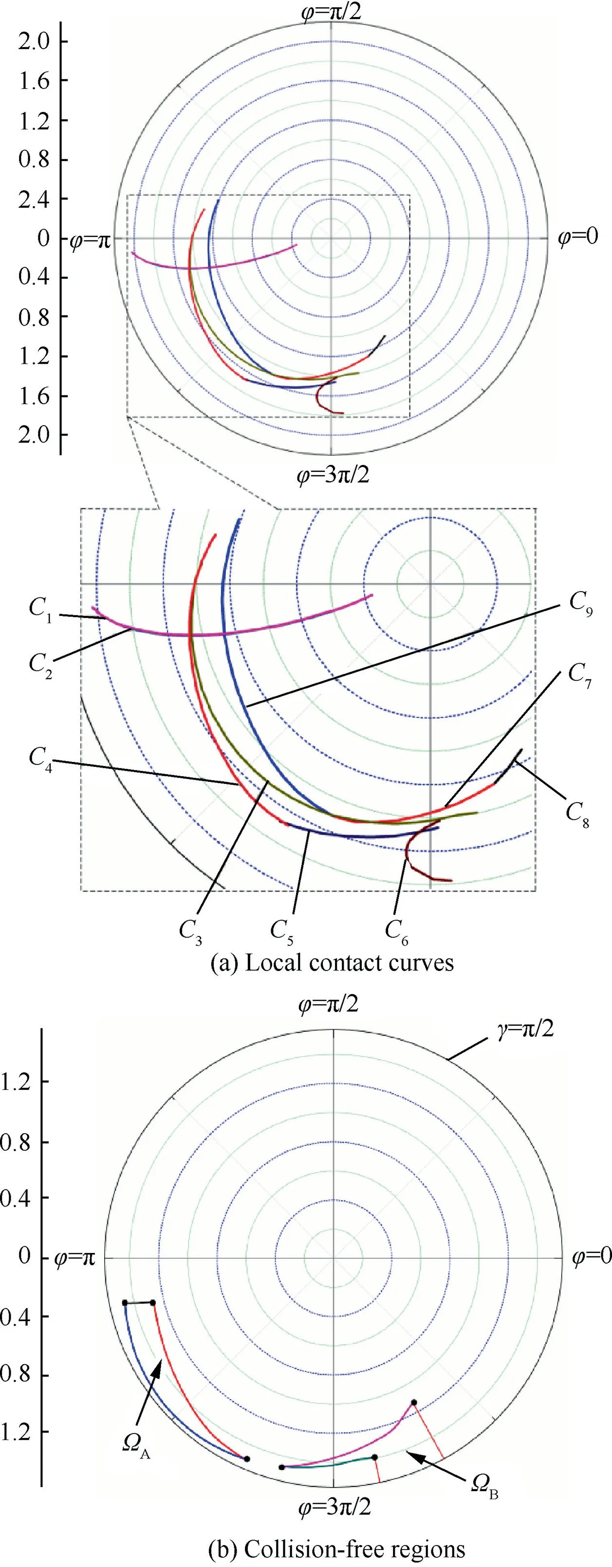
Fig. 19 Collision-free regions in verification.
The calculation errors are evaluated both in distance error ε and angle error δ. Firstly, the distance error means that the deviation between the distances from a critical point to the axis of the cutter and the theoretical distance. The mean error,maximum error, and standard deviation are 0.08 mm,0.14 mm and 0.012 mm,respectively.Secondly,the angle error means the deviation between the actual angle between adjacent critical vectors and the theoretical one. The mean error δmean,maximum error δmax,and standard deviation of error δstandare 0.0047°, 0.0098°and 0.0033°, respectively.
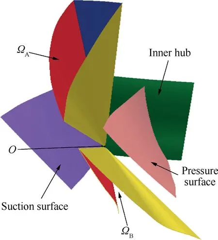
Fig. 20 Collision-free regions of blisk in UG/NX.
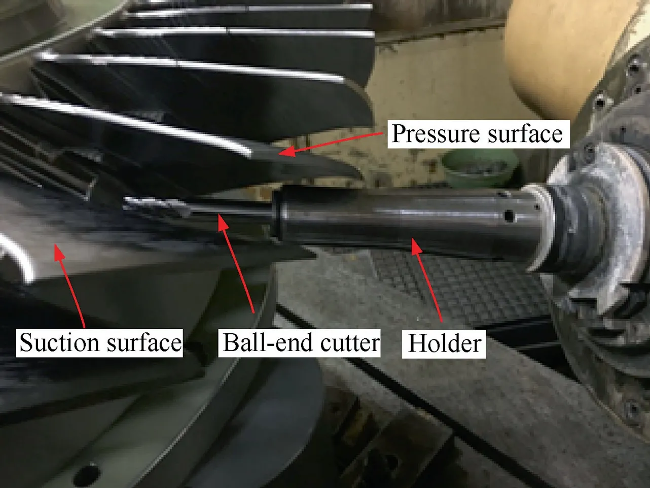
Fig. 21 The blisk is roughed on the five-axis machine.

Fig. 22 Tool and holder used in verification of impeller.
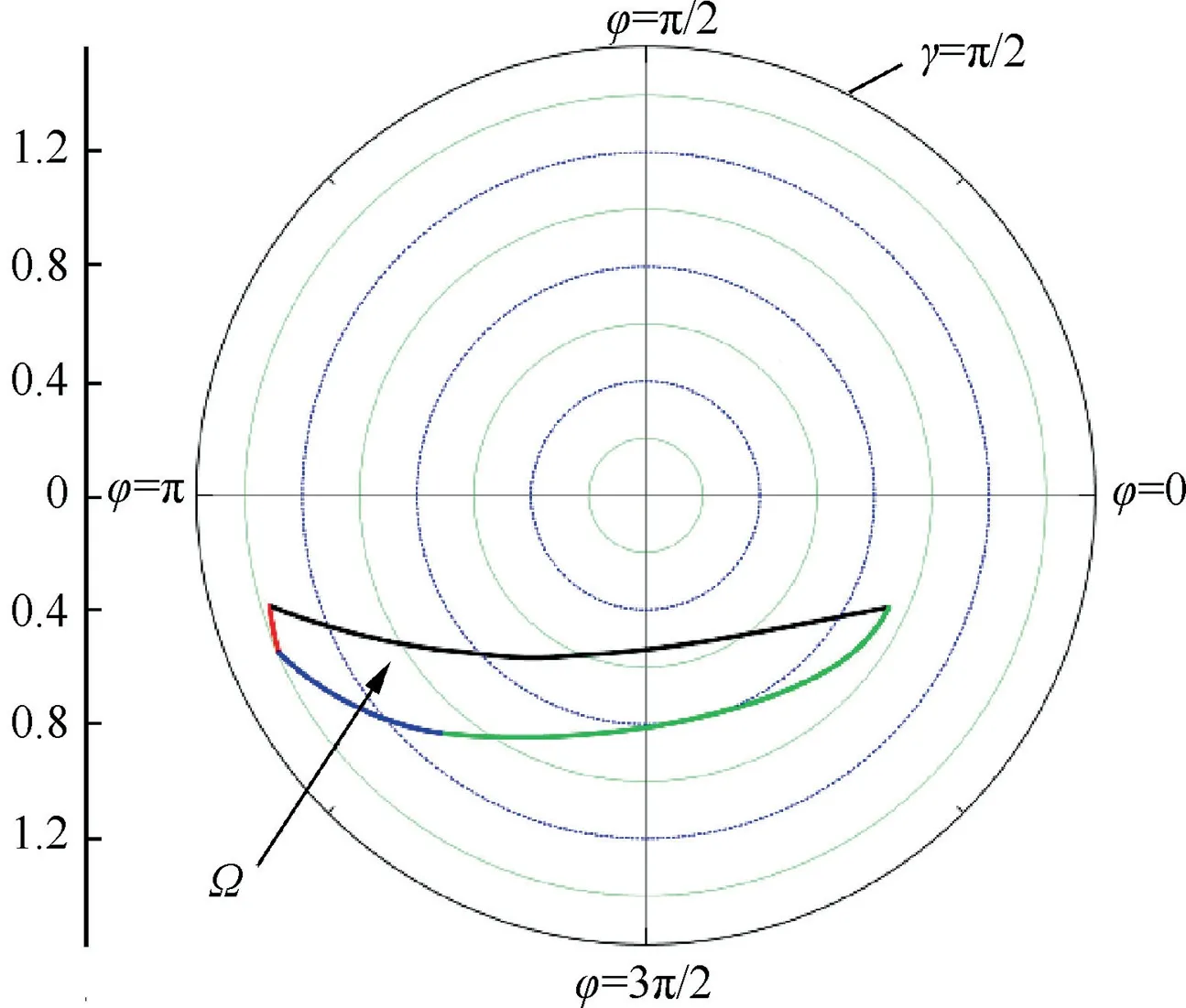
Fig. 23 Collision-free region of impeller.
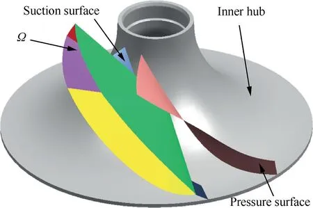
Fig. 24 Collision-free region of impeller in UG/NX.
In addition,both the searching time and the amount of critical points are related to the choice of parameters. The results of searching critical points on the local contact curve L2are used to illustrate that, as shown in Table 2. Obviously, The amount of critical points searched is directly related to the discrete precision θδ. However, the searching time is influenced significantly by both the discrete precision θδand acceptable deviation [ε]. When enlarging the acceptable deviation [ε], the maximum distance error will increase (see Table 3).
Therefore, the efficiency can be improved by simultaneously increasing the safety allowance,enlarging the acceptable deviation[ε]and reducing the discrete precision θδ.Meanwhile,as the amount of critical points is reduced,the time to find and calculate intersection points for finding the overlap of the subinterval regions will be greatly reduced. However, the only cost is a small part of collision-free region.
6.3. Comparisons and discussion
In this part,the proposed method applied in blisk will be compared with the searching critical points method in Ref. 10 and the edge detection algorithm in Ref.9.However,the method in Ref. 10 is mainly applicable to ball-end mill and hard to deal with the holder with variable radius. So, the holder is simplified as a cylinder with the constant radius of 16 mm. In the work of Ref. 9, every candidate points were first identified by collision checking between the holder and triangular facets.Then the boundaries of collision-free regions were searched by turning right when the candidate point is feasible, while turning left when not feasible.The original surfaces of blisk shown in Fig. 18 are exported into an STL (STereoLithograhpy) file as triangular facets. The number of exported facets is 35,639 when the triangle tolerance and adjacency tolerance are all set as 0.05° and 0.01 mm, respectively. The domain of (γ,φ)is divided into three levels of grids, with angle interval of 5°,0.5°, and 0.05°, respectively.
Under the condition of the roughly equal number of critical points, the results of the comparison are shown in the able 3.Here,the adjacent points are searched in a constant search step length of 0.12 mm with the method in Ref.10,while the points are searched in a constant discrete precision of angle of 0.05°between the adjacent critical vectors with the method in this paper.In the specific operation,the parameters such as the discrete precision are first set according to the proposed method in this paper, and the search parameters required in the literature are estimated according to the number of critical points searched.
From the comparison results, the efficiency of the two methods of in the Ref. 10 and in this paper is basically equal.For the same checking surfaces, the number of critical pointssearched in unit time in this paper is about 92% of the algorithm in the Ref. 10. There are two possible reasons. Firstly,the angle deviation, rather than distance deviation which is the root cause of the intervention,is used to search for critical points in this paper.Second,the constant step length is used to search the adjacent critical points in Ref. 10, and the angle between adjacent critical vectors obtained by searching is not checked and adjusted. This saves some computing resources.But the price of that is relatively poor consistency(θmax=0.092°, θmin=0.013°), which will be more significant when the machined point is close to the critical points.In fact,for different critical points on the checking surface,even in the same angle deviation conditions,the distance between the cutter and the checking surface is different. This is because the distances from the cutter location to different critical points are changed. Similarly, for the same distance deviation, the angles between different adjacent critical vectors are also inconsonant. However, with the method proposed in this paper, the two problems can be effectively controlled at the cost of less computational efficiency.

Table 1 Results of the applications of blisk.

Table 2 Results with different parameters.

Table 3 Comparisons of different methods.
In addition,it can be seen from the comparison between the method in this paper and the method in Ref. 9 that the proposed method has significantly improved the calculation efficiency. The calculation time of the method proposed in this paper is in a similar range with that of Ref. 9 at the level of angle interval of 0.5°. While, the angle interval of this paper is about 0.05°(θmax=0.056°,θmin=0.047°).Moreover,when the angle interval in Ref. 9 improved to 0.05°, the calculation time required increased dramatically since the number of potential points will increase more dramatically as the accuracy increases.This increases the time of the detecting collision and constructing the boundaries of the interference-free region. However, that is not significant in this paper, which can be verified from Table 2. This is because the relationship between the angle interval and the number of searched critical points in this paper is approximately linearly proportional,while the relationship between them is square in Ref. 9.Besides, in order to improve the accuracy, the number of exported facets also must be increased,which further increases the detection collision time for every potential point. But the theoretical surfaces are used to search for critical point in this paper,which does not increase the calculation time as the accuracy changes.
7. Conclusions
In this paper, a method of constructing collision-free regions of tool orientation for holder without interference checking is proposed. The main contributions of this work include are as follows:
(1) The work of finding collision-free regions resorts to solving the local contact curves on the checking surfaces,which further transforms into searching the critical points.
(2) A tracking-based algorithm is presented to search the critical points on the local contact curves.
(3) The searching time can be reduced significantly by selecting the suitable parameters of safety allowance,discrete precision and acceptable deviation at the only cost of small part of collision-free regions.
Declaration of Competing Interest
The authors declare that they have no known competing financial interests or personal relationships that could have appeared to influence the work reported in this paper.
Acknowledgement
This study was supported by the National Natural Science Foundation of China (No. 51675439).
 CHINESE JOURNAL OF AERONAUTICS2020年10期
- CHINESE JOURNAL OF AERONAUTICS的其它文章
- A novel surrogate modeling strategy of the mechanical properties of 3D braided composites
- A user-friendly yield criterion for metals exhibiting tension-compression asymmetry
- Aerodynamic characteristics of morphing wing with flexible leading-edge
- High cycle fatigue failure with radial cracks in gears of aero-engines
- Motion equations of hemispherical resonator and analysis of frequency split caused by slight mass non-uniformity
- Light weight optimization of stratospheric airship envelope based on reliability analysis
