Control failure of the roll-isolated inertial navigation system under large pitch angle
Jinchao SONG, Shuxing YANG, Fenfen XIONG
a School of Aerospace Engineering, Beijing Institute of Technology, Beijing 100081, China
b Xi’an Modern Control and Technology Institute, Xi’an 710065, China
c Key Laboratory of Dynamics and Control of Flight Vehicle, Ministry of Education, Beijing 100081, China
KEYWORDS Spinning vehicle;Strap-down inertial navigation system (SINS);Roll-isolated control;Control failure;Large pitch angle
Abstract Roll-isolation is an effective way for spinning vehicle to greatly reduce the roll gyro range of strapdown Inertial Navigation System (SINS) and increase the accuracy of inertial navigation.However, during a recent flight test, the roll-isolated control system failure was observed under a large pitch angle (70◦≤θ ≤85◦), which introduces a sharply increase in the roll angular velocity,the saturation of roll gyro and the inertial navigation failure. To address this issue, the governing equation of the roll-isolated system is derived with the consideration of various disturbance factors.The control failure is reproduced by numerical simulation.And the results show that the pitch and yaw angular velocity can cause a dramatic increase in roll rate under the large pitch angle,resulting in the roll-isolated control failure. Meanwhile, an improved roll-isolated control system is developed using PI controller, which is verified by mathematical simulation.
1. Introduction
A spinning vehicle spins around its longitudinal axis continuously during flight, which can reduce the impact of aerodynamic asymmetry, thrust eccentricity and other manufacturing errors, and only needs 1-2 control channels,which can simplify the control system composition.1-7Therefore, the spinning has been widely applied to miniaturized and low-cost flight vehicles.However,the continuous spinning of the vehicle with about 10 r/s, may cause problems such as increased range of the roll gyro and reduced navigation accuracy.8-12Hence, the application of the traditional strap-down inertial navigation system to the spinning vehicle is limited.To address this issue, various methods have been proposed.Imbault et al.proposed a roll-isolated strap-down inertial navigation technique with only one stable axis to isolate the continuous spinning of the vehicle,13with which the azimuth and pitch stabilized axes of the platform were eliminated based on the three-axis stabilized platform, and only the stabilization loop of roll maneuver is retained. Basically, the platform does not spin or only spins at a low roll angular velocity relative to the inertial space,in which only a stabilized axis is added based on the existing strap-down Inertial Measurement Unit(IMU).Therefore, it is also called the roll-isolated platform.13-15On one hand, as the roll-isolated platform can isolate the vehicle spinning, the measuring device is not affected by the spinning of the vehicle,which dramatically reduces the range of the roll gyro.16-18On the other hand,the roll-isolated platform can significantly reduce the navigation error caused by the scale factor error of roll gyro, and improve the observability of the system as well19
However,in a recent flight test of spinning vehicle,the control failure of the roll-isolated SINS was observed under large pitch angle,resulting in the saturation of roll gyro,as shown in Fig.1.With the increase of pitch angle(θ),especially when θ ≥70 (°)/s, the roll-isolated control begins to fail, leading to a sharp increase in the roll angular velocity p (up to 150 (°)/s),and saturation of gyro with a range of 150 (°)/s.
In recent years, there are many literatures on the rollisolated control system. Zhou et al. proposed a compensation method for roll-isolated optical fiber strap-down inertial navigation stable loop using the lead-lag network.20Later, they proposed a second-order discrete Active-Disturbance-Rejection Controller(ADRC)algorithm to effectively suppress the platform pedestal interference by employing the ADRC algorithm.21To improve the visibility and reduce alignment error, Shi et al. proposed a SINS calibration scheme for the initial position of the stationary base by changing the IMU roll angle around the roll axis based on the roll-isolated platform.20To address the issue that the slip ring is susceptible to electrical noise during transmission and then generates control errors in the harsh missile-borne environment, Liu et al. designed an active anti-rotation control method using servo motor.22Nonetheless, for almost all of the existing works, the rollisolated control failure has not been mentioned yet, and the mechanism of the roll-isolated control failure under large pitch attitude angle has not been revealed.Therefore,it is the objective of this paper to make a comprehensive analysis of the reason for the roll-isolated control failure and propose the corresponding methods to deal with it.
The remainder of this paper is organized as follows. In Section 2, the model of roll-isolated control system is established. In Section 3, mechanism analysis for the roll-isolated control failure is presented. Improved control methods roll-isolated platform are proposed and verified in Section 4. Conclusions are drawn in Section 5.
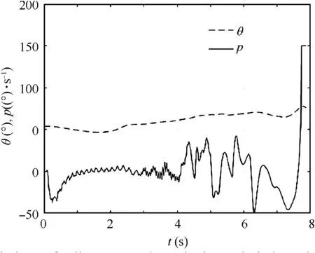
Fig. 1 Variations of roll gyro angular velocity and pitch angle with time.
2. Model of roll-isolated control system
2.1.Roll-isolated two-dimensional strap-down inertial navigation system
The roll-isolated two-dimensional Strap-down Inertial Navigation System (SINS) is originated from a three-axis stable platform with the elimination of the yaw and the pitch stable axis of the platform,and only the stabilization loop of the roll axis is retained, forming a roll-isolated platform with only one stable axis. In fact, the roll-isolated two-dimensional SINS is realized just by installing the classic SINS on the roll-isolated platform, as shown in Fig. 2.20For a roll-isolated stable platform with ideal roll-isolated support, the platform will not rotate with the spinning of carrier. However, the friction of the bearings will drive the platform to rotate with the spinning of carrier when the platform is supported by two bearings. A roll-isolated control system is constructed by means of the SINS, a torque motor and a controller to avoid the rotation of the platform. And the platform can keep stationary or spin at a very low roll rate relative to the inertial space. In some practical applications, the roll angle of the platform is used as the feedback due to the requirements on initial alignment and navigation accuracy, which indicates that the roll angle of the platform is almost zero.Therefore,the roll-isolated control system is mainly composed of PID controller, control motor, platform dynamics and SINS, as shown in Fig. 3.
2.2. Mathematical model of torque motor
Unlike the common motor position control system, the rotor of the motor fixed to the platform in the roll-isolated platform does not rotate, while the stator of the motor continuously rotates with spinning vehicle.
Fig. 4. shows an equivalent circuit diagram of the DC torque motor using the armature voltage control,where Uais the armature control voltage, Rais the armature resistance, Lais the inductance, Eais the counter electromotive force, iais the armature current, pris the angular velocity of motor output shaft relative to motor stator, TLis the torque load of motor(friction, etc.).
The stator of the spinning vehicle motor that is fixed to the vehicle continuously rotates with the vehicle. Therefore, the stator roll angular velocity is equal to the vehicle roll angular velocity pb, and the rotor roll angular velocity is equal to the platform roll angular velocity p. Then the relative roll angular velocity of the armature conductor in the stator magnetic field is
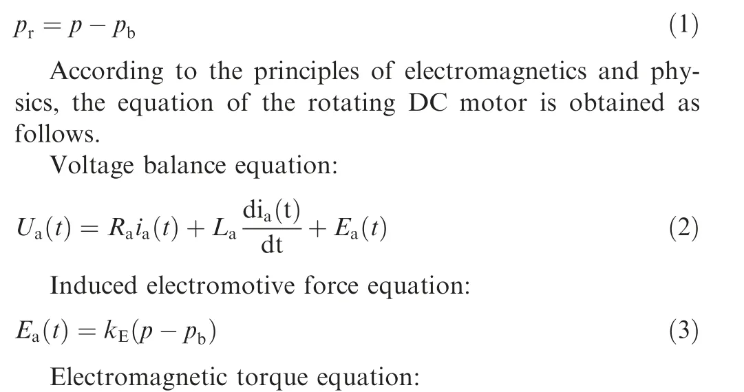
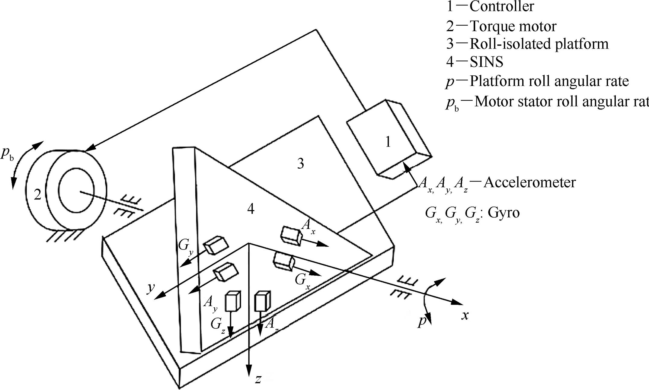
Fig. 2 Structure of roll-isolated two-dimensional SINS.

Fig. 3 Structure of roll-isolated control system.
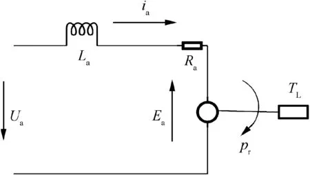
Fig. 4 Diagram of DC torque motor equivalent circuit.

where kEis the counter electromotive force coefficient and kMis the electromagnetic torque coefficient.
2.3. Model of roll-isolated platform dynamics

where J is the inertial moment equivalent to the motor shaft;TLis the torque load of motor (friction, etc.), B is the viscous damping coefficient equivalent to motor control shaft, and is often ignored.
The body coordinate system oxyz is used to describe the dynamic model of the roll-isolated platform with the righthand rule, where the coordinate origin is located at the centroid position of the vehicle, ox-axis coincides with the longitudinal axis of the vehicle, points to the direction of the nose, oy-axis is perpendicular to ox-axis in the reference plane of the vehicle and points right, oz-axis is perpendicular to oxy-plane and points down.
The three angular velocity components of the body coordinate system p,q and r are the components of the body axis system oxyz angular velocity relative to the ground (inertia)coordinate system oxgygzgrespectively. The relationship between the body coordinate system and the ground coordinate system is shown in Fig. 5.
The body coordinate system oxyz can be obtained by rotating yaw angle ψ, pitch angle θ and roll angle φ of the ground coordinate system oxgygzgin the navigation calculation. First,transition coordinate system ox′y′zgis obtained by rotating ψ around ozg-axis at the velocity of ψ·. Then, transition coordinate system oxy′z′is obtained by rotating θ around oy′-axis at the velocity of θ·.At last,the body coordinate system oxyz is obtained by rotating φ around ox-axis at the velocity of φ·,which is common in the inertia navigation system (Table 1).
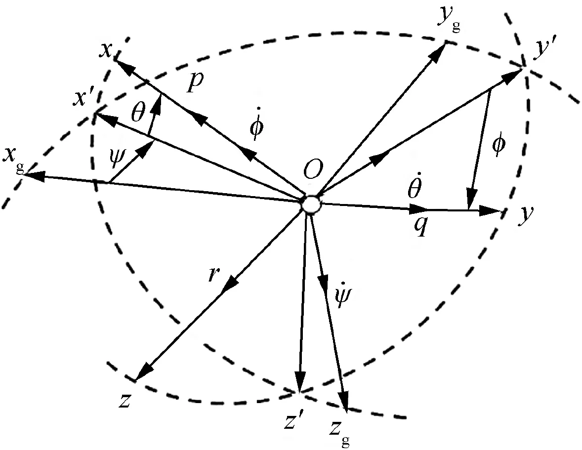
Fig. 5 Relationship between body coordinate system and ground axis system.

Table 1 Range of roll gyro needed of different pitch angle.
From Fig. 5, the relationship between the angular velocity component of the body coordinate system and the attitude angle rate can be obtained as follows.
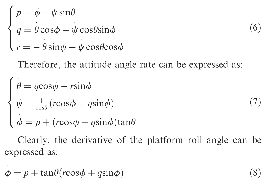
where p is the roll angular velocity of the platform/motor rotor, q and r are the gyro angular velocity along the pitch and yaw axis of platform respectively, θ is the pitch angle of vehicle and φ is the roll angle of platform. As the pitch and yaw channels of the platform are fixed to the vehicle,the pitch and yaw angular velocity of platform are equal to those of the vehicle, which can be measured by the SINS.
Denoted kr=tanθcosφ and kq=tanθsinφ respectively.Clearly, the disturbance factors krand kqvary with φ and θ,and Eq. (8) can be rewritten as:

2.4. PID control model of roll-isolated platform
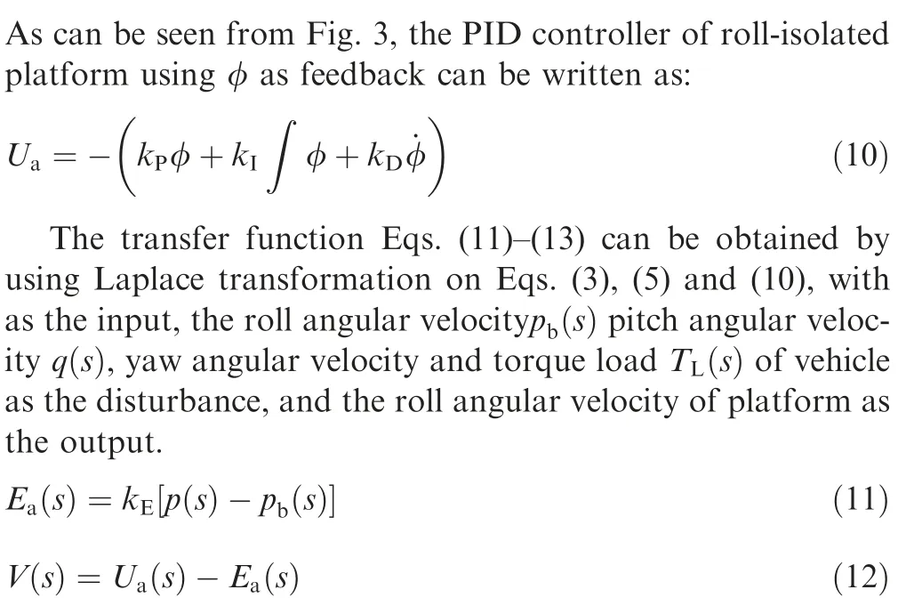
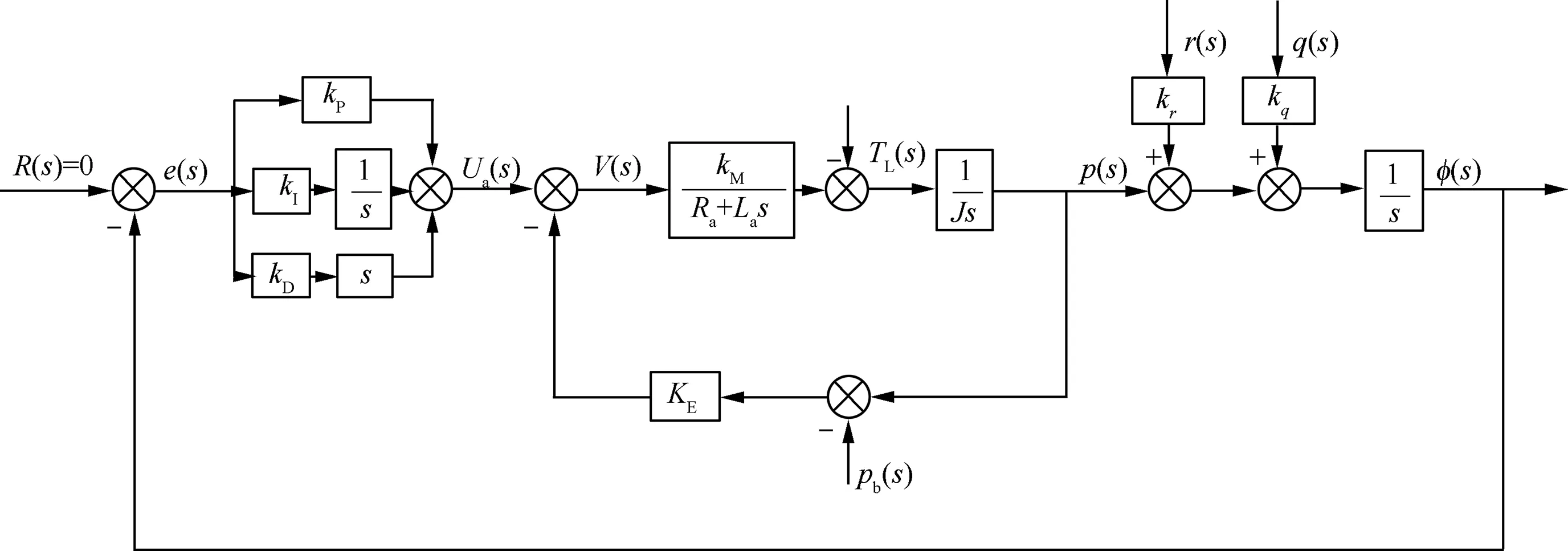
Fig. 6 Block diagram of roll-isolated PID control system.
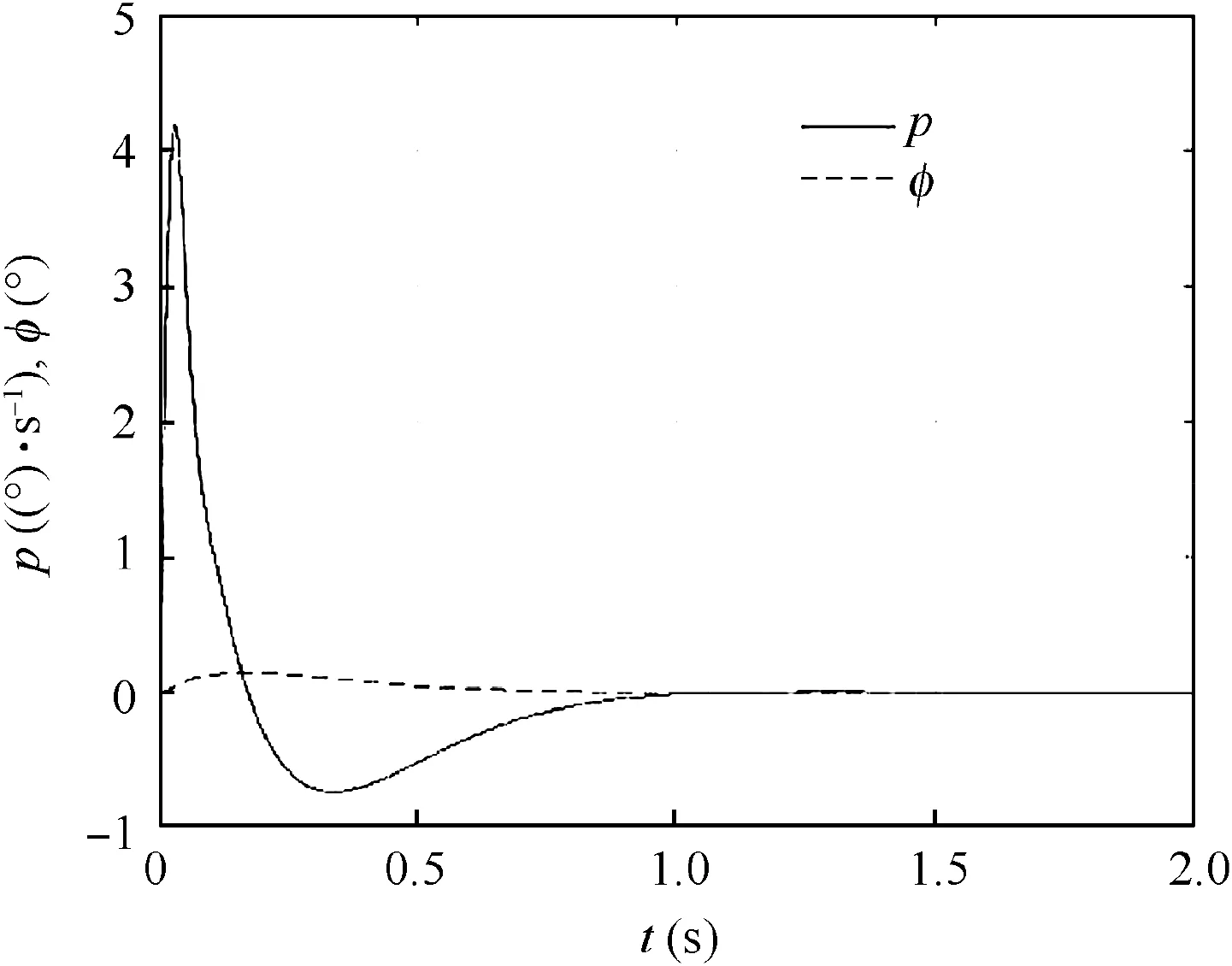
Fig. 7 Step response of roll angular velocity and roll angle of PID controller.
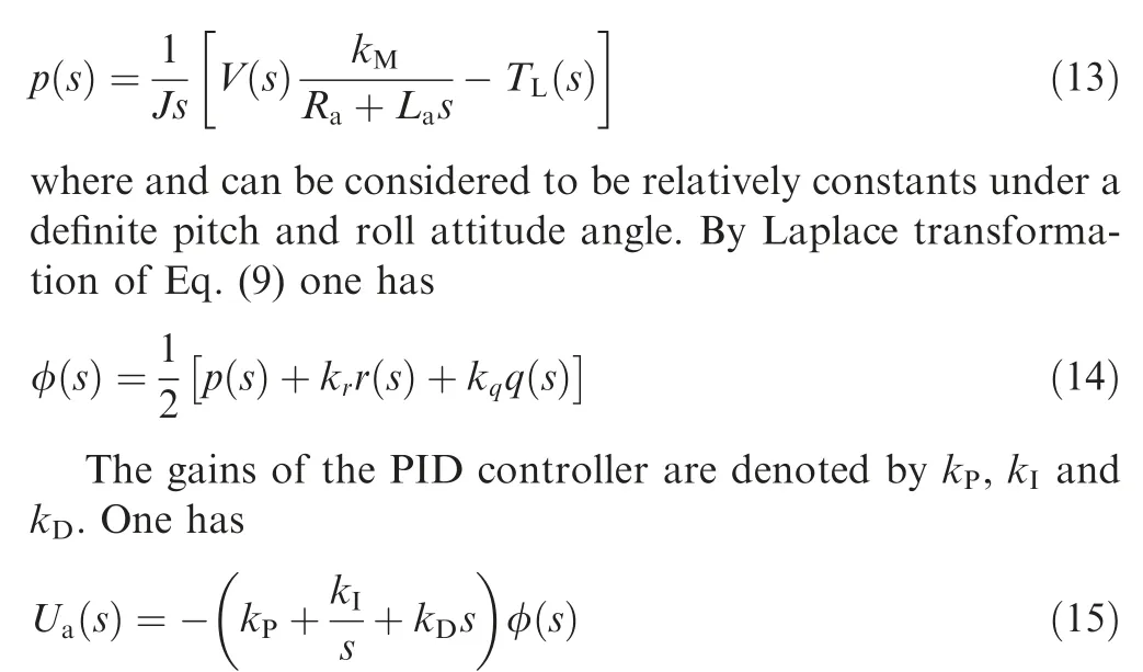
Therefore, the block diagram of the roll-isolated control system can be obtained by Eqs. (13)-(15), as shown in Fig. 6.
3. Mechanism of the roll-isolated control failure
3.1. Fault recurrence of the roll-isolated control failure
Simulation is conducted for the roll-isolated platform control system under different pitch angle based on the mathematical model established in the previous section, in which the parameters of the motor are set as Ra=0.8 Ω,La=0.0006 H, TL=0.2 N·m, kE=4.94×10⁻³V/((°)/s),kM=0.264 N·m/A, J=0.027 kg·m2, and pb=4469.4(°/s).And the parameters of the PID controller are kP=80,kI=150, kD=10 respectively.
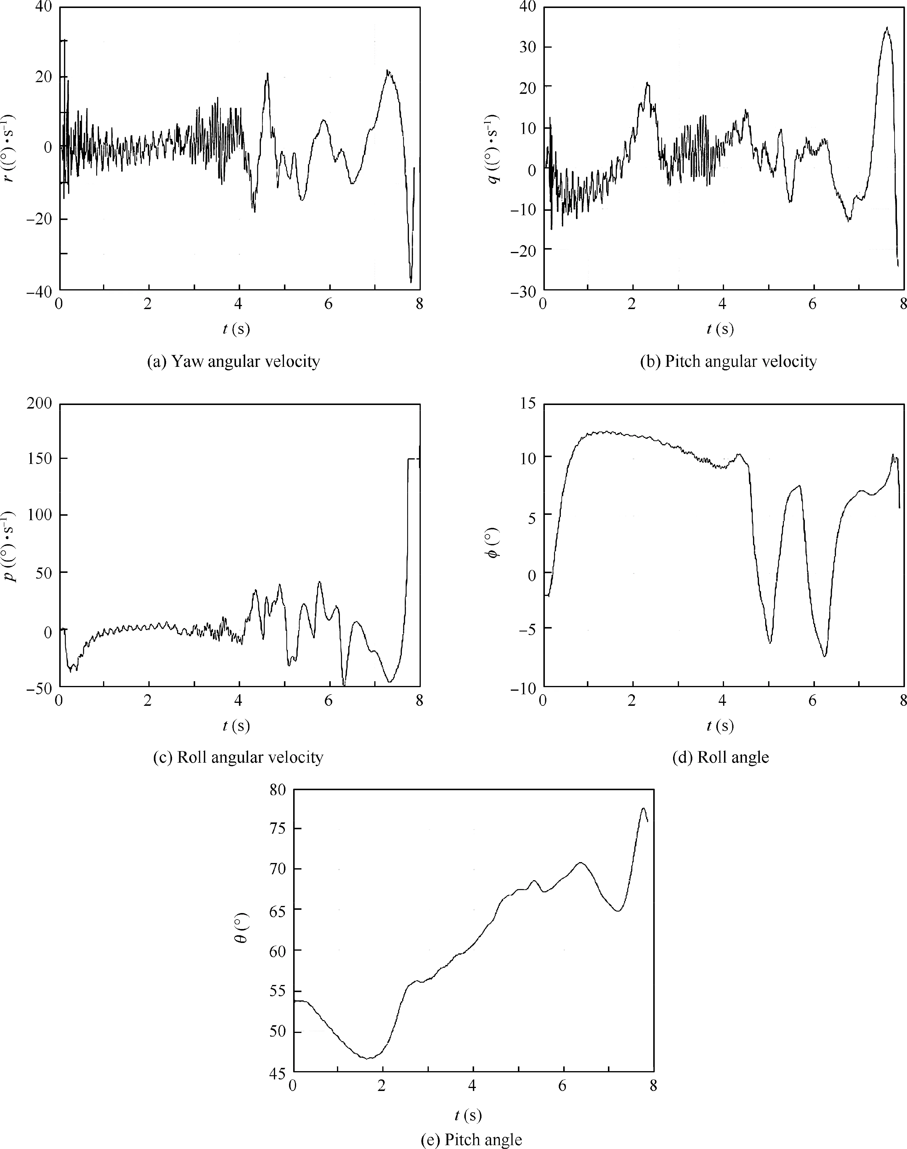
Fig. 8 Actual measurements of yaw angular velocity, pitch angular velocity, roll angular velocity, roll angle and pitch angle.
The step responses of roll angular velocity roll angle of platform with pitch angle θ=45◦and the roll angular velocity of the vehicle as step input (with amplitude 4469.4 (°)/s) are shown in Fig.7.It is observed that when the roll angular velocity of the vehicle increases sharply, the roll angular velocity of the platform only varies at a low speed, while the roll angle of the platform is almost unchanged. Therefore, the roll-isolated control is effective.
Fig.8 show the actual measurements of yaw angular velocity r,pitch angular velocity q,roll angular velocity p,roll angle pitch angle θ respectively.
By introducing the yaw angular velocity,pitch velocity and pitch angle obtained from the flight test, the evolution of the roll angular velocity with time is obtained. Fig. 9 shows the comparison between simulation and the flight test, where the full line pexpdenotes the roll angular velocity obtained from the test and the dotted line ppiddenotes the simulation result.
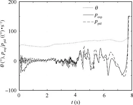
Fig. 9 Comparison of PID controller simulation results and measured data.
As shown in Fig. 9, both the roll-isolated control failure and the sharp increase in the roll angular velocity happen during simulation. After 7 seconds and the pitch angle exceeds 70°, the roll angular velocity increases sharply, and the rollisolated control fails. When the roll angular velocity exceeds 150(°)/s, the range of the roll gyro during the test gets saturated and becomes ineffective. Due to model parameters and random interference during the test, the simulation and test results do not completely coincide with each other. However,they are consistent in trend.
3.2. Mechanism of roll-isolated control failure
It can be seen from Fig.6 that the roll-isolated control system has two disturbance terms, yaw angular velocity r and pitch angular velocity q.The surface diagram of the two disturbance term amplification factors krand kqwith respect to pitch angle θ roll angle φ shown in Fig. 10. It is observed that the amplification factors of the disturbance term krand kqare increased with the increase of the pitch angle θ.Especially when the pitch angle θ is above 70◦,krand kqare increased significantly.Thus,some smaller disturbances in yaw angular velocity r and pitch angular velocity q can form a large strong input. This is the primary cause of the roll-isolated control failure.
Meanwhile,as shown in Fig.10,when the roll angle is close to 0 deg, kr, is larger, indicating that the yaw angular velocity is the main disturbance term. Similarly, when the roll angle is close to 90◦, kqis larger, indicating that the pitch angular velocity is the main disturbance term. During this flight test,as the roll angle is small(around 10°),the yaw angular velocity is the main disturbance.After about 7 s,a yaw angular velocity disturbance with the maximum magnitude of about 30 (°)/s occurs, resulting in the roll-isolated control failure.
Substitute Eq. (9) into Eq. (10), one can obtain the following equation:

Fig.11 shows the effect on roll angular velocity of PID and PI controller respectively,with r=q=30(°)/s.Evidently,the derivative element in the PID controller introduces additional disturbances, which aggravates the impact of yaw angular velocity and pitch angle,resulting in saturation of the roll gyro and failure of the roll-isolated platform ultimately.
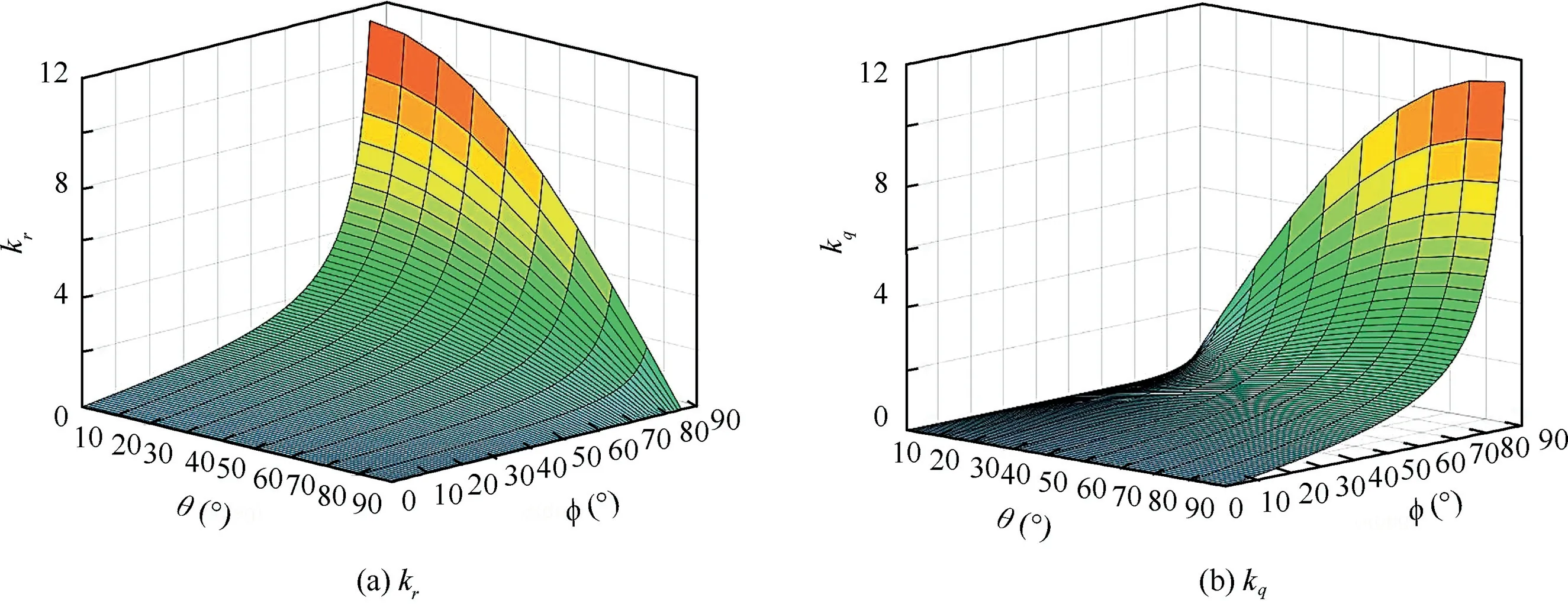
Fig. 10 Plot of disturbance term kr and kq.
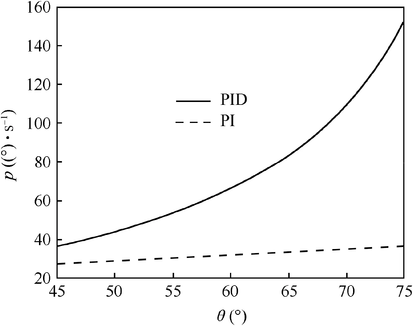
Fig.11 Effect on roll angular velocity of PID and PI controller.
4. The improved roll-isolated platform control method
4.1. Roll-isolated control system without the derivative element
According to the analysis of the reason for the roll-isolated failure with large pitch angle in Section 3.2, it is noticed that the derivative element in the PID controller aggravates the roll-isolated control failure. To deal with this problem, the PID controller of the platform control model is changed into PI controller, as shown in Fig. 12. With a 4469.94 (°)/s step input of the vehicle’s roll angular velocity pb, the roll angular velocity p and roll angle q of the platform under pitch angle θ=45oare illustrated in Fig. 13, in which the parameters are the same as those in Section 3.1.
Obviously,once the derivative element is removed, the system damping is decreased and severe oscillation occurs.Therefore, an inner feedback loop of the roll angular velocity is introduced to increase the damping, as shown in Fig. 14.
The control parameter of the roll angular velocity feedback loop in the improved roll-isolated PI control system is set as k1=5 and the other parameters are the same as those in Section 3.1.The parameters of the PI controller are set as:kP=30 and kI=150.
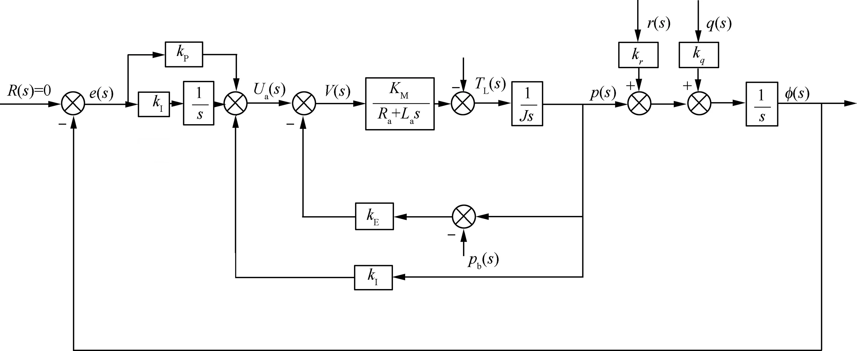
Fig. 12 Structure of the roll-isolated PI control system.
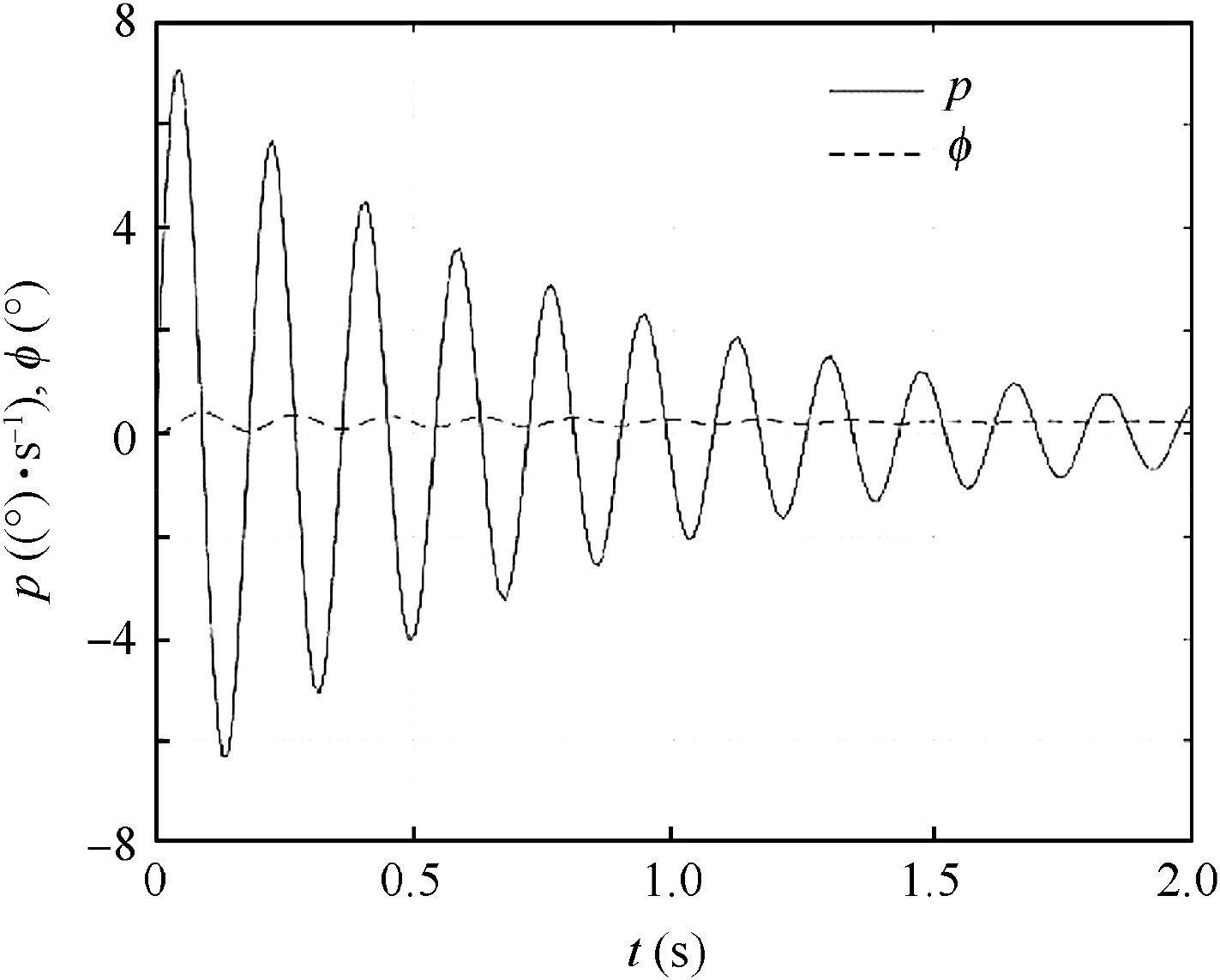
Fig.13 Step response of roll angular velocity and roll angle of PI controller.
Simulation is conducted to verify the effectiveness of the PI control model. Fig. 15(a) shows the step responses of roll angular velocity p and the roll angle φ of the platform with pitch angle θ=45oand vehicle roll angular velocity pb(amplitude 4469.94 (°)/s) as input. It is noticed that when the roll angular velocity of the vehicle varies rapidly, the roll angular velocity of the platform only varies slowly, indicating that the oscillation is effectively avoided. Moreover, the roll angle of the platform varies little, and the roll-isolated control is effective. Fig. 15(b) shows the step responses of roll angular velocity p and roll angle φ of the platform with pitch angle θ=75◦and pitch and yaw angular velocity as inputs (amplitude 30 (°)/s). Apparently, the roll angular velocity is effectively reduced, and thus the roll-isolated control system can work well. Meanwhile, the roll gyro is not saturated, and the variation of the roll angle of the platform is small. Therefore, the improved roll-isolated control system is effective.
4.2. Roll-isolated control system using direct feedback of roll angular velocity
When the roll angle is not required to be zero during the initial alignment process,the roll angular velocity can also be directly fed back to form the roll-isolated control system. The block diagram is shown in Fig. 16.
Fig.17 shows the roll angular velocity p and roll angle φ of the roll-isolated control system with direct feedback of the angular velocity, when the feedback loop control parameters are set as k2=5 and pitch angle θ=75◦, and the pitch and yaw angular velocity step from zero to 30 (°)/s.
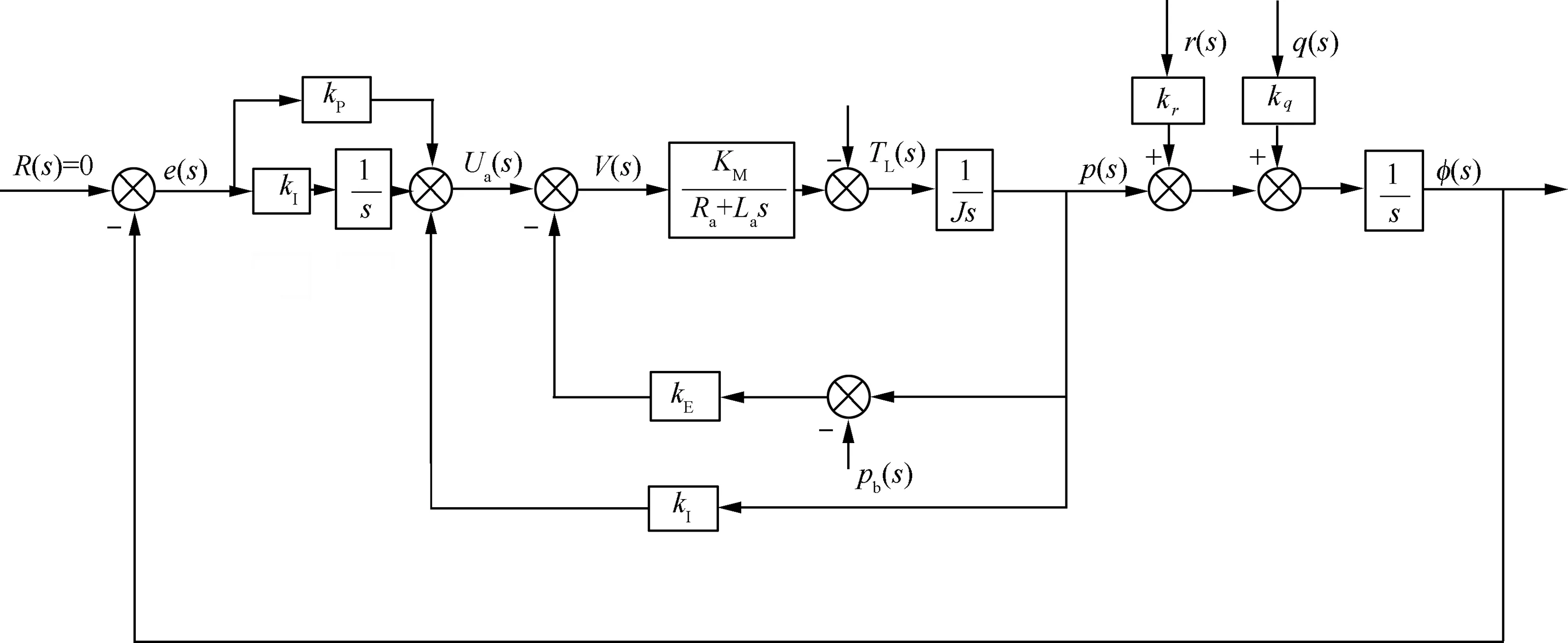
Fig. 14 Improved roll-isolated control system.
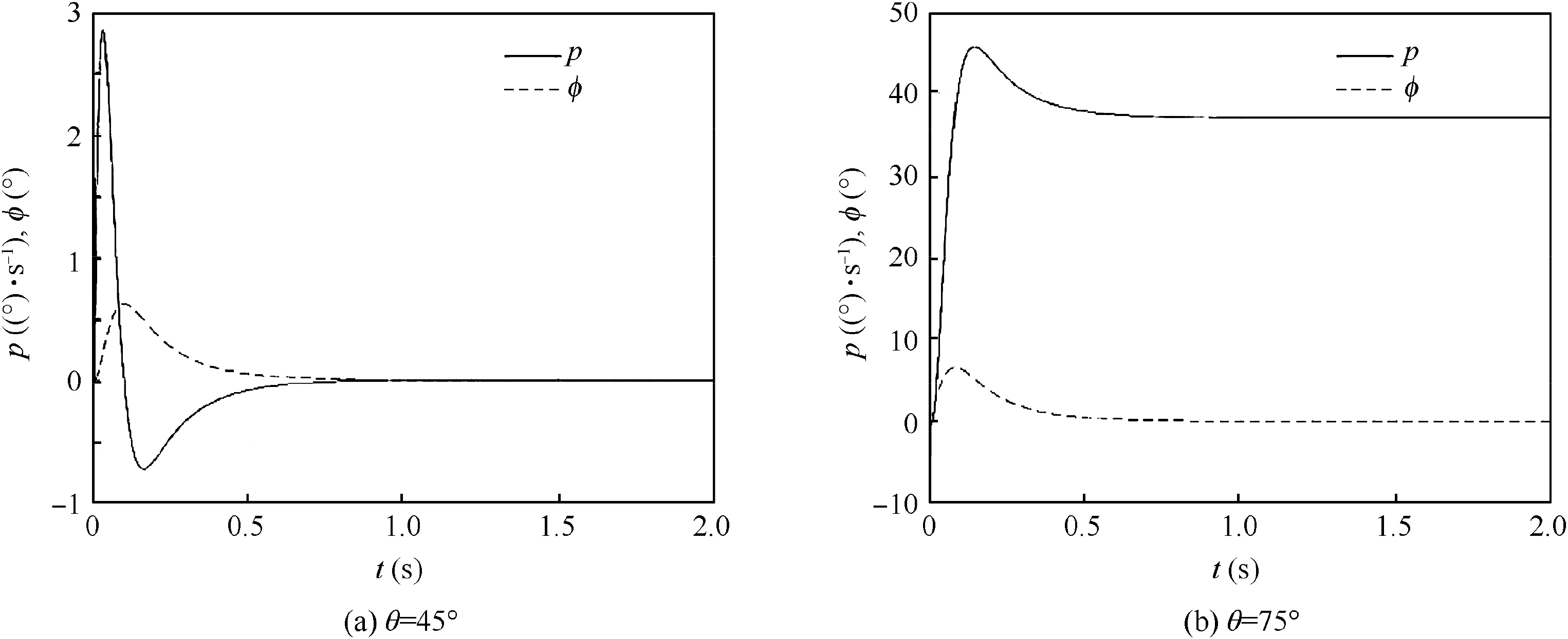
Fig. 15 Improved roll angle and roll angle step response.
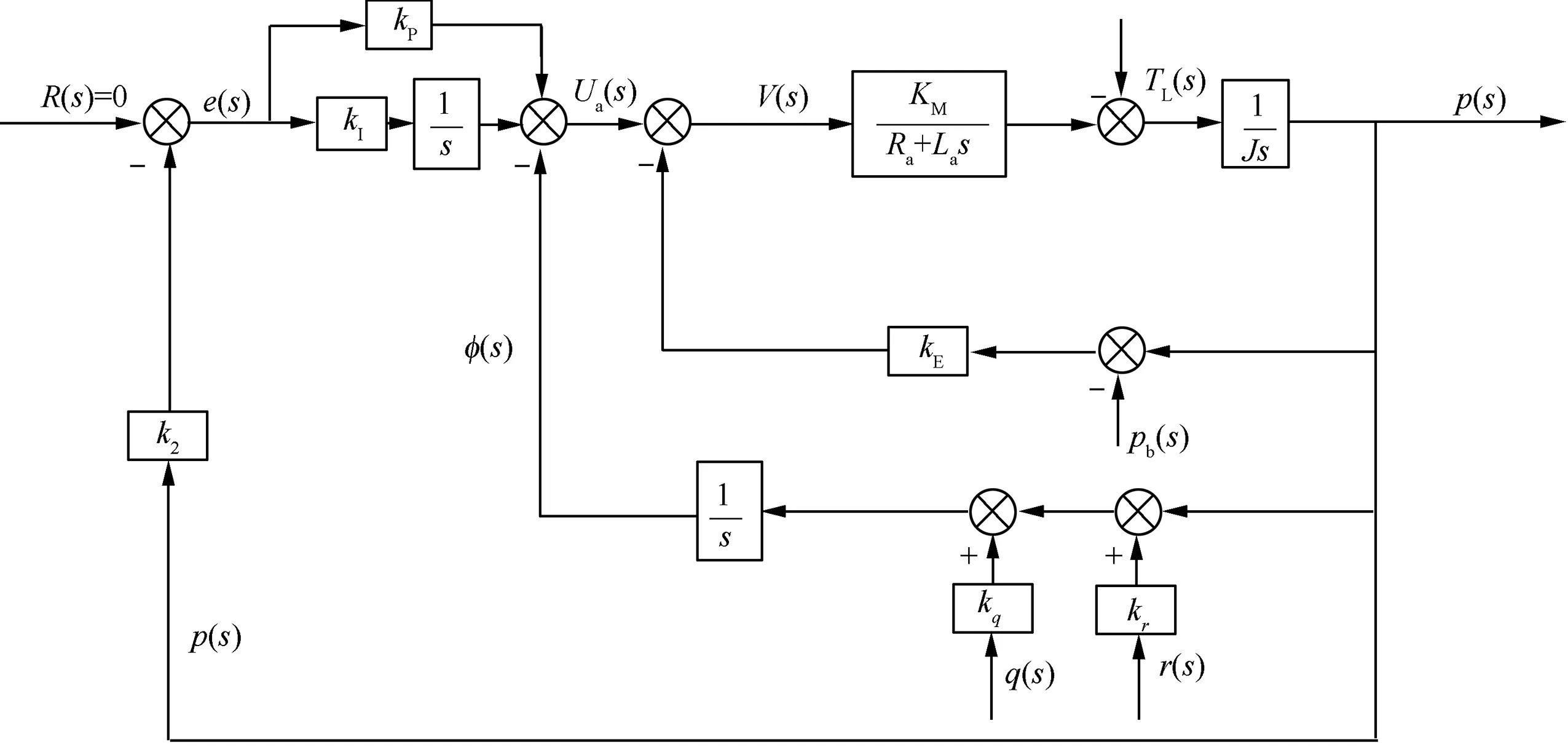
Fig. 16 Block diagram of the roll-isolated control system for direct feedback roll angular velocity.
Compared with Fig. 15(b), with the same pitch angular velocity q and yaw angular velocity r disturbance, the variation of roll angular velocity p is smaller, while the roll angle φ increases continuously. Therefore, future research should focus on designing a strong anti-disturbance system, to stabilize both the roll angle and the roll angular velocity under large pitch and yaw angular velocity disturbance.
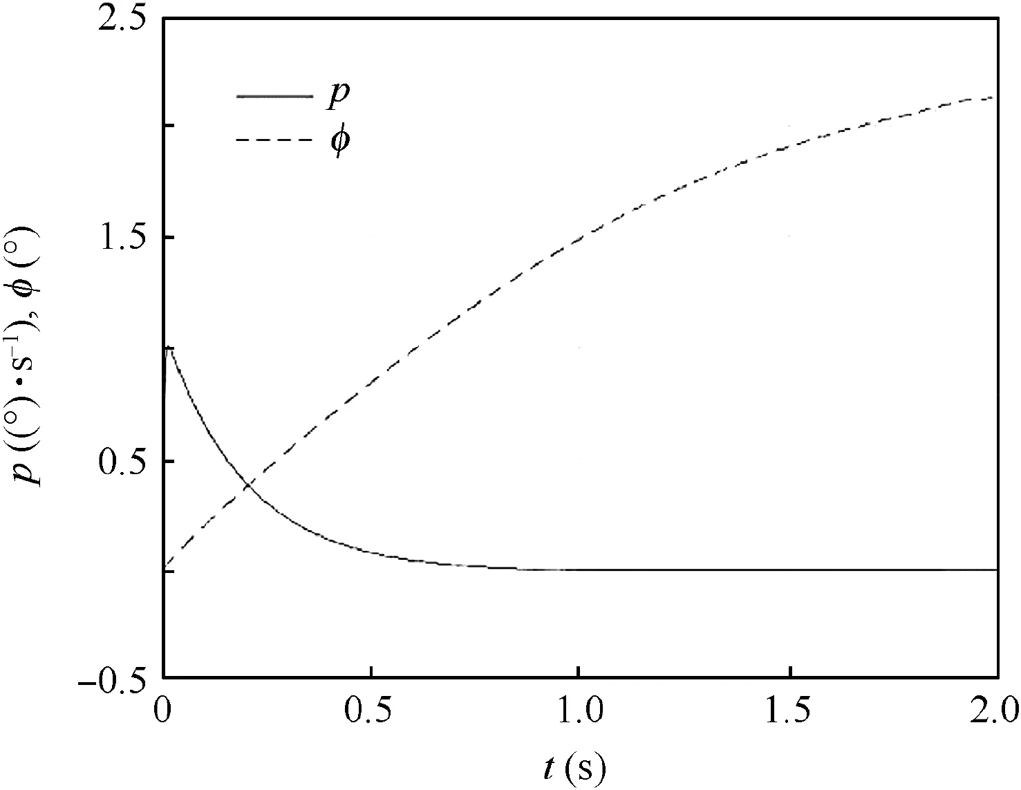
Fig.17 Angular velocity curve of roll-isolated control system for direct feedback roll angular velocity.
5. Conclusion
This paper presents an analytical analysis of the control system of the roll-isolated SINS. The governing equation of the rollisolated control system has been derived, considering various disturbance factors. It has been demonstrated that the pitch and yaw angular velocity can result in roll-isolation failure for the control system with the roll angle as the feedback under large pitch angle.It has been revealed that the large pitch angle can amplify the disturbance of the pitch and yaw angular velocity dramatically and result in failure of the roll-isolated control which induces saturation of the roll gyro range.Meanwhile, the derivative element in the PID controller is harmful and can introduce additional disturbance terms, which aggravates the disturbance of the pitch and the yaw angular velocity,and accelerates the failure of the roll-isolated control.
An improved scheme of the roll-isolated control system has been proposed,which eliminates the derivative element in PID controller and introduces a roll angular velocity feedback to increase the damping.Simulation results show that the scheme can reduce the disturbance effect of pitch and yaw angular velocity under large pitch angle to some extent, and reduce the possibility of the roll-isolated control failure. It has been also demonstrated that the only roll angular velocity feedback cannot stabilize the roll angle although it can eliminate the disturbance of the pitch and yaw angular velocity under the large pitch angle completely. Future research may focus on the architecture of strong anti-disturbance control system, which can effectively suppress the influence of pitch and yaw angular velocity disturbance and achieve roll angle control stability as well.
Acknowledgments
This study was co-supported by the National Science Foundation of China(No.11532002)and Science Challenge Project of China (No. TZ2018001).
 CHINESE JOURNAL OF AERONAUTICS2020年10期
- CHINESE JOURNAL OF AERONAUTICS的其它文章
- A novel surrogate modeling strategy of the mechanical properties of 3D braided composites
- A user-friendly yield criterion for metals exhibiting tension-compression asymmetry
- Aerodynamic characteristics of morphing wing with flexible leading-edge
- High cycle fatigue failure with radial cracks in gears of aero-engines
- Motion equations of hemispherical resonator and analysis of frequency split caused by slight mass non-uniformity
- Light weight optimization of stratospheric airship envelope based on reliability analysis
