Nonlinear dynamic behavior of a flexible asymmetric aero-engine rotor system in maneuvering flight
Tian GAO, Shuqian CAO,*, Yongtao SUN
a Department of Mechanics, Tianjin University, Tianjin 300354, China
b Tianjin Key Laboratory of Nonlinear Dynamics and Control, Tianjin 300354, China
c National Demonstration Center for Experimental Mechanics Education, Tianjin University, Tianjin 300354, China
KEYWORDS Aero-engine rotor system;Ball bearings;Maneuvering flight;Nonlinear dynamics;Squeeze film dampers
Abstract Aero-engine rotor systems installed in aircraft are considered to have a base motion. In this paper,a flexible asymmetric rotor system is modeled considering the nonlinear supports of ball bearings and Squeeze Film Dampers (SFDs), and the dynamic characteristics of the rotor system under maneuvering flight are systematically studied. Effects of the translational accelerative motions, the angular motions and the pitching flight with combined translational and angular motions on nonlinear dynamic behavior of the rotor system are investigated.The results show that,due to the nonlinear coupled effects among the rotor,ball bearings and SFDs,within the first bending resonance region,responses of the rotor show obvious nonlinear characteristics such as bistable phenomenon, amplitude jumping phenomenon and non-synchronous vibration. Translational acceleration motion of the aircraft leads to axis offset of the rotor system and thus results in the reduction and the final disappearance of the bistable rotating speed region. The pitching angular motion mainly affects rotational vibration of the rotor system,and thus further induces their transverse vibrations.For the pitching flight with combined translational and angular motions,a critical flight parameter is found to correspond to the conversion of two steady responses of the rotor system, in which one response displays small amplitude and synchronous vibration, and the other shows large amplitude and non-synchronous vibration.
1. Introduction
Maneuvering flight, which can be regarded as the changes of an aircraft’ s flight status, has a great influence on the dynamics of the aero-engine rotor systems.1,2It is unavoidable for an aircraft to perform maneuvering flight especially in the air combats. When the aircraft is maneuvering, the aero-engine rotor system usually suffers additional inertial forces and gyroscopic moments which possibly lead to large transient vibrations and even instability because of the highly nonlinear supporting structure of the aero-engine. So, it is necessary to consider the influence of the maneuvering flight for the reliable design of the aero-engine.
In recent years,much attention has been paid to the effects of the maneuvering flight on the vibration response of rotor systems. A general model of the rotor system was established by Zhu and Chen3,4,in which all kinds of the maneuvers were considered. The results showed that the influence of the maneuvering flight resulted in additional damping effects,stiffness effects, inertial forces and gyroscopic moments of the rotor system. Lin et al.5,6studied the dynamic responses of a cracked rotor system with aircraft maneuvering at constant speed or acceleration, wherein the climbing angle and acceleration of the aircraft remarkably affected the parameter range for bifurcation, chaotic response and system stability. Han and Chu7studied a cracked rotor-bearing system under timevarying base angular motions, including the rolling, pitching and yawing motions. It was concluded that the transverse crack would induce the sub-critical resonances and combination critical resonances to the base excited system.Yang et al.8investigated the transient bifurcation of a cracked rotor system under the influence of the hovering flight. They found three ways for cracked rotor responses going to chaos, namely through quasi-periodic, intermittence, or period-3 bifurcation to chaos. Hou et al.9analyzed the nonlinear responses caused by aircraft hovering flight in a rub-impact rotor system. The influence of the maneuver load resulted in the periodic, subharmonic and quasi-periodic motions of the system. In addition, they10,11studied the bifurcation responses and stability of a rotor system with cubic stiffness.It was found that the resonance regions of the rotor shifted to the right when the aircraft was maneuvering. El-Saeidy and Sticher12carried out the dynamic analysis of the rotor with bearing cubic nonlinearity, in which six motions at the machine base were taken into account. The results showed that the spectrum of the rotor response was marked with sum and difference frequency tones caused by the rotating unbalance frequency and the base excitation frequency.Sinha13studied the transient dynamics of an asymmetric rotor system,which was subjected to an impulsive load due to sudden blade release and subsequent sustained rotation. The magnitude of the contact load was quantified during windmilling of the damaged rotor with a blade missing.
Refs. 9-13 mostly focus on the nonlinear characteristics of the fault rotor system under maneuvering flight, and the supporting structures of the rotor are simplified. However, the supporting system of the aero-engine is highly nonlinear,including ball bearings and Squeeze Film Dampers (SFDs),which could lead to the complex vibration responses.Extensive researches have showed that the rotor system with SFDs led to complicated nonlinear behavior, such as amplitude jumping and bistable phenomenon.14-16Zhu et al.17studied the multisolution response in a flexible rotor system supported on SFDs through synchronous circular centred-orbit motion solution,numerical integration method and slow acceleration method,in which resonant, isolated bifurcation and swallowtail bifurcation multiple solutions were found. Chen et al.18,19investigated the dynamic characteristics of a flexible rotor with SFD excited by two frequencies. It was found that the motion of the rotor showed a kind of ‘cross’, ‘soft spring’ or ‘hard spring’ characteristics with the variation of the ratio of the two excitation frequencies. Zhou et al.20studied the nonsynchronous motion response of a rotor system supported on ball bearings with floating-ring squeeze film dampers.They indicated that the speed range of non-synchronous motion response of the rotor system increased as the supporting stiffness increased.Modaresahmadi et al.21also observed the nonperiodic and chaotic response in a rotor system supported on ball bearings with centralizing springs and SFDs.
Refs.14-21,studying the nonlinear effects of SFDs and ball bearings, mainly focus on dynamic responses of the aeroengine rotor system which is fixed to the ground. However,during the actual flight of the aircraft, maneuvering flight and the coupled effects among the rotor, ball bearing and SFDs, could happen simultaneously, which might lead to undesired dynamic responses of the aero-engine.In this study,by simplifying the aero-engine as a flexible asymmetric rotor model considering the nonlinear supports of ball bearings and SFDs, the dynamic characteristics of the rotor system under maneuvering flight are systematically investigated. The governing equation of motions is solved by using the numerical integration method.Effects of the translational accelerative motions, the angular motions and the combined translational and angular motions on nonlinear dynamic behavior of the aero-engine rotor system are investigated. The research of this study provides a deeper and more comprehensive theoretical basis for the nonlinear characteristics uncovering and stability design of the aero-engine rotor system.
2. Mathematical modeling
2.1.Geometrical model of asymmetric rotor system supported on ball bearings with SFDs
As shown in Fig. 1, the aero-engine rotor system is simplified as an asymmetric rotor model,supported on ball bearings with SFDs at the two ends.The rotor system includes the following fundamental components:the rotating disk,the shaft,the ballbearings,the SFDs and the elastic support.The rotating disk is assumed to be rigid with a constant rotation speed Ω.Besides,the mass of the rotating disk is described by md,mband moare the lumped mass at the two ends of the shaft and the lumped mass of the outer race of the ball bearings, kais the support stiffness of the elastic support, l1and l2are the lengths of the shafts.

Fig.1 Schematic diagram of asymmetric rotor system supported on ball bearings with SFDs at two ends.
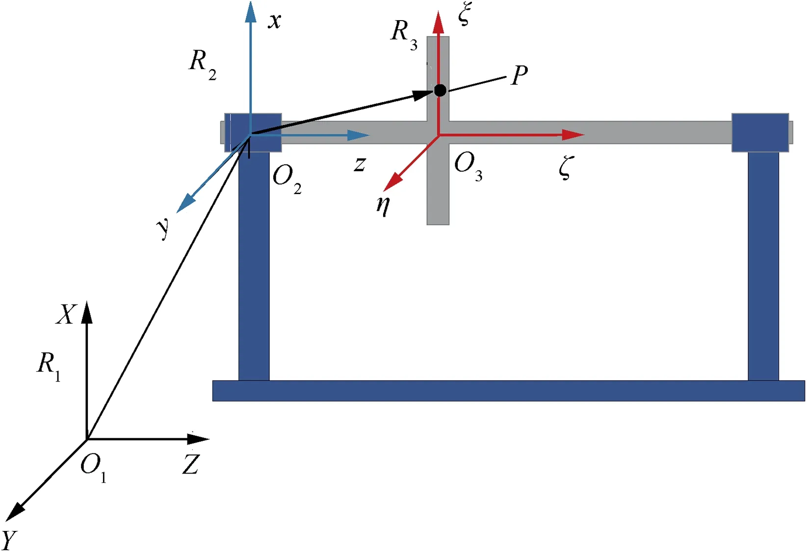
Fig. 2 Schematic diagram of three Cartesian coordinated references O1XYZ, O2xyz and O3ξηζ.
To conveniently describe the flight status of the aircraft,three Cartesian coordinated references, O1XYZ, O2xyz and O3ξηζ, are used (Fig. 2). The inertial reference frame O1XYZ, fixed to the ground, is used to describe the spatial location of the aircraft. The non-inertial reference frame O2xyz, fixed to the aircraft, is used to describe the rotational direction of the aircraft with respect to the ground. The local reference frame O3ξηζ, fixed to the rigid disk, is used to describe the vibration of the rotor with respect to the aircraft.For the convenience of expression, the three reference frames are named as the inertial reference frame R1, the non-inertial reference frame R2and the local reference frame R3, respectively. And the base vectors of the three reference frames are defined as (i1, j1, k1), (i2, j2, k2) and (i3, j3, k3), respectively.The flight status of the rigid aircraft can be completely represented by the translational components Xb, Yband Zbof the inertial reference frame R1and the three rotational components θbx(the yawing angle), θby(the pitching angle) and θbz(the rolling angle) of the aircraft relative to the ground.
2.2. Equation of motion of asymmetric rotor system in maneuvering flight
Lagrange’s equation is used to derive the equation of motion of the rotor system. It is expressed as22

where T is the kinetic energy of the rotor system,qiis the generalized coordinate in the ith degree of freedom, and Qiis the generalized force corresponding to qi. The process is as follows.First,the kinetic energy,the generalized forces of the ball bearings and the squeeze film forces of the rotor system are calculated.Then,the differential equations of motion of the rotor system in maneuvering flight are obtained by inserting the kinetic energy and the generalized forces of the rotor system into the Lagrange’s equation given in Eq. (1).
2.2.1. Kinetic energy
As shown in Fig. 1, the rotor system includes three kinds of independent component elements: the rotating disk, the lumped mass at the two ends of the shaft and the lumped mass of the outer race of the ball bearings. Therefore, the kinetic energy of the rotor system is the sum of kinetic energies of the three kinds of independent component elements.One thing noteworthy is that only the process for calculating the kinetic energy of the rotating disk is shown in this paper, and the kinetic energies of the other two component elements could be similarly obtained.
Kinetic energy T of the rotating disk, consisting of the translational kinetic energy Ttand the rotational kinetic energy Tr, is expressed as
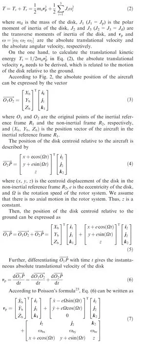
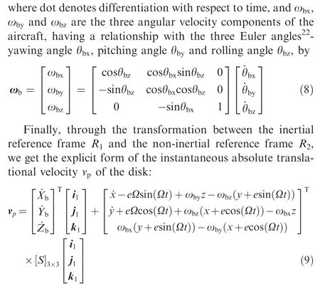
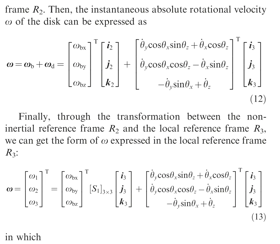
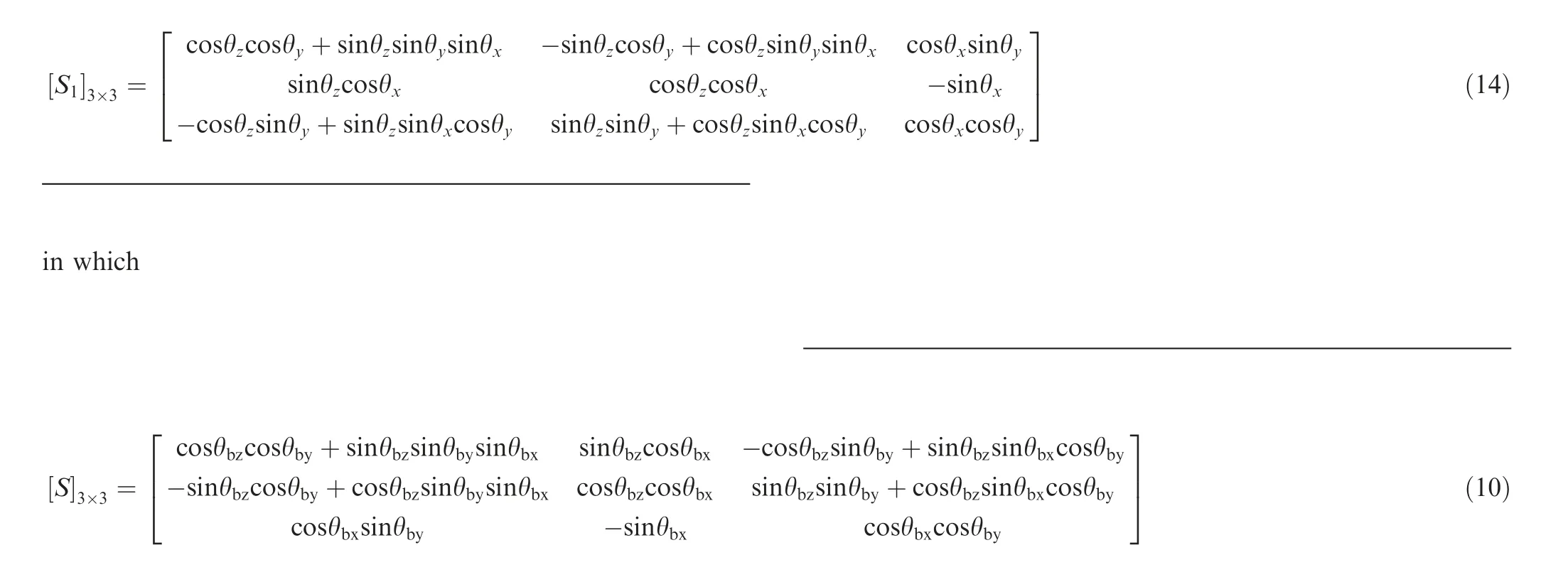
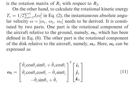
in which θx, θyand θzare the rotational Euler angles of the local reference frame R3relative to the non-inertial reference is the rotation matrix of R2with respect to R3.
In the end, substituting Eq. (9) and Eq. (13) into Eq. (2)gives the kinetic energy T of the rotating disk. Similarly,kinetic energies of the lumped mass at the end of the shaft and the lumped mass of the outer race of the ball bearings can be obtained.
2.2.2. Ball bearing force
The ball bearing model is shown in Fig.3.The inner race of the ball bearing is fixed on the shaft and the outer race is joined together with the SFD. According to Ref. 20, the ball bearing forces can be simplified as

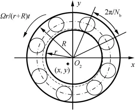
Fig. 3 Ball bearing model of rotor system.20
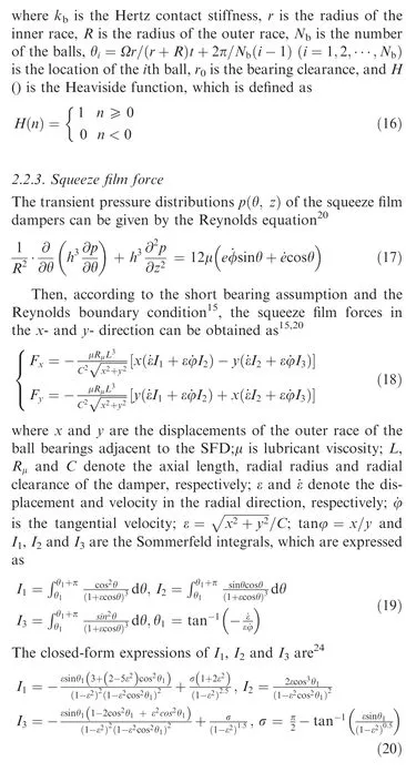
2.2.4. Equation of motion
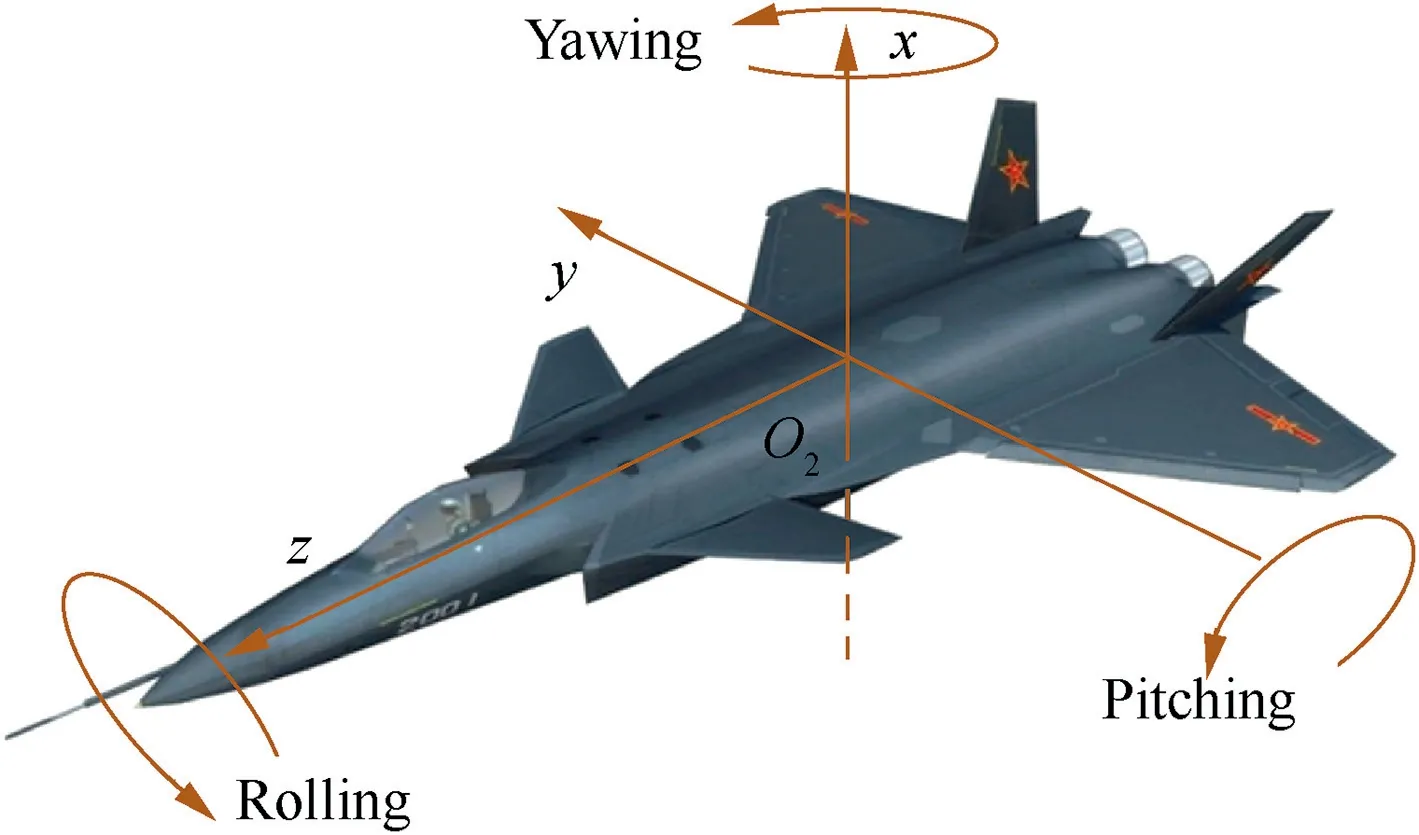
Fig. 4 Schematic diagram of maneuvering flights of aircraft.
The schematic diagram of maneuvering flights, including pitching, hovering and rolling, of the aircraft is shown in Fig. 4. In this paper, the pitching flight is chosen to show the nonlinear dynamic behavior of the flexible asymmetric aeroengine rotor system supported on ball bearings with SFDs in maneuvering flights.That’s to say,only the maneuvering flight in the vertical O2-xz plane is considered,which means that the yawing angle θbxand the rolling angle θbzare neglected.Therefore, Eq. (8) can be simplified as ωby= ˙θbyand the rotation angle θzis replaced by Ωt whose derivative with respect to time is the constant Ω.At the same time,since the rotation angles θxand θyof the rotating disk are very small, their trigonometric functions can be approximated as
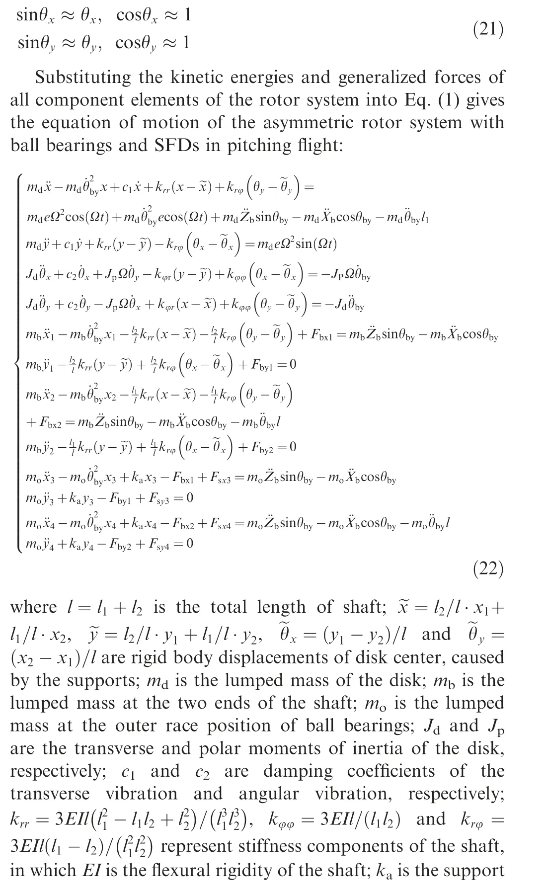
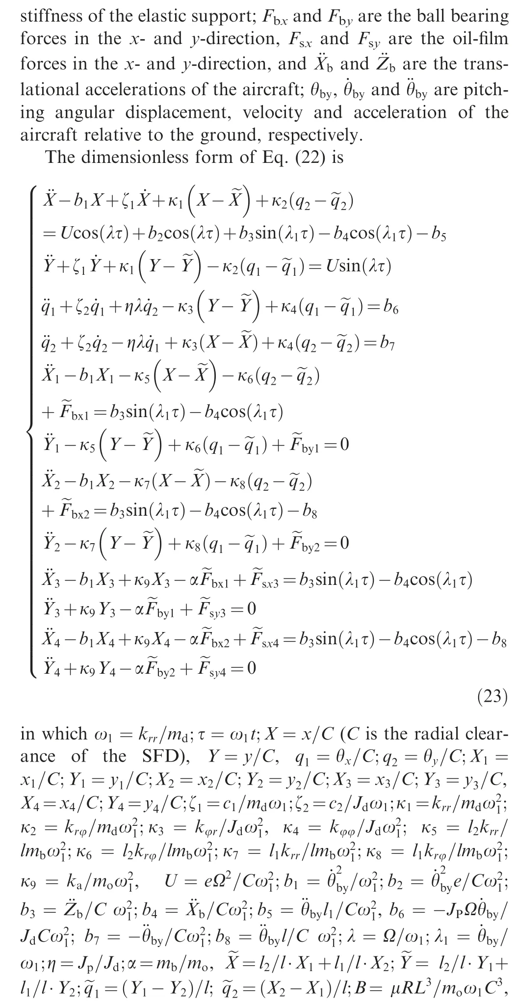
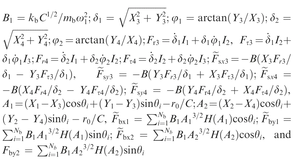
3. Model validation
Based on the rotor model with SFDs in Ref.19,the rotor system in this paper further takes ball bearings and maneuvering flight into account.In order to validate the rotor model of this paper, here, validation of SFD model of this paper is chosen for illustration. Under the same computational conditions,numerical results of this paper are compared with those of Ref. 19. The results are presented in Fig. 5, where A5is the dimensionless amplitude of left end of the shaft,and λ denotes dimensionless rotational speed ratio. Fig. 5(a) shows the results of Ref.19 obtained by the Runge-Kutta(R-K)method and the Harmonic Balance (HB) method. Fig. 5(b) shows the results of this paper obtained by the Runge-Kutta method.By comparing Fig. 5(b) with Fig. 5(a), it is obvious that numerical results of this paper agree well with those of Ref.19 in general. This, to some extent, indicates that the model established in this paper is validated.
4. Nonlinear dynamic responses and discussion
According to Refs. 19,20, the simulation parameters of the rotor model and the supporting system are listed in Table 1.Because of the strong nonlinearity of the rotor system supported on ball bearings with SFDs,19,20the fourth Runge-Kutta method with variable step is adopted to solve Eq.(23). The integral accuracy of the Runge-Kutta method is set to 10-12by using the function ‘‘ode45” in MATLAB. When the rotational speed of the rotor system is increased or decreased step by step, choosing the steady state response of the previous rotational speed as the initial value for the next rotational speed would save much computing time.
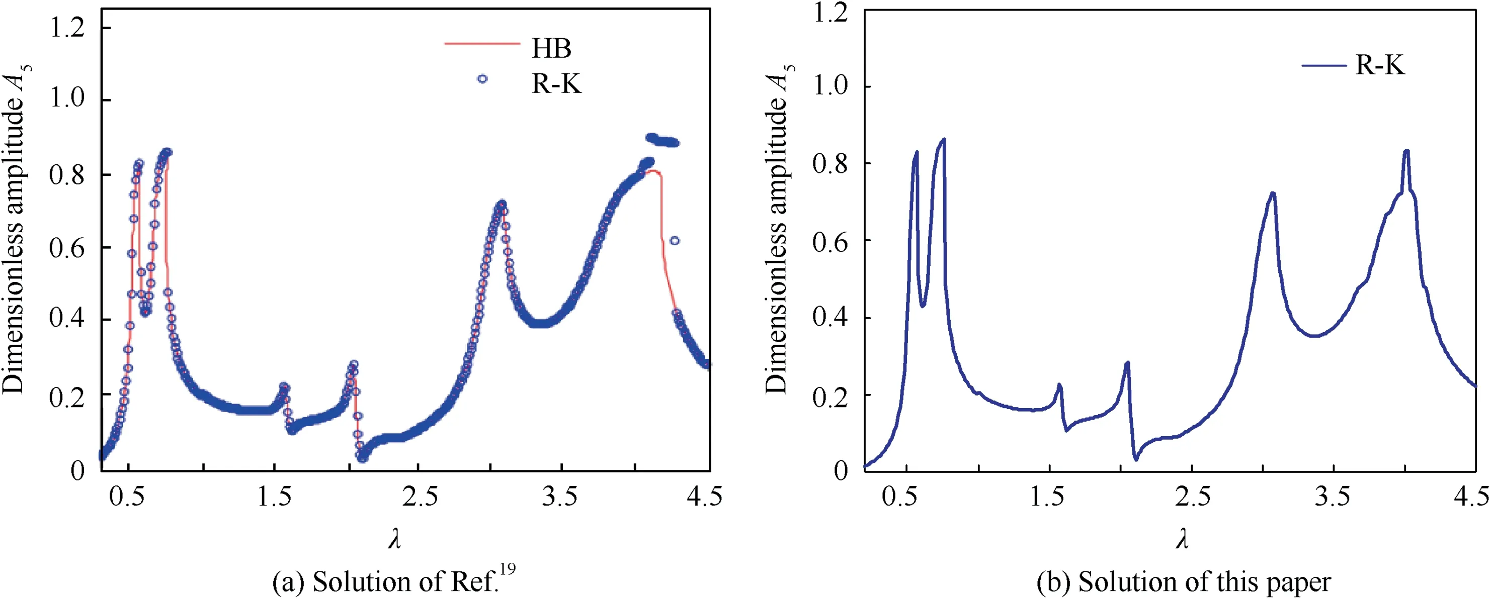
Fig. 5 Dimensionless amplitude-frequency results of left end of shaft.

Table 1 Parameters of rotor model.
In order to have a clear understanding of the inherent characteristics of the rotor system, the natural modes are investigated firstly. After that, it would be helpful for us to understand the responses of the rotor system in maneuvering flight clearly. Ignoring the nonlinear supporting of the ball bearing and the SFDs,the first three order natural frequencies of the rotor system in the x-and y-direction are calculated and listed in Table 2. The first two modes correspond to the rigid body translational mode and rigid body rotational mode of the rotor system, respectively. The third mode corresponds to the first bending mode of the rotor system.
4.1. Effect of aircraft’s translational motion
When aircraft maneuvers at a constant speed, the vibration of the rotor is equivalent to that of the rotor fixed to the ground.But if the aircraft maneuvers at a constant rate of acceleration,the rotor system will be subjected to additional inertial forces and the vibration of the rotor system will be affected.To show the effect of the aircraft’s translation acceleration on the nonlinear dynamic behavior of the asymmetric rotor system supported on ball bearings with SFDs, the translational acceleration of the aircraft in the vertical plane is chosen as the examples for illustration. We assume that pitching angle of the aircraft is fixed. Then, the translational acceleration of the aircraft in inertial reference frame R1could always be divided into two parts, the tangential acceleration along the axis of the rotor and the normal acceleration perpendicular to the axis of the rotor. Since the axial displacement of the rotor is ignored, the effect of the tangential acceleration along the axis of the rotor on nonlinear dynamic behavior of the rotor system could also be ignored. Then, only the normal acceleration perpendicular to the axis of the rotor could affect the nonlinear dynamic behavior of the rotor system. Defining the normal acceleration perpendicular to the axis of the rotor as H, from Eq. (22) we can get H= ¨Zbsinθby- ¨Xbcosθby.Apparently, the translational normal acceleration H is the parameter that in fact determines and reflects the effect of translational acceleration on nonlinear dynamic behavior of the rotor system.
4.1.1. Effect of rotating speed under different translational acceleration
First, nonlinear dynamic behavior of the rotor system, under different translational normal acceleration H and varied rotor rotation speed Ω, is investigated, in which H=0, 20, 40 m/s2and Ω=0-3000 rad/s.The amplitude and axis offset(center position of the rotor’s axis trajectory) of the left end of the shaft are chosen as the examples for illustration. The amplitude-rotation speed curves and axis offset-rotation speed curves of the left end of the shaft during the acceleration and deceleration processes for H=0, 20, 40 m/s2are shown in Figs. 6-8, respectively. Hereinto, A(X1) and E(X1) are the dimensionless amplitude and dimensionless axis offset of the left end of the shaft in the x-direction. And the curves with red dots and blue circles denote the stationary responses of the acceleration process and the deceleration process,respectively.
From Fig. 6(a), we can see that for H=0 (i.e.,¨Zbsinθby- ¨Xbcosθby=H=0, without the translational normal accelerated motion),there are three resonance peaks, corresponding to the first three order natural frequencies,respectively. The nonlinear characteristics of the rotor system are mainly focused on the region around the first bending resonance critical speed (Table 2 and Fig. 6(a)). The multisolution response (bistable phenomenon) is found around the region of the first bending resonance critical speed. When the rotation speed overruns the first bending resonance critical speed, the amplitude of the rotor system does not decrease until the rotation speed reaches a certain value and after that the amplitude drops suddenly. Moreover, when the rotation speed slows down and goes through the first bending resonance, the responses of the rotor system keep small amplitude at first and then rise to large amplitude at another certain rotation speed.These jumping and bistable phenomena,caused by the coupled effects among the rotor, ball bearings and SFDs,are the same as the conclusion of Ref. 20. In addition, from Fig.6(b),it is obvious that there is no axis offset if the aircraft maneuvers at a constant speed.
When the translational normal acceleration increases from H=0 to H=20 m/s2,comparing Fig.7(a)with Fig.6(a),we can see that the topological structure of the amplitude-rotation speed curve does not change too much.But the jumping ampli-tude and the bistable speed region of the rotor system are greatly reduced for H=20 m/s2. Meanwhile, from Fig. 7(b),we can see that the center position of rotor’s axis trajectory is offset when the aircraft maneuvers at an accelerated translational motion. When the rotating speed is far from the resonance critical speed, the axis offset is relatively large because vibrating amplitude of the shaft is relatively small and the suppression effect of the SFD on the rotor vibration is relatively weak. However, when the rotor rotation speed is near the resonance critical speed, the axis offset is greatly suppressed,because, with the increase of vibration amplitude of the shaft,the nonlinear suppression effect of the SFD will be enhanced greatly. In addition, when the rotation speed is near the first bending critical speed (Fig. 7(b)), the bistable and jumping phenomena appear for the axis offset,due to the coupled nonlinear effect of the rotor system.
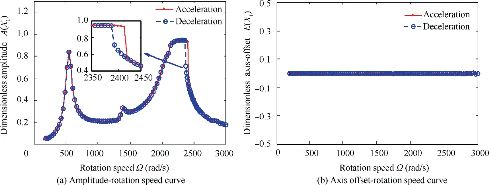
Fig. 6 Responses of left end of shaft during acceleration and deceleration process with Ω=0-3000 rad/s and H=0 (i.e.,¨Zbsinθby- ¨Xbcosθby =H=0).
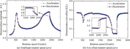
Fig. 7 Responses of left end of shaft during acceleration and deceleration process with Ω=0-3000 rad/s and H=20 m/s2 (i.e.,¨Zbsinθby- ¨Xbcosθby =H=20 m/s2).
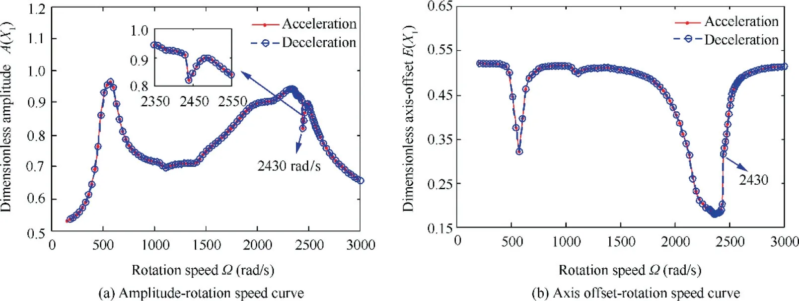
Fig. 8 Responses of left end of shaft during acceleration and deceleration process with Ω=0-3000 rad/s and H=40 m/s2 (i.e.,¨Zbsinθby- ¨Xbcosθby =H=40 m/s2).
When the translational normal acceleration continues increasing to H=40 m/s2(Fig.8),bistable phenomena disappear in both the amplitude-rotation speed curve(Fig.8(a))and the axis offset-rotation speed curve (Fig. 8(b)). But the jump phenomena still exist in the first bending critical speed. Meanwhile, by comparing Fig. 8(b) with Fig. 7(b), we can see that the axis offset of the left end of the shaft is more apparent for H=40 m/s2.And because of the sudden rise of axis offset at 2430 rad/s within the first bending resonance region, the stronger inhibition effect of the SFD limits the amplitude,which experiences the process of decreasing, recovering and reducing again.
The variation of the bistable speed region ΔΩ with H(H=0-40 m/s2) is shown in Fig. 9. From Fig. 9, we can see that for H=0 m/s2(i.e., without the translational normal accelerated motion), the bistable speed region is the biggest,which reaches to 37 rad/s. With H increasing from 0 to 40 m/s2, the bistable speed region reduces almost linearly and finally disappears at H=40 m/s2. This demonstrates that axis offset of the rotor system caused by translational acceleration motion of the aircraft could inhibit the formation of the bistable phenomena and even eliminate it when H is big enough.
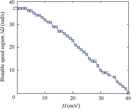
Fig. 9 Variation of bistable speed region ΔΩ with H.
4.1.2. Effect of translational acceleration
To show the nonlinear response of the rotor system with fixed rotation speed Ω but varied translational normal acceleration H, the parameters Ω=2390 rad/s (near the first bending critical speed and within the bistable region), amplitude, axisoffset and periodic motion of the left end of the shaft,are chosen as the examples for illustration.
In the first place, the amplitude-H curve and axis offset-H curve of the left end of the shaft during the processes of H(H=0-40 m/s2) increasing and decreasing are investigated.They are shown in Figs. 10(a) and (b), respectively. From Fig.10(a),we can see that,in the process of H increasing,when there is no translational normal acceleration (i.e., H=0), the rotor system vibrates with small steady amplitude at first.With the translational normal acceleration H increasing from 0 to 18 m/s2,the amplitude of the rotor system increases almost linearly. However, when it increases to H=19 m/s2, the amplitude suddenly jumps up and keeps almost constant until it increases to H=30 m/s2.Then,with H increasing from 30 m/s2to 40 m/s2,the amplitude slightly decreases.With respect to the process of H decreasing from 40 m/s2to 0 m/s2,it is apparent that in the range from H=40 m/s2to H=19 m/s2, the path of amplitude of the rotor system coincides with that of the process of H increasing from H=19 m/s2to H=40 m/s2. However, in the range from H=19 m/s2to H=0 m/s2,the amplitude of the rotor system does not return back but keeps almost a large steady state response.
Regarding the axis offset-H curve, from Fig. 10(b), we can see that,when H=0,there is no axis offset.With H increasing from 0 to 18 m/s2, the axis offset of the rotor system increases also almost linearly.But when H increases to 19 m/s2,the axis offset suddenly decreases, which is corresponding to the sudden rise of amplitude in Fig. 10(a). This happens because the sudden rise of amplitude enhances the damping effect of the SFD, which greatly suppresses the offset of the rotor system.For the process of H decreasing from 40 m/s2to 0, because the amplitude does not change obviously (Fig. 10(a)), the axis offset of the rotor system deceases gradually. Similarly, in the range from H=40 m/s2to H=19 m/s2, the process for the axis-offset coincides with that for H increasing from 19 m/s2to 40 m/s2. But for the range from H=19 m/s2to H=0,there is no jumping phenomenon.
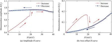
Fig. 10 Responses of left end of shaft during processes of H increasing and decreasing, with H=0-40 m/s2 and Ω=2390 rad/s (near the first bending critical speed).
In the second place,periodic vibrations of the left end of the shaft are investigated when the rotor rotating speed is within the bistable region. The corresponding waterfall curves, with Ω=2390 rad/s and H=0-50 m/s2, during the processes of H increasing and decreasing are given in Figs. 11(a) and (b),respectively.
From Fig. 11(a), we can see that, in the process of H increasing, when H is small, the response of rotor system is mainly based on the rotation frequency and shows no harmonic component. But when it increases to H=19 m/s2,the harmonic components appear suddenly. Except the rotating frequency 380.4 Hz, the response consists of some irreducible frequencies such as 117.9 Hz, 270.1 Hz and 498.3 Hz. This phenomenon is due to the rise of amplitude shown in Fig. 10(a). Since steady state response of the rotor system jumps from the small amplitude to the big amplitude,the corresponding vibration of the rotor system changes from single rotation frequency motion to harmonic motion. Then,with H increasing to a larger value, because larger axis offset increases the damping effect of the oil film, the response of the rotor system returns to the single rotation frequency response again.
The waterfall curve,with H decreasing from 50 m/s2to 0,is shown in Fig. 11(b). It can be seen that as H decreases from 50 m/s2to 19 m/s2, the periodic response of the rotor system is the same as that for H increasing from 19 m/s2to 50 m/s2.But for the range from H=19 m/s2to H=0, the harmonic components continue until the end of aircraft’s translation motion. This demonstrates that as H experiences the process of increasing and then decreasing, response of the rotor can change substantially after aircraft’s accelerated translational motion because of the nonlinear coupled effects among the rotor, ball bearings and SFDs.
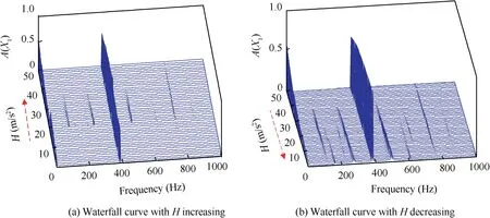
Fig. 11 Waterfall curves of left end of shaft during processes of H increasing and decreasing, with H=0-50 m/s2 and Ω=2390 rad/s(near the first bending critical speed).
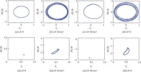
Fig. 12 Evolution of phase diagrams and Poincare´ sections of left end of shaft during processes of H increasing and then decreasing,with H=0-25-40-0 m/s2 and Ω=2390 rad/s (near the first bending critical speed).
Finally, the periodic motion of the left end of the shaft is further studied from the viewpoint of phase diagrams and Poincare´ sections. The phase diagrams and Poincare´ sections during the processes of H increasing and then decreasing,with H=0-25-40-0 m/s2and Ω=2390 rad/s, are shown in Fig.12.Figs. 12(a)-(c) correspond to three kinds of steady responses with the increase of H. We can see that, when H=0(Fig.12(a)),the response of the rotor system is periodic motion and the corresponding Poincare´ section of the response is a focal point. But as H=25 m/s2(Fig. 12(b)), the response jumps into quasi-periodic motion and the corresponding Poincare´ section is a continuous ring. This phenomenon is due to the rise of amplitude shown in Fig. 10(a). Since steady state response of the rotor system jumps from the small amplitude to the big amplitude, the corresponding vibration of the rotor system changes from periodic motion to quasi-periodic motion. When H=40 m/s2(Fig. 12(c)), the response returns to periodic vibration again and the corresponding Poincare´section is a focal point. The responses with the decrease of H are corresponding to Figs. 12(c) and (d). We can see that, as the translational normal acceleration returns to H=0(Fig. 12(d)), the response of the rotor system still keeps quasi-periodic motion and never comes back to the original periodic vibration anymore. This demonstrates that, with the increase of H, the response of the rotor system experiences the process of periodic,quasi-periodic and then periodic vibration. However, with the decrease of H, it is obvious that the response of the rotor system goes through periodic and then quasi-periodic vibration and does not come back to the original periodic vibration anymore. This process is corresponding to the waterfall curves shown in Fig. 11.
In summary, about the effect of aircraft’s translational motion, we can come to the following conclusions. Due to the coupled effects among the rotor, ball bearings and SFDs,within the first bending resonance region, the responses of the rotor show obvious nonlinear characteristics such as bistable phenomenon, amplitude jumping phenomenon and non-synchronous vibration. At the same time, translational acceleration motion of the aircraft will lead to axis offset of the rotor system and thus result in the reduction and the final disappearance of the bistable phenomenon speed within the whole rotating speed region. In addition, when the rotating speed is within the first bending critical resonance region,during the process of the translational acceleration first increasing and then decreasing, amplitude of the rotor jumps from the small amplitude to the big amplitude, and the response of the rotor system experiences the process of periodic, quasiperiodic, periodic and quasi-periodic vibration.
4.2. Effect of aircraft’s angular motion
In this section, the effect of the aircraft’s angular motion on dynamic behavior of the asymmetric rotor system is investigated. Here, pure pitching angular motion is chosen as the examples for illustration. The process of the pitching angular motion includes: steady flight at first, entering into pitching angular motion at t=1 s, and quitting pitching angular motion at t=1.2 s. The pitching angular motion is set to ˙θby=5 rad/s and the translational motion of the aircraft is not considered.
In the first place, the transient time histories of the asymmetric rotor system are studied. The displacement time histories of the disk in θx- and y-direction, under Ω=1000 rad/s(away from the resonance region) and Ω=540 rad/s (within the first order critical resonance region), are chosen as the examples for illustration. They are shown in Fig. 13 and Fig. 14, respectively.
As shown in Fig. 13, pitching angular velocity of the aircraft can lead to the displacement offset of the rotor system in θx- and y-direction. When the rotation speed is at 1000 rad/s (away from the resonance region), the start and the end of the pitching angular velocity can cause transient large amplitude and a long attenuation vibration of the rotor system. The transient largest transverse amplitude caused by pitching angular motion is 96.1 μm which is almost twice as much as the steady transverse amplitude 47.3 μm (Fig. 13(b)).And the attenuation period of the transient vibration lasts approximately 30 ms.
From Fig.14,we can see that when the rotation speed is at 540 rad/s (within the first order critical resonance region), the transient largest transverse amplitude caused by pitching angular velocity is 287.5 μm which is similar to the steady transverse amplitude 252.3 μm(Fig.14(b)).And the attenuation period of the transient vibration lasts approximately 5 ms.By comparing Fig. 14 with Fig. 13, it means that transient vibration caused by transient pitching angular motion could be suppressed better in the critical resonance region. This happens because the damping effect of SFD is directly related to the oil film thickness.That is to say,when the aircraft maneuvers,the larger the displacement of rotor system is,the stronger the suppression of SFD can be.
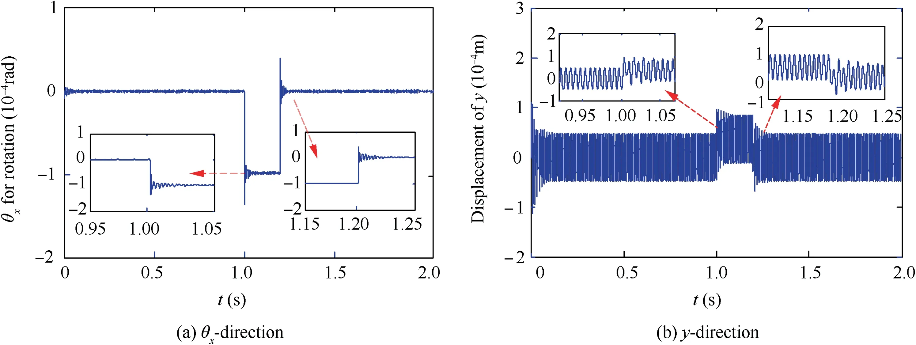
Fig. 13 Transient displacement time history of rotating disk with Ω=1000 rad/s (away from resonance region) and θ˙by (t )=0 (t ∈[0 ,1 s]∪[1 .2 s, 2 s]), θ˙by (t )=5 rad/s (t ∈ (1 s, 1.2 s)).
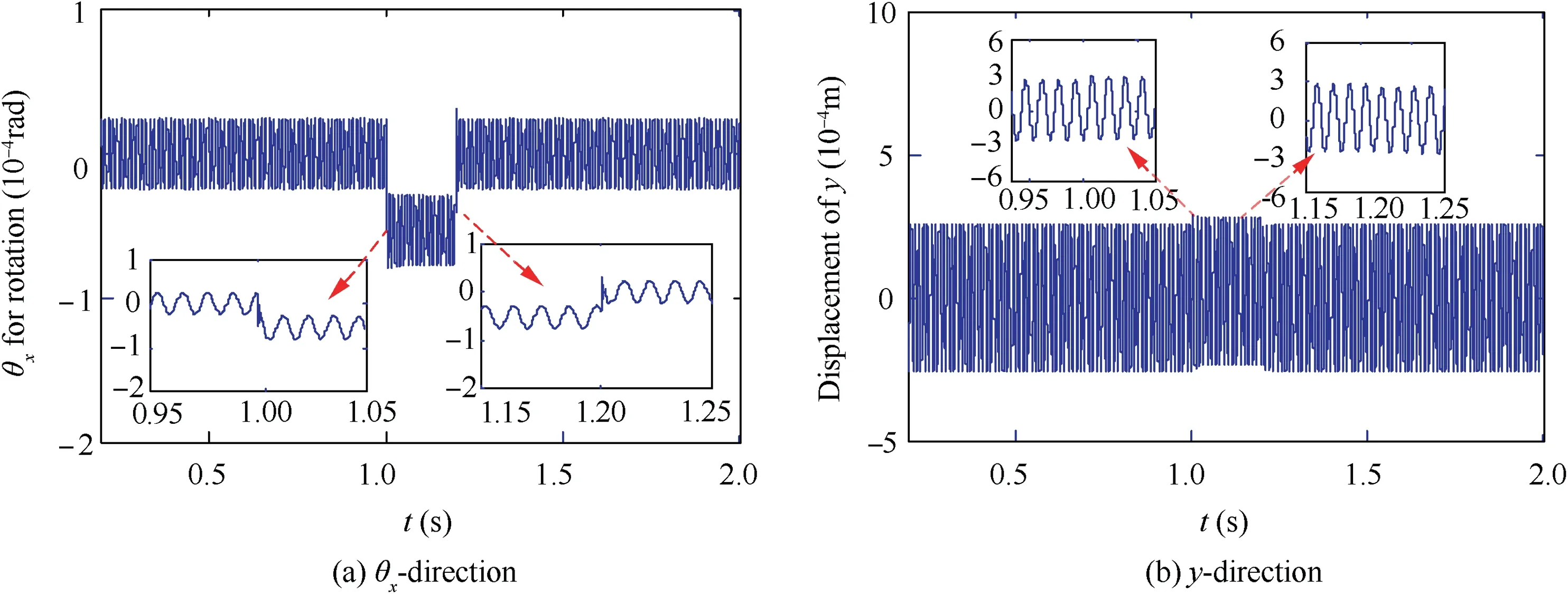
Fig. 14 Transient displacement time history of rotating disk with Ω=540 rad/s (within the first order critical resonance region) and θ˙by ( t)=0 (t ∈ [0 , 1 s]∪[1 .2 s,2 s]), θ˙by (t )=5 rad/s (t ∈ (1 s, 1.2 s)).
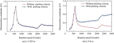
Fig.15 Transverse amplitude-rotating speed curves of rotating disk during aircraft’s steady flight(˙θby =0)and pitching angular motion(˙θby =5 rad/s).
In the second place,transverse vibration of the asymmetric rotor system is investigated considering the pitching angular motion and varied deflection of the rotating disk l1(distance between the disk and the left end of the shaft defined in Fig.2).The responses of the rotating disk in y-direction,under ˙θby=5 rad/s and ˙θby=0,are chosen as the examples for illustration. The transverse amplitude-rotation speed curves for l1=1.025 m, 0.8 m are given in Fig. 15(a) and (b), respectively. The total length of the shaft is a constant and it is l=2.05 m. Hereinto, the curves with red dots denote the transverse amplitude without aircraft’s pitching angular velocity (˙θby=0) and the curves with blue circles denote the transverse amplitude with aircraft’s pitching angular velocity(˙θby=5 rad/s).As shown in Fig.15(a),when the rotor is symmetric (i.e., l1=1.025 m), the transverse amplitudes of the disk with pitching angular velocity are coincident with those without pitching velocity. But when the rotor is asymmetric(l1=0.8 m), the transverse amplitudes of the disk with pitching angular velocity are much bigger than those without pitching velocity.
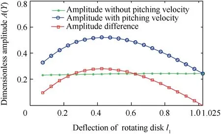
Fig. 16 Transverse amplitude and corresponding difference versus deflection of rotating disk with ˙θby =0 (without pitching velocity) and 5 rad/s (with pitching velocity), l1=0.075-1.025 m and Ω=1000 rad/s.
The overall variation trend of the transverse vibration with varied deflection of the rotating disk (l1=0.075-1.025 m) is further shown in Fig. 16. The curves with green dots denote the transverse amplitude without aircraft’s pitching angular velocity(˙θby=0),the curves with blue circles denote the transverse amplitude with aircraft’s pitching angular velocity(˙θby=5 rad/s) and the curves with red squares denote the difference between the above two kinds of transverse amplitudes.From Fig. 16, we can see that, when the rotor is symmetric(i.e., l1=1.025 m), the transverse amplitudes of the disk with pitching angular velocity are coincident with that without pitching velocity.And as the deflection of the rotating disk gets larger (l1getting smaller), the transverse amplitude, caused by pitching angular velocity, goes through the process of first increasing and then decreasing. According to Eq. (22), aircraft’s pitching angular velocity mainly induces additional gyroscopic moment JpΩ˙θby, which directly affects the rotational vibration of the rotating disk. When the disk is in the middle of the shaft, because the coupled stiffness term krφ=3EIl(l1-l2)/l21l22of the rotating shaft is equal to 0, the pitching angular motion has little effect on the transverse vibration of the rotor system. But with the deflection of the rotating disk getting bigger,the pitching angular motion of aircraft has much greater effect on the transverse vibration of the rotor system because of the enhancement of coupled stiffness term krφof the rotating shaft. However, with the deflection of the rotating disk continuing increasing, the increase of the shaft stiffness krrand krφbecome the main influencing components, and the transverse amplitude, caused by pitching angular velocity, begins to get smaller.
In short, about the effects of the aircraft’s angular motion,we could have the following conclusions. Within the critical resonance region, transient response of the rotor system,caused by the angular motion, could be effectively suppressed by the SFD. At the same time, the pitching angular motion mainly affects rotational vibration of the rotor system, thus further inducing their transverse vibration. In addition, when the rotor system is symmetric, the pitching angular motion has little effect on its transverse vibration. However, as the deflection of the rotating disk gets larger (l1getting smaller),the transverse amplitude, caused by pitching angular velocity,goes through the process of first increasing and then decreasing.
4.3. Transient responses of rotor system during pitching flight with combined translational and angular motions
In this section, transient responses of the rotor system during the pitching flight with combined translational and angular motions are studied. For illustration, flight parameters of the aircraft are chosen as

To be specific, at first (t ∈0, 2 s[ )) the aircraft keeps the steady-state flight (¨Xb=0 and ˙θby=0) and it enters into the pitching flight with combined translational and angular motions at t=2 s and quits the pitching flight at t=2.4 s(Eq. (24)). Then, it returns to the steady-state flight again(¨Xb=0 and ˙θby=0).
In the first place, transient displacement time histories of the left end of the shaft in x- and y-direction are investigated.Here, the parameters t ∈[1 .8 s, 2.8 s], H=18 and 19 m/s2and Ω=2390 rad/s (near the first bending critical speed) are utilized for illustration. The related results are shown in Fig. 17 and Fig. 18, respectively.
From Fig. 17, it can be observed that, when H=18 m/s2,the transient amplitudes of the left end of the shaft in x- and y-direction get bigger during the pitching flight. But after the pitching flight, the vibration returns to the original state. This signifies that, when H=18 m/s2, the pitching flight only results in the transient response of the rotor system temporarily but has no effect on the stability of the rotor response.
When H increases to 19 m/s2(Fig. 18), it is also obvious that the transient amplitudes of the left end of the shaft in xand y-direction get bigger during the maneuvering flight.However, after the pitching flight, unlike that for H=18 m/s2(Fig. 17), the vibration of rotor system does not return to the original state but still keeps the larger steady state response as that during the pitching flight. To some extent, it can be concluded that for the pitching flight studied here,H=19 m/s2could be a critical parameter which is corresponding to the conversion of two steady responses.The transient results obtained here are consistent with the steady state results shown in Section 4.1.2.
In the second place, the time-frequency waterfall curves of the left end of the shaft with t ∈0, 4 s[ ] (Eq. (24)), H=18,19 m/s2and Ω=2390 rad/s are studied. They are shown in Figs.19(a)and(b), respectively.As shown in Fig.19(a),when H=18 m/s2, the response of the rotor system is synchronous vibration before and after the pitching flight.During the pitching flight, although the rotor system shows low-frequency response, there is no harmonic component in the responses.However, when H increases to 19 m/s2, as shown in Fig. 19(b),the harmonic components are aroused during the pitching flight. And after the pitching flight, the response of the rotor system jumps into nonsynchronous vibration state, where the rotor system keeps multi-frequency response.
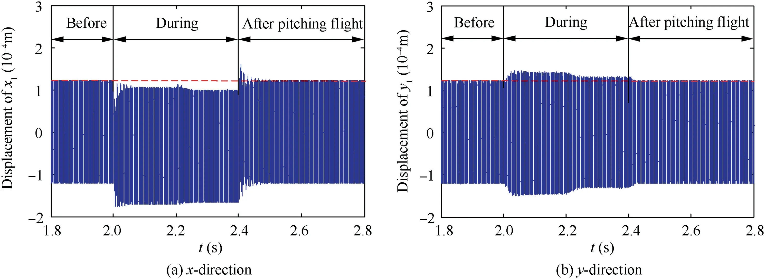
Fig. 17 Transient displacement time history of left end of shaft with flight parameters t ∈[1 .8 s, 2.8 s] (Eq. (24)), H=18 m/s2 and Ω=2390 rad/s (near the first bending critical speed).
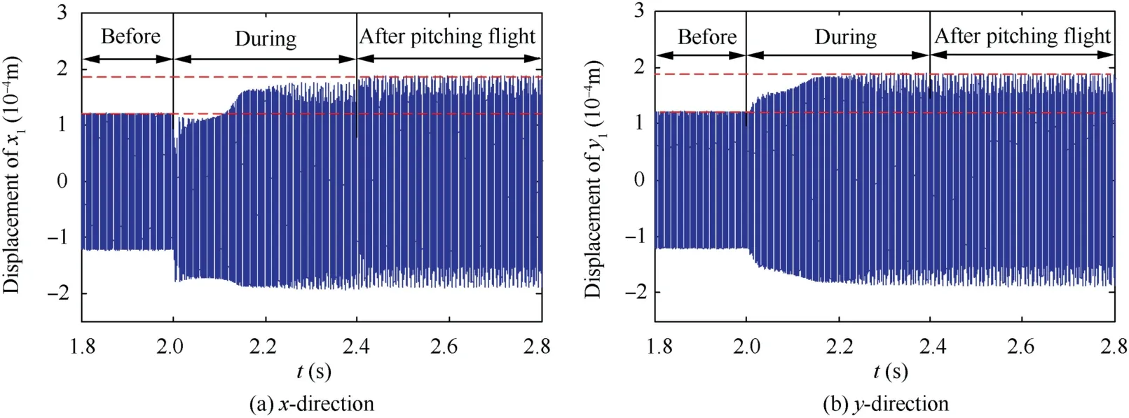
Fig.18 Transient displacement time history of left end of shaft with flight parameters t ∈[1 .8 s, 2.8 s],H=19 m/s2 and Ω=2390 rad/s(near the first bending critical speed).
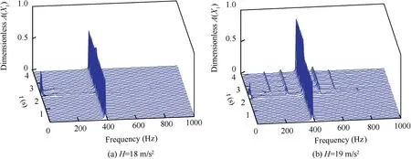
Fig. 19 Time-frequency waterfall curves of left end of shaft with t ∈0,4 s[ ] (Eq. (24)), Ω=2390 rad/s (near the first bending critical speed), H=18 and 19 m/s2.
Finally,the axis trajectories of the left end of the shaft(corresponding to Fig.17 and Fig.18,respectively) before, during and after the maneuvering flight are investigated. They are shown in Fig. 20 and Fig. 21, respectively. By comparing Fig. 20 with Fig. 21, it can be concluded that, when H is less than 18 m/s2, the transient response, caused by the pitching flight,is suppressed by the squeeze film dampers and it returns to the original periodic vibration after the pitching flight.When H is no less than 19 m/s2, because there is multisolution response (bistable phenomenon) in the first bending region,the rotor system jumps into quasi-periodic motion after the pitching flight and never returns back.

Fig. 20 Axis trajectory curves of left end of shaft corresponding to Fig. 17.

Fig. 21 Axis trajectory curves of left end of shaft corresponding to Fig. 18.
From Fig.6(a),we know that there is bistable phenomenon(two steady state solutions) when the rotating speed of the rotor is near the first bending critical speed. To clearly understand the physical reason for critical flight parameter,the transient phase trajectory of the left end of the shaft is chosen as the examples for illustration. The flight parameters are set to t ∈[2 .4 s, 3 s] (Eq. (24)), H=12, 18, 19 and 25 m/s2and Ω=2390 rad/s. Because the end of the pitching flight is the transient initial state of the steady response of the rotor system, the selected data of the phase trajectory begins at t=2.4 s (the end of the pitching flight). As shown in Fig. 22, when H is less than 19 m/s2, such as H=12 and 18 m/s2,the transient phase trajectory,caused by the perturbation of the pitching flight, is around the steady state solution with small amplitude. With the responses of the rotor being asymptotically stable, the vibration of the rotor finally shows small amplitude, steady state synchronous motion. However,when H is no less than 19 m/s2, such as H=19 and 25 m/s2,the perturbation of the pitching flight is big enough to make the transient phase trajectory of the rotor system jump into the region of steady state solution with large amplitude. After that, the vibration of the rotor gradually converges to big amplitude, steady state non-synchronous motion.
In short, the effects of the pitching flight with combined translational and angular motions are summarized as follows.Within the first bending resonance speed region, there exists the critical flight parameter.When the flight parameter is smaller than the critical flight parameter, vibrations of the rotor before and after the pitching flight will not change. However,when the flight parameter is larger than the critical flight parameter, before pitching flight the rotor system shows the small amplitude, steady state synchronous vibration and after the pitching flight it shows the big amplitude,steady state nonsynchronous vibration.
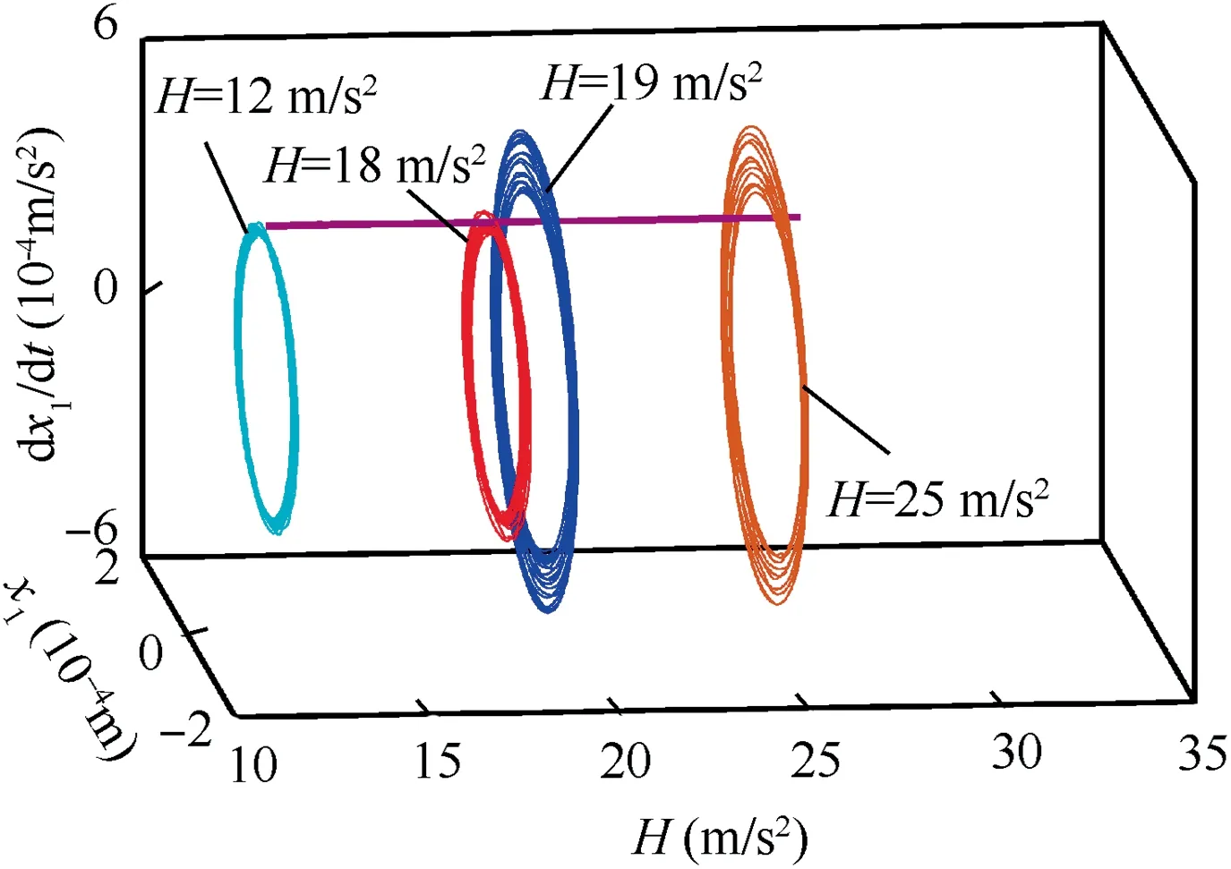
Fig.22 Transient phase trajectory of left end of shaft with flight parameters t ∈[2 .4 s, 3 s] (Eq. (24)), H=12, 18, 19 and 25 m/s2 and Ω=2390 rad/s (near the first bending critical speed).
5. Conclusions
To comprehensively and deeply study the nonlinear dynamic behavior of the aero-engine rotor system supported on ball bearings with SFDs during maneuvering flight,a flexible asymmetric rotor model is established using Lagrange’s equation.Effects of the translational accelerative motions, the angular motions and the pitching flight with combined translational and angular motions on nonlinear dynamic behavior of the aero-engine rotor system are investigated. Some conclusions are drawn as follows:
(1) Due to the nonlinear coupled effects among the rotor,ball bearings and SFDs, within the first bending resonance region, the response of the rotor shows obvious nonlinear characteristics such as bistable phenomenon,amplitude jumping phenomenon and non-synchronous vibration.
(2) Translational acceleration motion of the aircraft will lead to axis offset of the rotor system and thus result in the reduction and the final disappearance of the bistable phenomena within the whole rotating speed region.At the same time, when the rotating speed is within the first bending critical resonance region, during the process of the translational normal acceleration first increasing and then decreasing, the amplitude of the rotor jumps from the small amplitude to the big amplitude, and the response of the rotor system experiences the process of periodic, quasi-periodic, periodic and quasi-periodic vibration.
(3) The pitching angular motion mainly affects the rotational vibration of the rotor system, and thus further induces their transverse vibrations. When the rotor system is symmetric, the pitching angular motion has little effect on its transverse vibration. However, with the deflection of the rotating disk getting larger, the transverse amplitude, caused by pitching angular velocity,goes through the process of first increasing and then decreasing.
(4) Within the first bending resonance speed region, there exists the critical flight parameter. When the flight parameter is smaller than the critical flight parameter,the vibrations of the rotor before and after the maneuvering flight will not change. However, when the flight parameter is larger than the critical flight parameter,before maneuvering flight the rotor system shows the small amplitude, steady state synchronous vibration and after the maneuvering flight it shows the big amplitude, steady state non-synchronous vibration.
Acknowledgements
This work was supported by the National Key Basic Research Program of China(No.2015CB057400),the National Natural Science Foundation of China (Nos. 11672201 and 11872045),and the Major Special Basic Research Projects for Aeroengines and Gas Turbines (No. 2017-IV-0008-0045).
 CHINESE JOURNAL OF AERONAUTICS2020年10期
- CHINESE JOURNAL OF AERONAUTICS的其它文章
- A novel surrogate modeling strategy of the mechanical properties of 3D braided composites
- A user-friendly yield criterion for metals exhibiting tension-compression asymmetry
- Aerodynamic characteristics of morphing wing with flexible leading-edge
- High cycle fatigue failure with radial cracks in gears of aero-engines
- Motion equations of hemispherical resonator and analysis of frequency split caused by slight mass non-uniformity
- Light weight optimization of stratospheric airship envelope based on reliability analysis
