Aerodynamic performance enhancement for flapping airfoils by co-flow jet
To WU, Bifeng SONG, Wenping SONG,b,*, Wenqing YANG,c,Zhonghu HAN
a School of Aeronautics, Northwestern Polytechnical University, Xi’an 710072, China
b Yangtze River Delta Research Institute, Northwestern Polytechnical University, Taicang 215400, China
c Research & Development Institute, Northwestern Polytechnical University in Shenzhen, Shenzhen 518057, China
KEYWORDS Aerodynamic performance;Co-flow jet;Flapping airfoils;Flow control;Propulsive efficiency
Abstract Introducing active flow control into the design of flapping wing is an effective way to enhance its aerodynamic performance. In this paper, a novel active flow control technology called Co-Flow Jet(CFJ)is applied to flapping airfoils.The effect of CFJ on aerodynamic performance of flapping airfoils at low Reynolds number is numerically investigated using Unsteady Reynolds Averaged Navier-Stokes (URANS) simulation with Spalart-Allmaras (SA) turbulence model.Numerical methods are validated by a NACA6415-based CFJ airfoil case and a S809 pitching airfoil case.Then NACA6415 baseline airfoil and NACA6415-based CFJ airfoil with jet-off and jet-on are simulated in flapping motion, with Reynolds number 70,000 and reduced frequency 0.2. As a result,CFJ airfoils with jet-on generally have better lift and thrust characteristics than baseline airfoils and jet-off airfoil when Cμ is greater than 0.04, which results from the CFJ effect of reducing flow separation by injecting high-energy fluid into boundary layer. Besides, typical kinematic and geometric parameters, including the reduced frequency and the positions of the suction and injection slot,are systematically studied to figure out their influence on aerodynamic performance of the CFJ airfoil.And a variable Cμ jet control strategy is proposed to further improve effective propulsive efficiency. Compared with using constant Cμ, an increase of effective propulsive efficiency by 22.6% has been achieved by using prescribed variable Cμ for NACA6415-based CFJ airfoil at frequency 0.2.This study may provide some guidance to performance enhancement for Flapping wing Micro Air Vehicles (FMAV).
1. Introduction
Flapping wing Micro Air Vehicles (FMAV) are expected to revolutionize the way of information retrieval for reconnaissance and monitoring missions due to its distinctive bionic appearance and flight characteristics. The majority of FMAV applications require flexible maneuverability and long cruise duration, and both large aerodynamic force and high aerodynamic efficiency are demanded. How to improve aerodynamic performance and efficiency for FMAV has always been a hot area of research.
Over the past few decades,people found lots of methods to improve the aerodynamic performance of FMAV by studying flapping wing kinematic, morphology and deformation. Neef and Hummel1and Lin and Hu2investigated a 2D airfoil in plunging and pitching motion,found that a maximum propulsive efficiency would be got when the phase shift between pitching motion and plunging motion is close to 90°.Bansmer and Radespiel,3Izraelevitz and Triantafyllou,4Licht et al.5and Esfahani et al.6studied the gliding oscillations of flapping airfoils and demonstrated that a sweeping motion is beneficial for improving thrust and propulsive efficiency.Bahlman et al.7assessed the relationship between mechanical power input and aerodynamic force output across different isolated kinematic parameters of mechanical bat, and they pointed out that retracting the wing during upstroke reduces power requirements and increases net lift production while flapping. Wang et al.8,9carried out numerical simulations on threedimensional plate model and bat-inspired model which can dynamically change wingspan, and they found that the outspread of flapping wing during downstroke significantly intensifies leading-edge vortices on the upper surface which lead to higher efficiency of lift generation. Young et al.10investigated the effects of wing morphology and deformation of locusts,and found that wing camber and twist are very important to power economy. Thielicke and Stamhuis11,12researched the influence of wing morphology on the three-dimensional flow patterns of a flapping wing at bird scale,and provided effective guidance to the wing design of FMAV. Nan et al.13obtained relatively high efficiency wing shape of a flexible wing for a hummingbird-sized FMAV by experimental measurement,and they pointed out that camber angle and aspect ratio have a critical impact on the force production and efficiency enhancement. Heathcote et al.14,15studied the effect of chordwise and spanwise flexibility on the thrust, lift and propulsive efficiency of a heaving rectangular wing by water tunnel experiments,and they concluded that moderate flexibility can benefit thrust coefficient and efficiency.
All of those work helped people to understand the high efficiency flight mechanism of flying animals. Besides, many prototypes have been developed by applying some of those research finding, such as Nano Hummingbird16invented by AeroVironment Inc, Smart Bird17by Festo, Delfly18by Delft University of Technology as well as Dove19by Northwestern Polytechnical University. Till now, great success has been made in FMAV design by mimicking wing motions,morphology as well as deformation of natural flyers.However,the flow patterns between FMAV wing and real bird wings still differ greatly, which become one of major factors limiting the improvement of bird-inspired flapping wing aerodynamic performance. For avian flight, there are many distinctive flow control devices,such as feather roughness,20velvet-like surface structure,21leading-edge serrations22and alula,23being universally adopted to enhance aerodynamic performance by suppressing flow separation during gliding or flapping flight.According to Young et al.10and Thielicke et al.,11attachedflow aerodynamics during insects and birds flapping flight can still offer greater efficiency.However,the lack of auxiliary flow control devices for FMAV makes it relatively hard to realize attached-flow in large angle of attack condition.Hence,it is expected that some effective active flow control techniques will be applied to improve flapping wing surface flow pattern and extend the aerodynamic performance of FMAV.
Zha and Paxton24developed a novel flow control technology called Co-Flow Jet (CFJ), which has been proved to be a useful method to significantly increase lift and reduce drag for stationary airfoils. The co-flow jet airfoil is to open an injection slot near the leading edge and a suction slot near the trailing edge on the airfoil suction surface. A high-energy tangential jet in the same direction of main flow is injected at low pressure portion near the leading edge and the same amount of mass flow is sucked at high pressure portion in near the trailing edge,making it quite easy to form a closed-loop jet circuit.The working mechanism of CFJ is to mix jet with main flow to energize the main flow and overcome the adverse pressure gradient, thus enabling flow on suction surface to remain attached at high angle of attack.25Zha’s team26-29has done pioneering work on CFJ in steady condition through numerical simulation and experimental measurement. Xu et al.30,31and Sun et al.32extended application of CFJ to wind turbine airfoils, and achieved good dynamic stall control effect. Overall, it has been demonstrated that CFJ is an effective active flow control technique to decrease flow separation at large angle of attack, suggesting that it may be a good way to enhance aerodynamic performance of flapping airfoil at Reynolds number of bird size during cruising.
In this paper, CFJ concept is applied to flapping airfoil at low Reynolds number for the first time, and the effect of CFJ on aerodynamic performance of flapping airfoil is numerically investigated in detail. Initially, the CFD solver is validated by two numerical cases. Then, the overall aerodynamic performance of the jet-off and jet-on airfoil is addressed.How jet momentum coefficients influence periodic averaged aerodynamic forces, effective propulsive efficiency as well as flow pattern are further analyzed to explain the CFJ effects on flapping airfoils. Based on this, typical kinematic and geometric parameters, including the reduced frequency and the position of the suction and injection slot, are systematically studied to figure out their influence on aerodynamic performances of the CFJ airfoil. Finally, a variable Cμjet control strategy is proposed to further improve effective propulsive efficiency for flapping airfoil with CFJ active flow control.
2. Methodology
2.1. Numerical methods

Fig. 1 Co-flow jet computational model.
An in-house CFD solver, called ‘‘PMNS2D”,33-36is used in this work. The preconditioned Unsteady Reynolds Averaged Navier-Stokes (URANS) equations are solved based on a Finite Volume Method (FVM) within the framework of an efficient Full Approximation Storage(FAS)multigrid method.The space discretization is a cell-centered finite volume method using central difference, with nearly second-order accuracy on smooth structured grid. A dual time stepping method is adopted for time marching and the LU-SGS scheme is implemented to accelerate the convergence for inner iteration of pseudo-time stepping. SA turbulence model is adopted in this study to close the URANS equations.
A simplified computational model of CFJ airfoil with internal piping and pumps removed, as shown in Fig. 1, is used in this study. Suitable jet velocity boundary conditions are applied to realize co-flow jet active flow control. The flow velocity at injection slot is set as a constant value according to a given jet momentum coefficient, and at the same time the suction slot flow velocity is adjusted to match the mass flow at injection slot.When the co-flow jet is activated,fluid will be injected tangentially into the main flow from injection slot,and the same amount of mass flow will be sucked into the suction slot, forming a closed-loop jet circuit.
2.2. Solver validation
Two validation cases are chosen to evaluate the accuracy of solver- ‘‘PMNS2D”. One is NACA6415-based CFJ case,which is used to prove the rationality of simplified CFJ computational model and the ability of ‘‘PMNS2D” to simulate boundary layer flow under low Mach number and low Reynolds number. The other is an S809 pitching case, which is adopted to assess unsteady flow simulation precision of‘‘PMNS2D”.
2.2.1. CFJ simulation and validation
A NACA6415-based CFJ airfoil from Miami University 24 in×24 in (1 in=25.4 mm) wind tunnel27is selected as the first test case. The flow conditions are freestream Mach number Ma=0.03; the chord-based Reynolds number Re=2.08×10⁵. The CFJ airfoil with jet momentum coefficient Cμ=0.08 at injection slot in experiment is chosen here to validate the flow solver for CFJ simulation. In this flow case, the mesh for CFD simulations is represented in Fig. 2.The grid employed is 280×45 in grid Zone 1, and 593×189 in grid Zone 2; the height of the first cell next to the wall is about 6×10⁻⁶c to make sure y+less than 1.0; the O-type domain radius is 100 times of the chord length.
Fig. 3 shows the comparison of lift coefficient CL, drag coefficient CDand power coefficient Pcfor present CFD simulation, Lefebvre’s CFD simulation37and experimental measurement (EXP). Our calculation results show similar trends compared with Lefebvre’s CFD simulation and experimental data. Regrettably, it needs to be pointed out that the lift coefficient and the drag coefficient of all the CFD simulation perform some differences with measured data under relatively large angle of attack due to the limitation of RANS solver in simulating large separation flow. Overall, it is reliable to use our CFD solver ‘‘PMNS2D” to estimate aerodynamic force coefficients and power coefficient for CFJ airfoils.
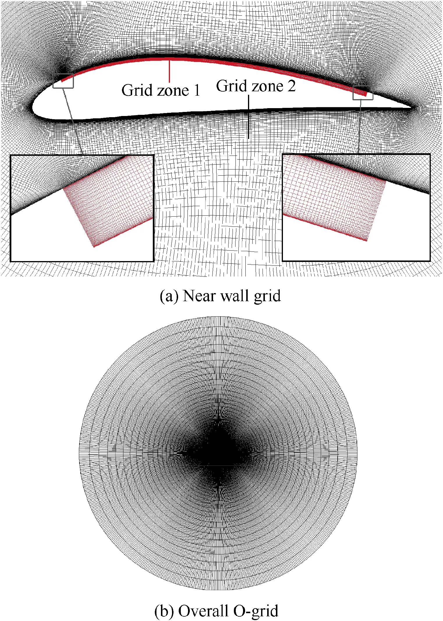
Fig. 2 Grid of NACA6415-based CFJ airfoil.
2.2.2. Dynamic characteristics and validation
The second test case is a S809 airfoil with sinusoidal pitch oscillation from the Ohio State University Aeronautical and Astronautical Research Laboratory (OSU/AARL) 3 ft×5 ft(1 ft=304.8 mm) subsonic wind tunnel experiment.38The flow conditions are listed as follows: Mach number Ma=0.076; the chord-based Reynolds number Re=1.0×10⁶. The kinematic parameters of pitching motion are: mean pitching angle α0=14°, pitching amplitude αm=10°, and reduced frequency κ=0.077. The distribution of the computational mesh in the streamwise direction and wall-normal direction is 581×149, the first grid layer spacing is 5.0×10⁻⁶c, and y+is less than 1.0.
The hysteresis curve of lift coefficient and drag coefficient of numerical simulation are depicted in Fig. 4, which agrees well with experimental results before flow stalls. Hence, it is convincing to use the present solver to predict unsteady aerodynamic characteristics of flapping airfoils.
3. Numerical study of CFJ effect on flapping airfoil
3.1. Flapping motion
The kinematic of flapping airfoil combines a plunging motion and a pitching motion about quarter chord point,as shown in Fig. 5. The kinematic equations of different motions are defined as
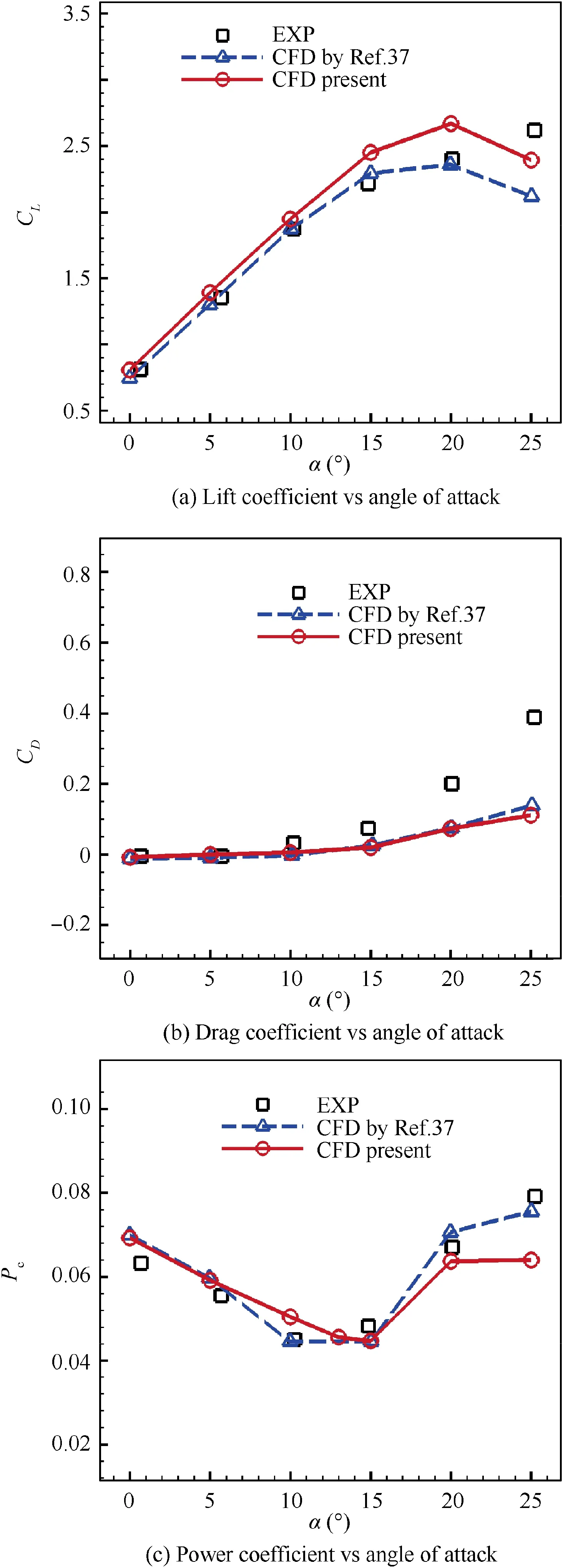
Fig.3 Comparison of lift coefficient,drag coefficient and power coefficient between experiment and CFD simulations for NACA6415-based CFJ airfoil.
where z(t) is the vertical position at time t, zmis the plunging amplitude,α(t)is the pitching angle with respect to the horizon at time t, α0is the mean pitching angle, and αmis the pitching amplitude. The radial frequency of the motion is given as ω=2πf, and f represents flapping frequency. Furthermore,φ is the phase shift between plunging motion and pitching motion. For flapping airfoils, the reduced frequency κ is usually used to describe the unsteady motion, which is defined as Eq. (2), where c is the chord length, and U∞is the velocity of the freestream.Detailed kinematic parameters’value used in this study are listed in Table 1.
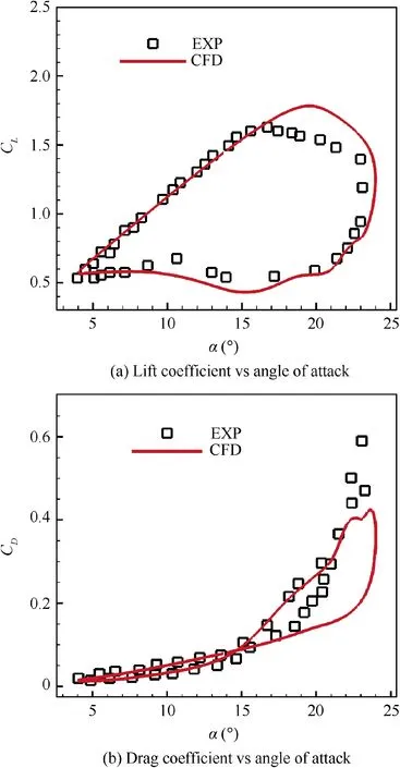
Fig. 4 Comparison of lift and drag coefficient loops between experiment and CFD simulations for S809 airfoil.
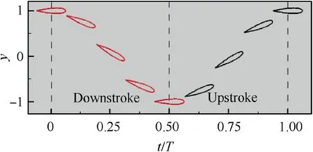
Fig. 5 Temporal position of flapping airfoil during downstroke and upstroke.

The effective angle of attack αeffis introduced to study the flapping process of the airfoil, which is highly correlated to flow separation. As shown in Fig. 6, αeffis the angle between the airfoils chord line and resultant flow velocity, which is defined as

Table 1 Kinematic parameters of flapping motion.
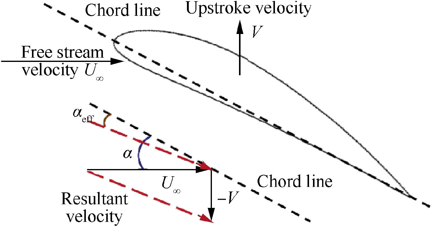
Fig. 6 Effective angle of attack.

3.2. Relevant parameters in CFJ airfoil simulation at flapping motion
The jet momentum coefficient Cμis a parameter used to quantify the jet intensity.It is defined as Eq.(4),where ˙mjis the coflow jet mass flow rate,Vjis the injection jet velocity,ρ∞is the free stream density, and S is equal to chord length c for twodimensional cases.

For a CFJ airfoil, the jet reaction force must be included when calculating lift and thrust of airfoil. In the simplified model shown in Fig. 1, the force acting on the airfoil comes from three components: surface pressure, surface shear stress and jet reaction force. Hence, the calculation formula of time averaged lift coefficient and thrust coefficient during a cycle can be presented as

where subscript ‘‘pressure” represents the contribution of airfoil integral surface pressure to force coefficient; subscript‘‘stress” represents the contribution of airfoil integral surface shear stress to force coefficient; subscript ‘‘jet” represents the contribution of jet reaction to force coefficient.
One of salient features of active flow control is the additional energy expenditure.In CFJ concept,the power required to pump jet is determined by the jet mass flow rate and total pressure ratio to overcome the total pressure loss of the recirculated jet flow. And it is usually described by a nondimensional similarity parameter called power coefficient Pc.For moving airfoils, a periodic averaged power coefficient can be defined as

where cpis the specific heat at constant pressure, ηpis the pump efficiency (ηp=1.0 is used in this study, which is relatively an ideal condition), P01is the total pressure at suction slot, P02is the total pressure at injection slot, and T01is the total temperature at suction slot.
Generally, the propulsive efficiency39of the flapping airfoil is defined as
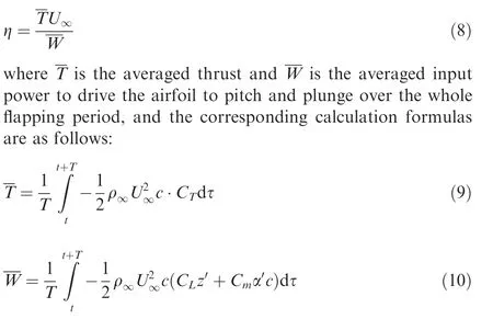
For CFJ airfoils, an additional power consumption caused by jet cycling must be taken into consideration while estimating propulsive efficiency.Referring to the definition of effective lift to drag ratio in Ref.37an effective propulsive efficiency ηeis introduced in this paper, which can be calculated by

3.3. Convergence study of grid size and time resolution
NACA6415 airfoil is adopted as the baseline airfoil in this study. The flow conditions are free stream velocity U∞=10 m/s, Reynolds number Re=70,000, which are quite similar to that of a pigeon’s flight during cruising.In this part,different grid size and time steps are adopted to choose suitable mesh scale and time step for good accuracy of numericalsimulation. The kinematic parameters of flapping motion shown in Table 1 with κ=0.2 are adopted.

Table 2 Parameters of different grid employed for NACA6415 baseline airfoil.
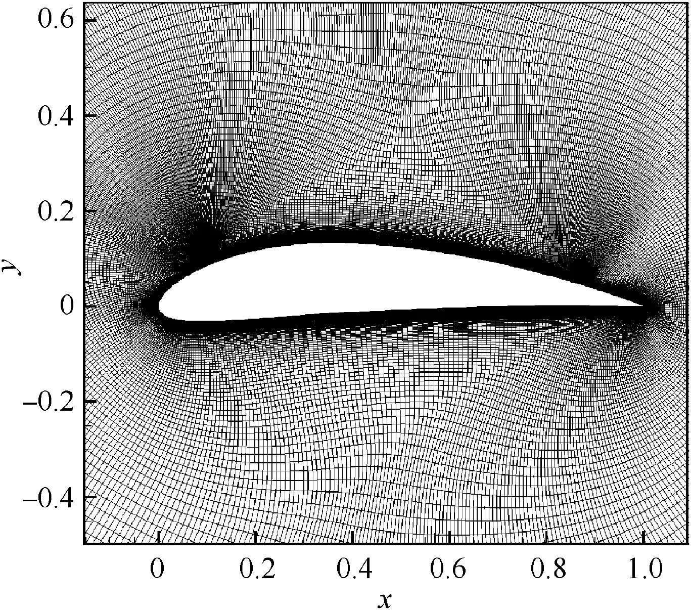
Fig. 7 Medium level O-mesh for NACA6415 baseline airfoil.

Table 3 Time averaged aerodynamic coefficients for different mesh levels.
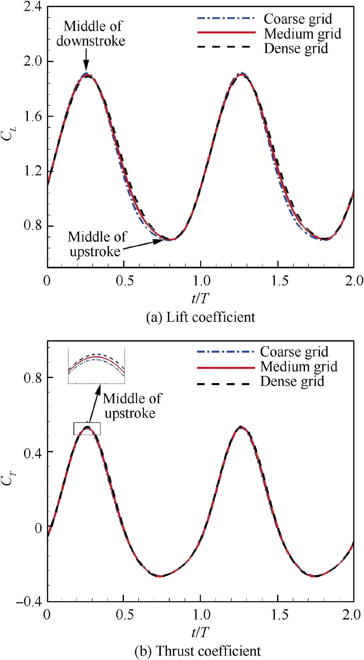
Fig.8 Instantaneous lift coefficient and thrust coefficient during the twelfth and thirteenth cycle for different grid size.
3.3.1. Grid resolution study
A convergence study of grid size was carried out over three meshes. Detailed kinematic parameters employed for different grid size are presented in Table 2,and a medium level O-mesh for NACA6415 baseline airfoil is shown in Fig. 7.
Table 3 shows the time averaged lift coefficient, drag coefficient and moment coefficient obtained for three mesh levels.The averaged drag and moment coefficient are quite close between medium grid and dense grid, showing good grid size convergence.
Instantaneous lift coefficient and thrust coefficient during the twelfth and thirteenth cycle for different grid size are shown in Fig. 8. The computational results from coarse grid deviate slightly from those of other two grids while the results of medium grid are almost the same with those of dense grid,indicating that grid independence has been achieved between medium grid and dense grid. Therefore, the medium grid with a size of 593×189 is chosen for subsequent computations.
3.3.2. Time resolution study
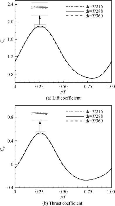
Fig.9 Instantaneous lift coefficient and thrust coefficient during the ninth and tenth cycle for different time steps.
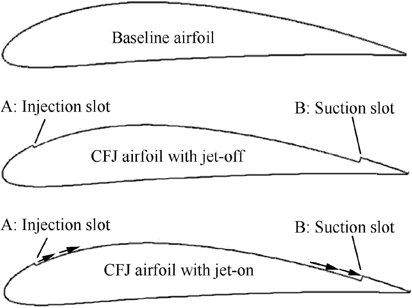
Fig. 10 Configuration of NACA6415 baseline airfoil,NACA6415-based CFJ airfoil with jet-off and jet-on.
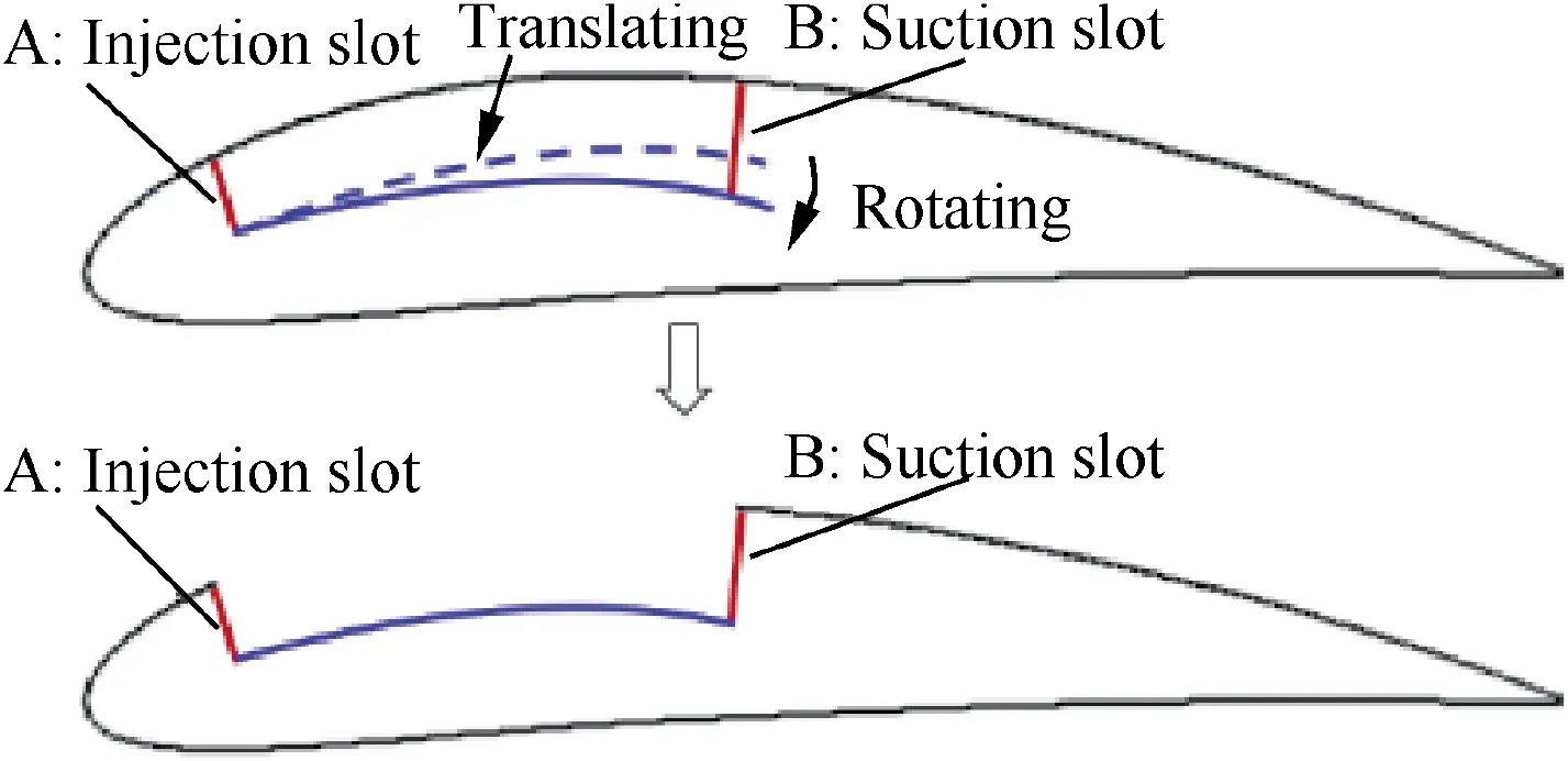
Fig. 11 Shaping surface between injection and suction.
The time step sensitivity test is carried out over medium mesh of NACA6415 baseline airfoil with flapping motion.Unsteady simulation is performed with a flapping cycle divided into 216,288 and 360 time steps.Each case is calculated for 10 cycles to ensure convergence of results. Instantaneous lift coefficient and thrust coefficient during the tenth cycle for different time steps are shown in Fig. 9. It is obvious that force coefficients have little differences among three different time steps. Good time resolution can be achieved with 288 time steps in a flapping cycle. Hence, a number of 288 time steps during a cycle is adopted to carry out all the subsequent calculations for both the jet-off and jet-on configurations.
3.4. Jet-off and jet-on airfoil simulation
3.4.1. Jet-off airfoil simulation
Co-flow jet flow control concept has a distinct feature that a jet channel is implemented to a large portion of the airfoil suction surface, which greatly changes the shape of baseline airfoil, as shown in Fig. 10. Therefore, a jet-off configuration is simulated at the same conditions as the baseline airfoil with flapping motion, in order to study the influence of jet channel on the dynamic aerodynamic characteristics of flapping airfoil.The injection and suction device are located at 7.5% and 88.5% of chord on upper surface with slot heights 0.65%and 1.42%of the chord length respectively,which are referred to in Ref27. The surface between injection and suction is obtained by translating and rotating the corresponding upper surface of baseline airfoil, as shown in Fig. 11.
The instantaneous force coefficients for baseline and jet-off airfoil during a flapping cycle are shown in Fig.12.The jet-off case has an overall lower lift coefficient than baseline airfoil.Velocity contours and streamlines at the beginning of downstroke, middle of downstroke, end of downstroke and middle of upstroke for both baseline airfoil and jet-off airfoil are shown in Fig. 13. It can be seen that the existence of channel in jet-off airfoil leads to wider flow area along upper surface of airfoil,which apparently slows down the fluid on upper surface. Accordingly, relatively larger trialing edge separation on upper surface appears during all the flapping cycle for jet-off airfoil, which leads to a lower lift coefficient.
It can be observed in Fig.12 that the baseline airfoil generally has higher transient thrust coefficient than the jet-off airfoil through the flapping cycle. During the whole downstroke,flow velocity of fluid on upper surface for baseline airfoil is larger than that for jet-off airfoil, which leads to relatively greater leading-edge suction for baseline airfoil.Besides, smaller trailing edge flow separation for baseline airfoil can also effectively reduce pressure drag.Therefore,larger thrust coefficient is achieved for baseline airfoil during downstroke. At the middle of upstroke, the acceleration of fluid on upper surface for baseline airfoil is still stronger and trailing edge flow separation portion is still smaller than that for jet-off airfoil, which is quite similar to those at the middle of downstroke. However, the effective incoming flow direction in this moment is greatly changed compared with that at the middle of downstroke due to the reverse of flapping direction (depicted in Fig.13),which significantly influences the production of thrust.It is obvious that the faster fluid on upper surface for baseline will cause relatively lower pressure on suction surface than that for jet-off airfoil, which is devoted to a larger drag for baseline airfoil at the middle of upstroke.
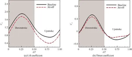
Fig. 12 Instantaneous lift coefficient and thrust coefficient of baseline and jet-off airfoil during a cycle.
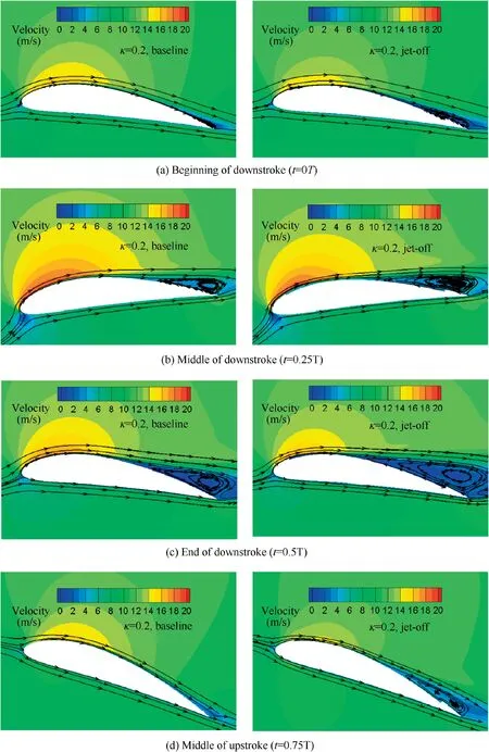
Fig. 13 Velocity contour and streamline of baseline airfoil and jet-off airfoil.
Table 4 shows the results of periodic averaged lift coefficient, thrust coefficient as well as propulsive efficiency for jet-off airfoil and baseline airfoil. There are 16.8% lift decrease,9.2%thrust decrease and 20.0%propulsive efficiency decrease for jet-off airfoil compared with baseline airfoil.Therefore, the existence of jet channel deteriorates aerodynamic performance of baseline airfoil when the co-flow jet is inactive.

Table 4 Comparison of averaged force coefficients during a cycle between baseline and jet-off airfoil.
3.4.2. Jet-on airfoil simulation
As the main focus of the present study,the dynamic characteristics of NACA6415-based CFJ airfoil are investigated with different momentum coefficient Cμ. The CFD mesh for NACA6415-based CFJ airfoil is shown in Fig. 14, which places an additional jet channel mesh to the baseline mesh of medium grid size.
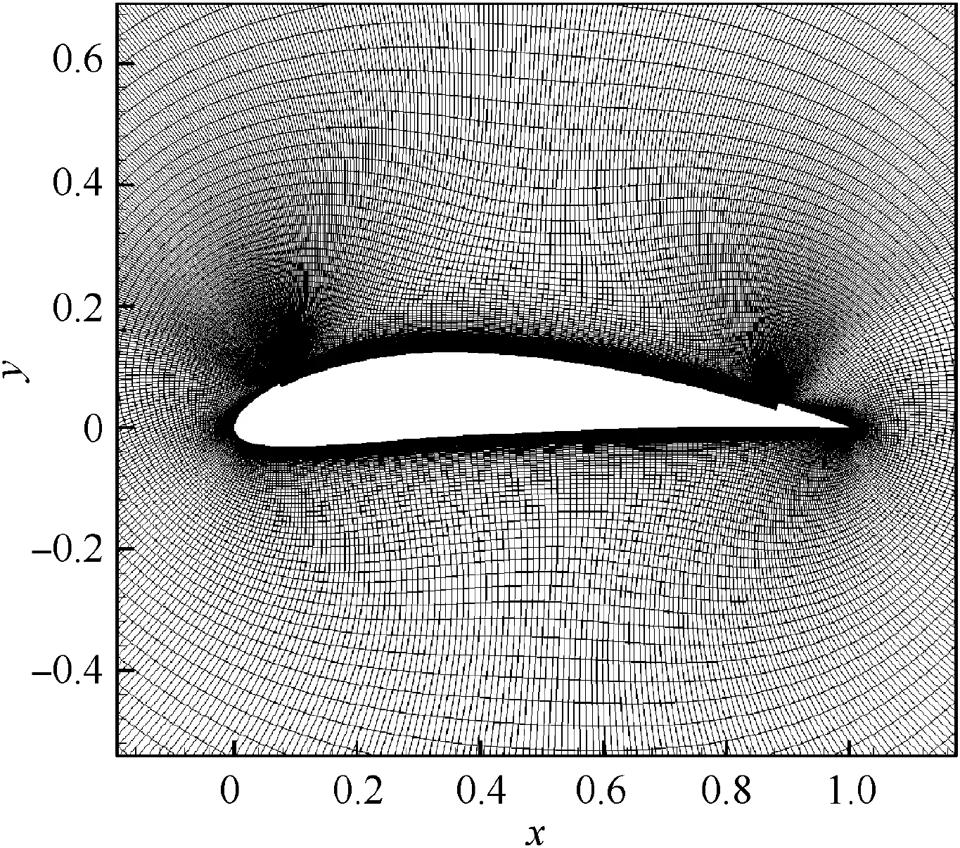
Fig. 14 O-mesh for NACA6415-based CFJ airfoil.
The simulation results are shown in Fig.15,and time averaged lift coefficient, drag coefficient, total power coefficient and effective propulsive efficiency are all included.It is obvious that Cμhas significant influence on the aerodynamic performance of the CFJ airfoil. When Cμis greater than 0.04, the jet-on airfoil can achieve higher lift coefficient and thrust coefficient compared with the baseline airfoil and jet-off airfoil.When CFJ is active(Cμ>0.02 in present study),the averaged lift and thrust coefficients firstly grow rapidly and then slowly with the increase of Cμ, showing a great potential for aerodynamic force enhancement.Besides,the effective propulsive efficiency reaches its maximum value 0.439 when Cμ=0.08,which is much higher than that of jet-off airfoil.
For the cost of CFJ airfoil, it consumes much more energy compared with the baseline and jet-off airfoil. As shown in Fig. 16, the power consumption for driving airfoil moving(Cp) slightly decreases with Cμgrowing. However, the power consumption for driving jet cycling (Pc) remarkably increases as Cμchanges from 0.02 to 0.14. As a result, the total power coefficient (Cw) rises up with the increase of Cμ.
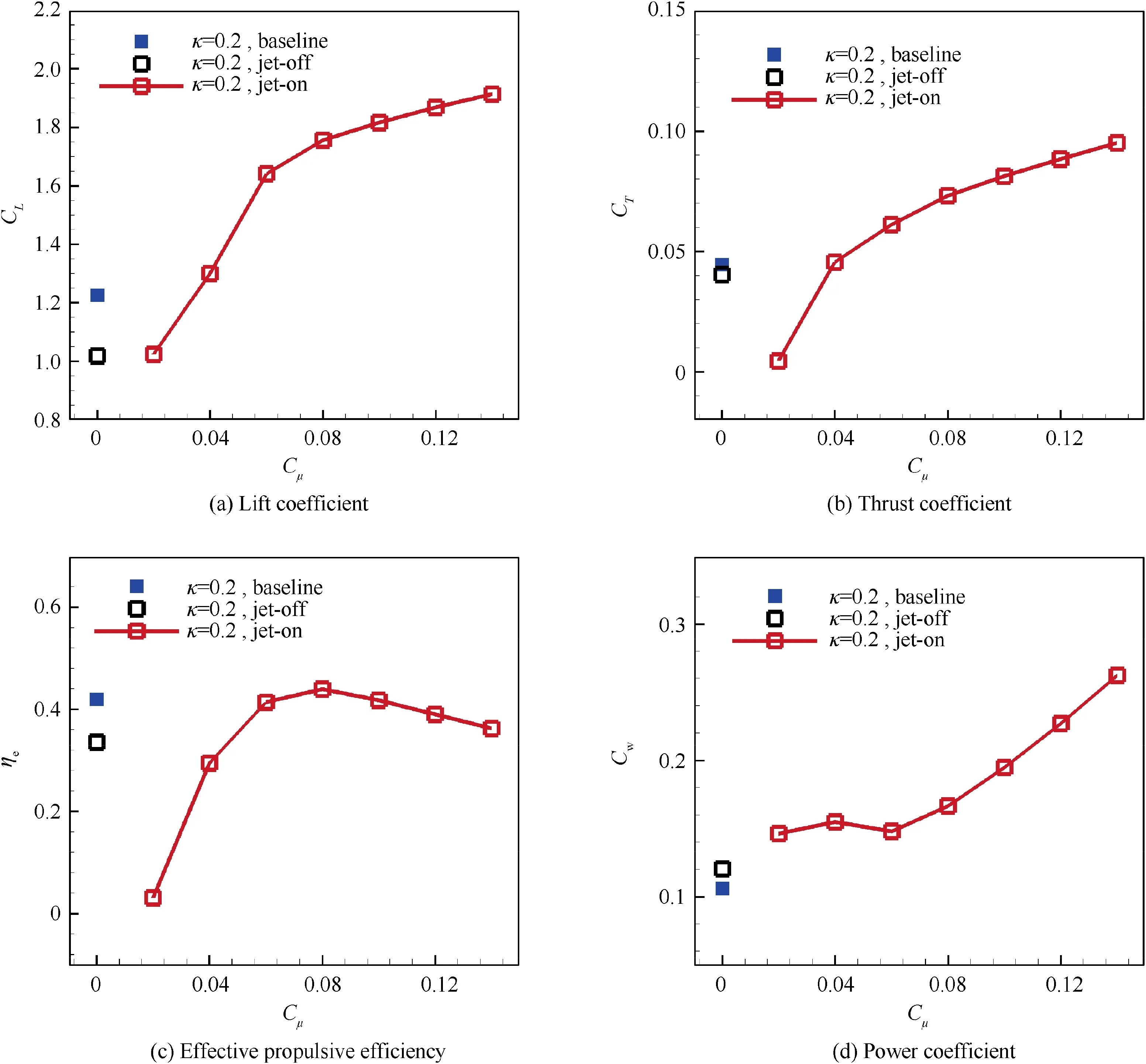
Fig. 15 Variation of time averaged lift coefficient, thrust coefficient, effective propulsive efficiency and total power coefficient with different jet momentum coefficient for CFJ airfoil.
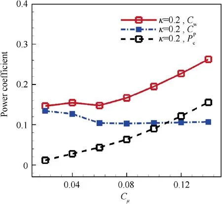
Fig. 16 Comparison of time averaged power coefficient at different Cμ levels.
Fig.17 presents transient pressure coefficient distribution of baseline airfoils and CFJ airfoils under different Cμat the beginning of downstroke,middle of downstroke,end of downstroke and middle of upstroke. As jet momentum coefficient Cμincreases, a stronger jet is injected into the main flow,and the mixing between high-energy jet and main flow effectively accelerates the main flow in large portion of airfoil upper surface, which causes strongly negative pressure on the upper surface and thus leads to enhancement of lift coefficient. In addition, the leading-edge stagnation point on the lower surface of the CFJ airfoil moves backward when the jet momentum coefficient increases,meaning that actual effective angle of attack becomes large,which also contributes to the increase of the lift coefficient.
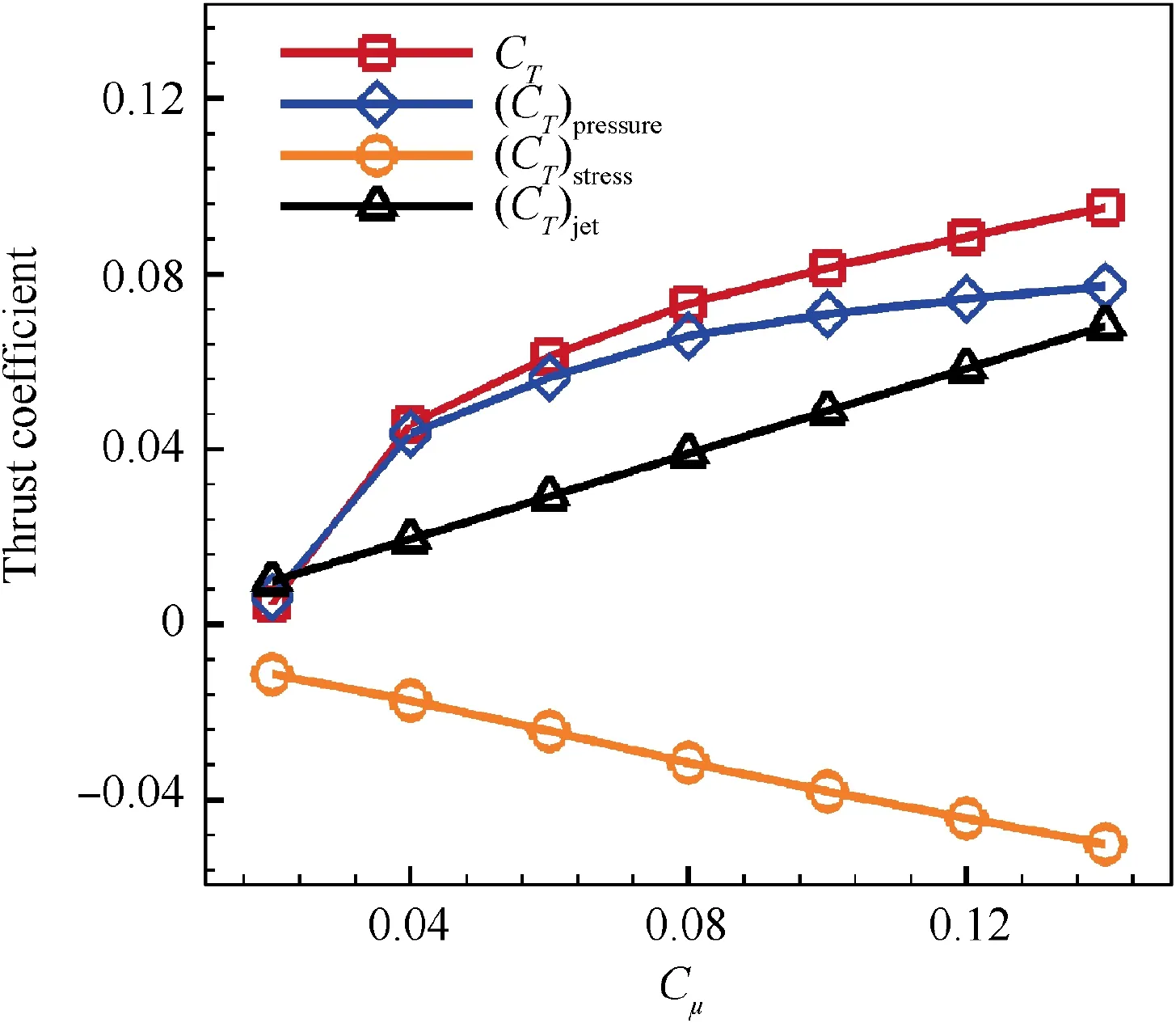
Fig. 18 Change of time average thrust coefficient and its components with various jet momentum coefficient.
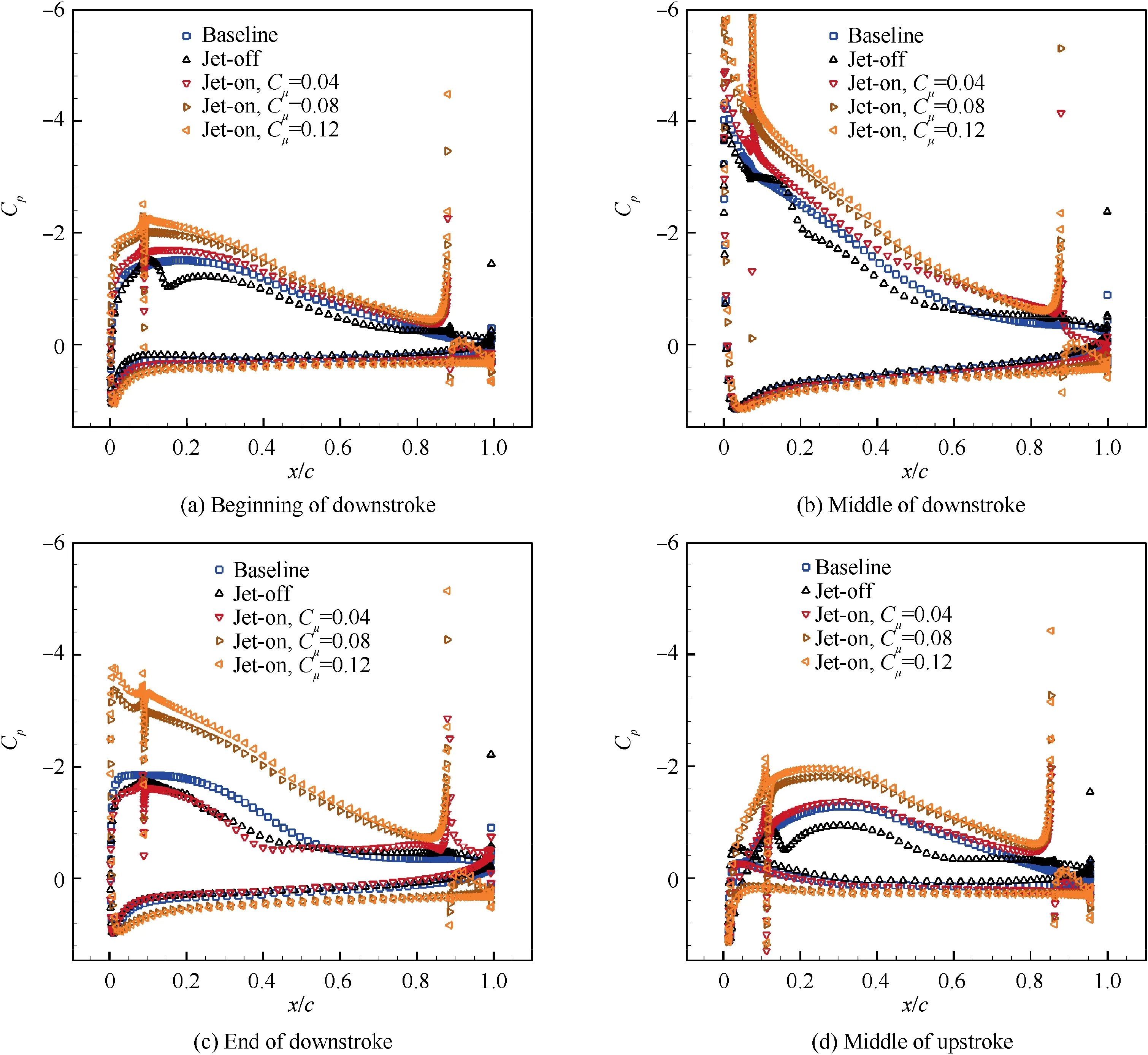
Fig. 17 Pressure coefficient distribution for baseline airfoil and CFJ airfoil with different Cμ at different flapping position.
In order to figure out the influence of Cμon thrust,the time averaged thrust coefficient is divided into three components as depicted in Fig. 18, including jet contribution (CT)jet,shear stress contribution (CT)stressand pressure contribution(CT)pressure. (CT)jetand (CT)pressurecontribute to thrust enhancement at different Cμ, while (CT)stresshas an opposite effect. It is clearly observed that the variation of thrust coefficient CTwith Cμis dominated by (CT)pressure.
Velocity contour and streamline under different jet momentum coefficients of CFJ airfoil at the beginning, middle and end of downstroke as well as middle of upstroke are shown in Fig. 19. With the growth of Cμ, the acceleration of fluid on upper surface causes larger negative pressure peak near the airfoil leading edge, which can produce stronger leading-edge suction to boost thrust generation during downstroke. Moreover, the increase of jet momentum coefficient also strengthens the ability of boundary layer to resist adverse pressure gradient, which makes the flow separation smaller on trailing edge of the upper surface and thus reduces pressure drag during whole cycle. As a result, the(CT)pressurecontinuously increases when Cμbecomes larger.As the momentum coefficient of jet increases, the momentum of flow around the inlet and outlet increases, and therefore greater jet reaction force will be produced for CFJ airfoil. Meanwhile, a higher normal velocity gradient near wall is produced due to high-energy jet, which increases surface friction. Overall, the thrust improvement devoted by(CT)jetis counteracted by (CT)stress, and the greater promotion in (CT)pressureeffectively increased the total thrust when Cμis growing.
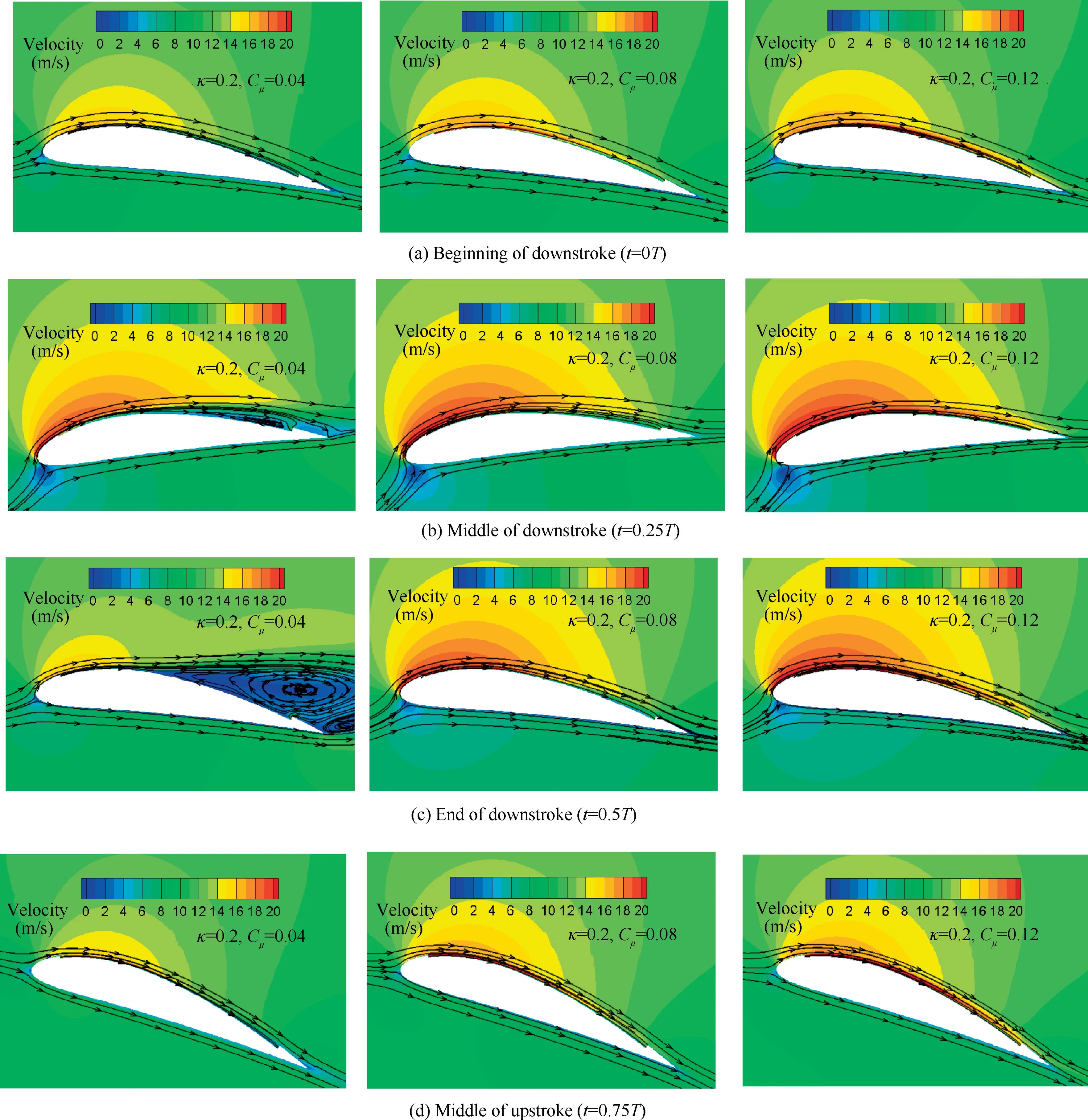
Fig. 19 Velocity contour and streamline under different momentum coefficients of CFJ airfoil.
The effective propulsive efficiency reaches its maximum value 0.439 at Cμ=0.08, which is 31.0% higher than that of jet-off airfoil. The flow fields at t=0.42 T under different momentum coefficients of CFJ airfoil are presented in Fig. 20. It should be pointed out emphatically that 0.42 T is the moment when maximum flow separation occurs in those simulation. When Cμequals 0.02, there are two large vortexes on upper surface on CFJ airfoil. With the increase of Cμ, the vortexes become smaller, and eventually disappear when Cμis great than 0.08. This means that a minimum constant momentum coefficient value of 0.08 is required to suppress flow separation during the whole flapping cycle. When Cμis less than 0.08, it is not sufficient to suppress flow separation all the time, thus leading to relatively larger pressure drag and smaller effective propulsive efficiency. It is obvious that total power coefficient remarkably increases from Cμ=0.02 to Cμ=0.14 for more energy is consumed to pump jet.When Cμbecomes larger than 0.08, the flow pattern hardly changes with Cμgrowing while more power is consumed, leading to a decrease of effective propulsive efficiency.This result may indicate that a law of variable jet momentum coefficient,which can exactly control the airfoil boundary layer flow without separation during flapping, will do better to maximize effective propulsive efficiency.
3.5. Numerical study of different parameters on aerodynamic performance of CFJ airfoil
Typical kinematic and geometric parameters for flapping airfoil, including the reduced frequency κ and the position of the suction and injection slot,are systematically studied in this section to figure out their influence on aerodynamic performance of CFJ airfoils. Besides, a variable-CμCFJ control strategy is proposed to further improve effective propulsive efficiency.
3.5.1. Effect of reduced frequency
In order to clearly illustrate the effect of reduced frequency κ on aerodynamic performance of CFJ airfoil,numerical simulations are carried out on NACA6415-based CFJ airfoil at different Cμ, with κ=0.2, 0.3 and 0.4. Time averaged lift coefficients CL, thrust coefficient CT, power coefficient Cwand effective propulsive efficiency ηeare shown in Fig. 21. It is quite clear that reduced frequency has significant influence on the aerodynamic performance of the CFJ airfoil.
The effect of reduced frequency on lift is quite complex.When Cμis from 0.06 to 0.12,the time averaged lift coefficients decrease when κ goes from 0.2 to 0.4.The time averaged thrust coefficient is improved significantly with the increase of κ,which is especially prominent under relatively large Cμ. It is obvious that total power coefficient remarkably increases from κ=0.2 to κ=0.4, for more power is consumed to drive the CFJ airfoil to flap, as shown in Fig. 22. The optimal effective propulsive efficiency is 0.884 at κ=0.4, which is 101.4%higher than that of κ=0.2, showing great potential for aerodynamic efficiency improvement with relatively larger κ. For κ=0.2,0.3 and 0.4,the jet momentum coefficient for optimal effective propulsive efficiency is 0.08, 0.08 and 0.12 respectively. It shows a general increasing trend for Cμto achieve optimal effective propulsive efficiency with the increase of κ.
A typical Cμvalue of 0.08 is chosen in this part to figure out how reduced frequency affects aerodynamic force on NACA6415-based CFJ airfoil. The effective angle of attack αeffduring a flapping cycle for κ=0.2, 0.3 and 0.4 are shown in Fig. 23. Instantaneous lift coefficient and thrust coefficient of NACA6415-based CFJ airfoil at Cμ=0.08 are depicted in Fig.24.It can be seen that variation of lift coefficient is correlated with αeffqualitatively at different κ. When κ=0.4, the instantaneous thrust coefficient has two wave peaks in the whole flapping period, which is quite different from other reduced frequencies.
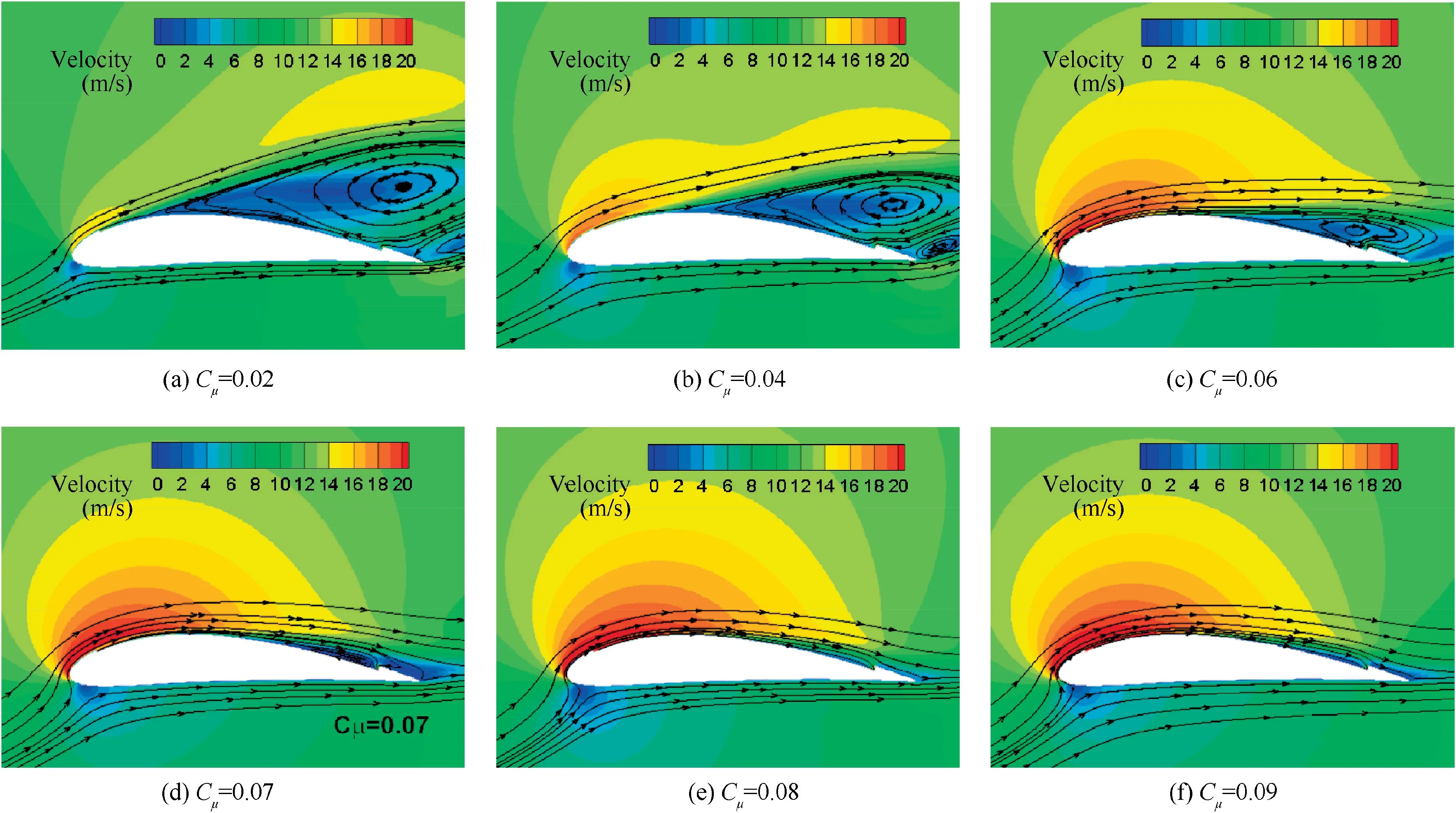
Fig. 20 Velocity contour and streamline under different momentum coefficients of CFJ airfoil (t=0.42 T).
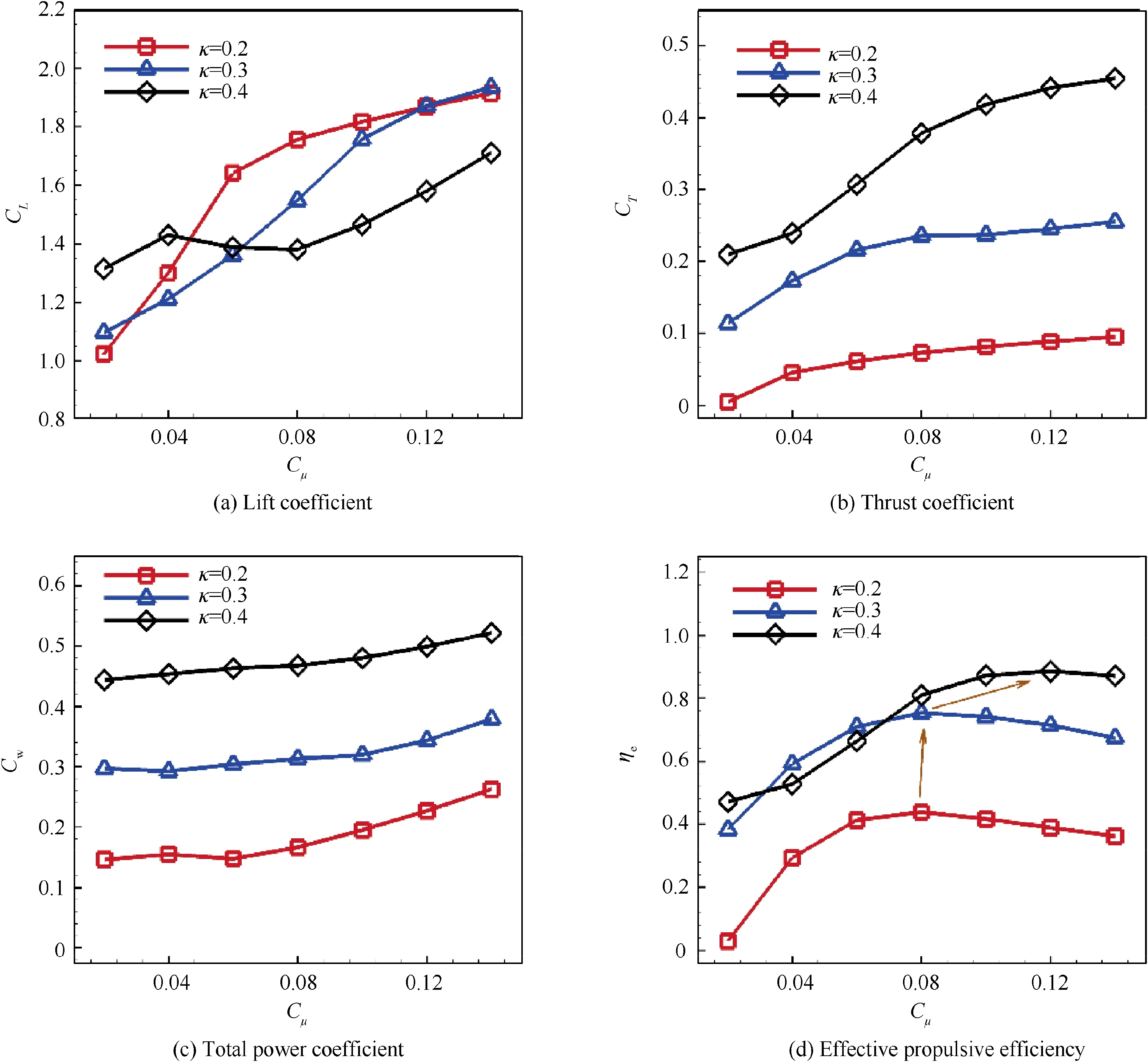
Fig. 21 Variation of time averaged lift coefficient, thrust coefficient, power coefficient and effective propulsive efficiency with different jet momentum coefficient for CFJ airfoil when κ=0.2, 0.3, 0.4.
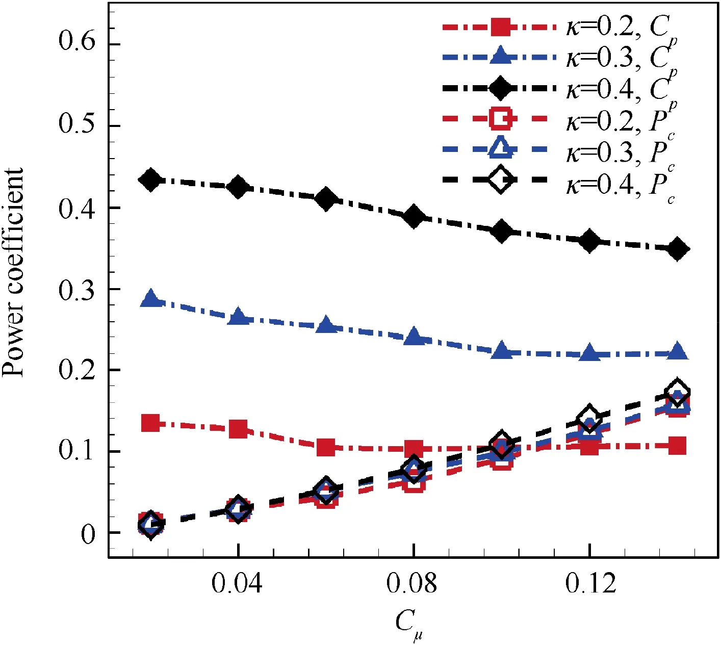
Fig. 22 Comparison of time averaged power coefficient at different κ levels.
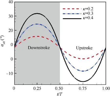
Fig. 23 Variation of effective angle of attack during a flapping cycle for κ=0.2, 0.3, 0.4.
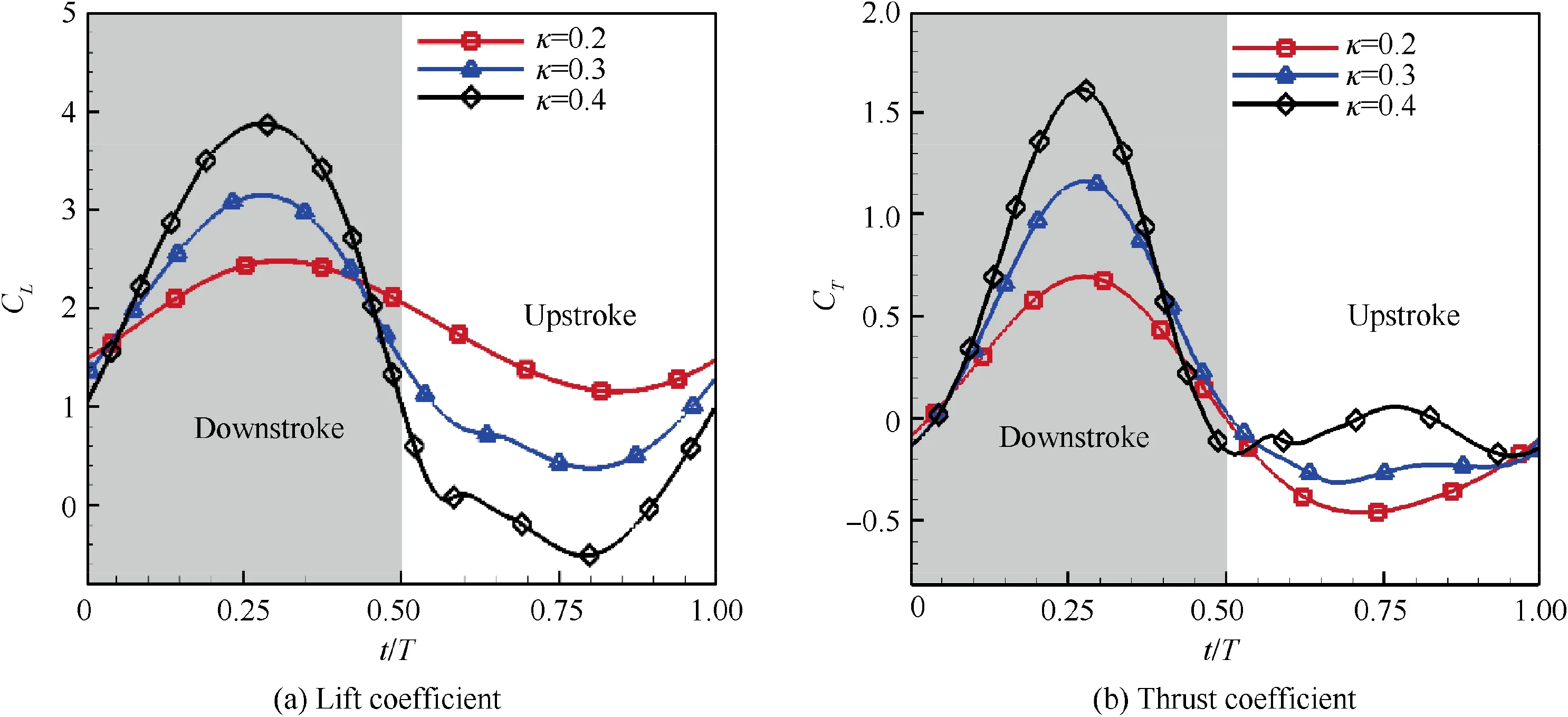
Fig. 24 Instantaneous lift coefficient and thrust coefficient of NACA6415-based CFJ airfoil during a flapping cycle for κ=0.2, 0.3, 0.4(Cμ=0.08).
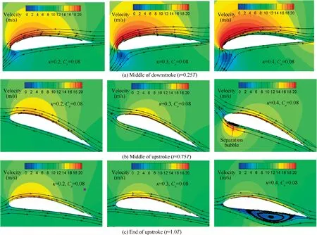
Fig. 25 Velocity contour and streamline of NACA6415-based CFJ airfoil during a flapping cycle for κ=0.2, 0.3, 0.4 (Cμ=0.08).
Velocity contour and streamline of NACA6415-based CFJ airfoil during a flapping cycle are depicted in Fig. 25. At middle of downstroke, a larger reduced frequency leads to the increase of effective angle of attack.Velocity of flow on upper surface becomes larger with κ increasing from 0.2 to 0.4,which leads to relatively lower pressure on upper surface of airfoil.Therefore, larger lift coefficient is acquired for airfoil with higher κ. Besides, large leading-edge suction also improves the thrust coefficient.At middle of upstroke,the effective angle of attack of CFJ airfoil becomes negative when κ is equal to 0.4. A small separation bubble appears near the leading edge of the lower surface of airfoil. The separation bubble travels downstream and grows in size from the middle of upstroke to the end of upstroke, which reduces lift coefficient of CFJ airfoil. As for thrust, the negative effective angle of attack is beneficial to the improvement of thrust characteristics for larger horizontal force projection is produced.
3.5.2. Effect of suction slot position and injection slot position
In this section, the influence of the positions of injection slot and suction slot on the aerodynamic performance of the CFJ airfoil is studied, with κ=0.2 and Cμ=0.04, 0.06, 0.08.
(1) Effect of suction slot position
Position of the suction slot is from 0.62 to 0.89 chord length. Simulation results of lift coefficient CL, thrust coefficient CT, effective propulsive efficiency ηeand total power coefficient Cware shown in Fig. 26. When Cμremains unchanged,the thrust coefficient decreases and the total power coefficient increases as the suction location moves backward.Therefore, the effective propulsive efficiency decreases as the suction location moves backward.
Velocity contour and streamline for CFJ airfoil at the end of downstroke under different suction locations when Cμ=0.04 and 0.06 are shown in Fig.27.The strength of flow separation vortex over the upper surface of the airfoil significantly increases when the suction position moves from 0.62c to 0.89c at Cμ=0.04. Therefore, it is suggested that if the position of suction slot is too close to airfoil trailing edge,the flow separation cannot be effectively suppressed under relatively small Cμ. Consequentially, both lift and thrust performance are reduced with suction position moving from 0.62c to 0.89c. When Cμrises to 0.06, flow separation is effectively suppressed by higher-energy jet.The backwards of the suction slot position only has small impact on the flow pattern. As a result, there is only small change in aerodynamic performance at relatively large Cμwhen the suction position changes.
(2) Effect of injection position
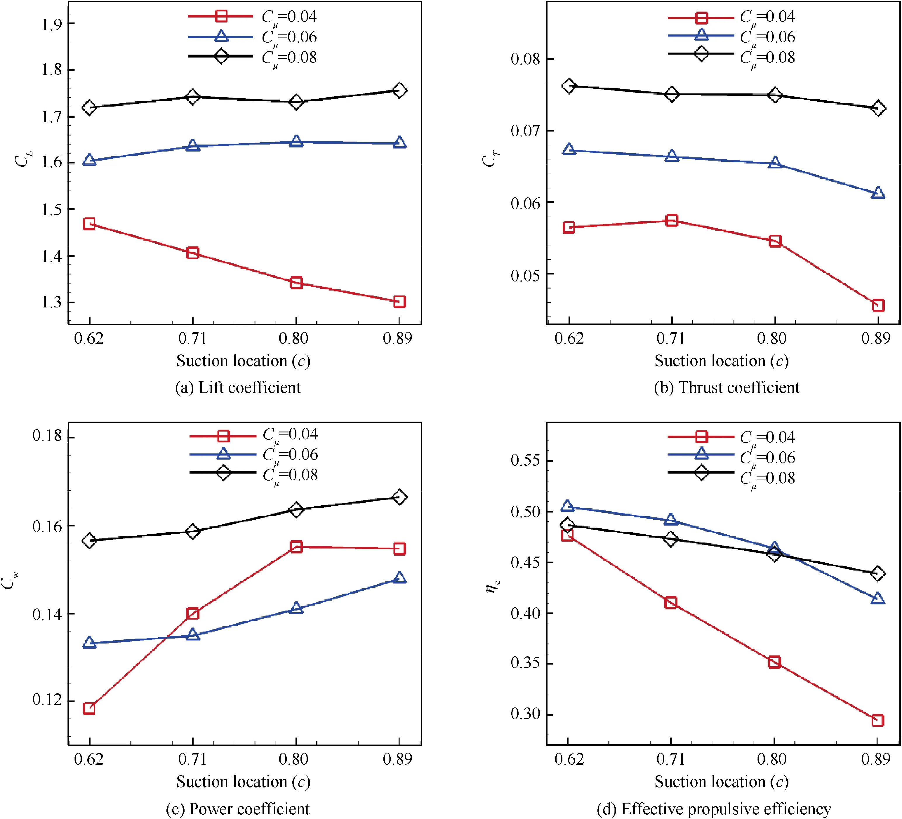
Fig. 26 Variation of time averaged lift coefficient, thrust coefficient, total power coefficient and effective propulsive efficiency with different suction locations for CFJ airfoil at Cμ=0.04, 0.06, 0.08.
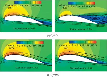
Fig. 27 Velocity contour and streamline for CFJ airfoil under different suction positions when Cμ=0.04 and 0.06 at end of downstroke.
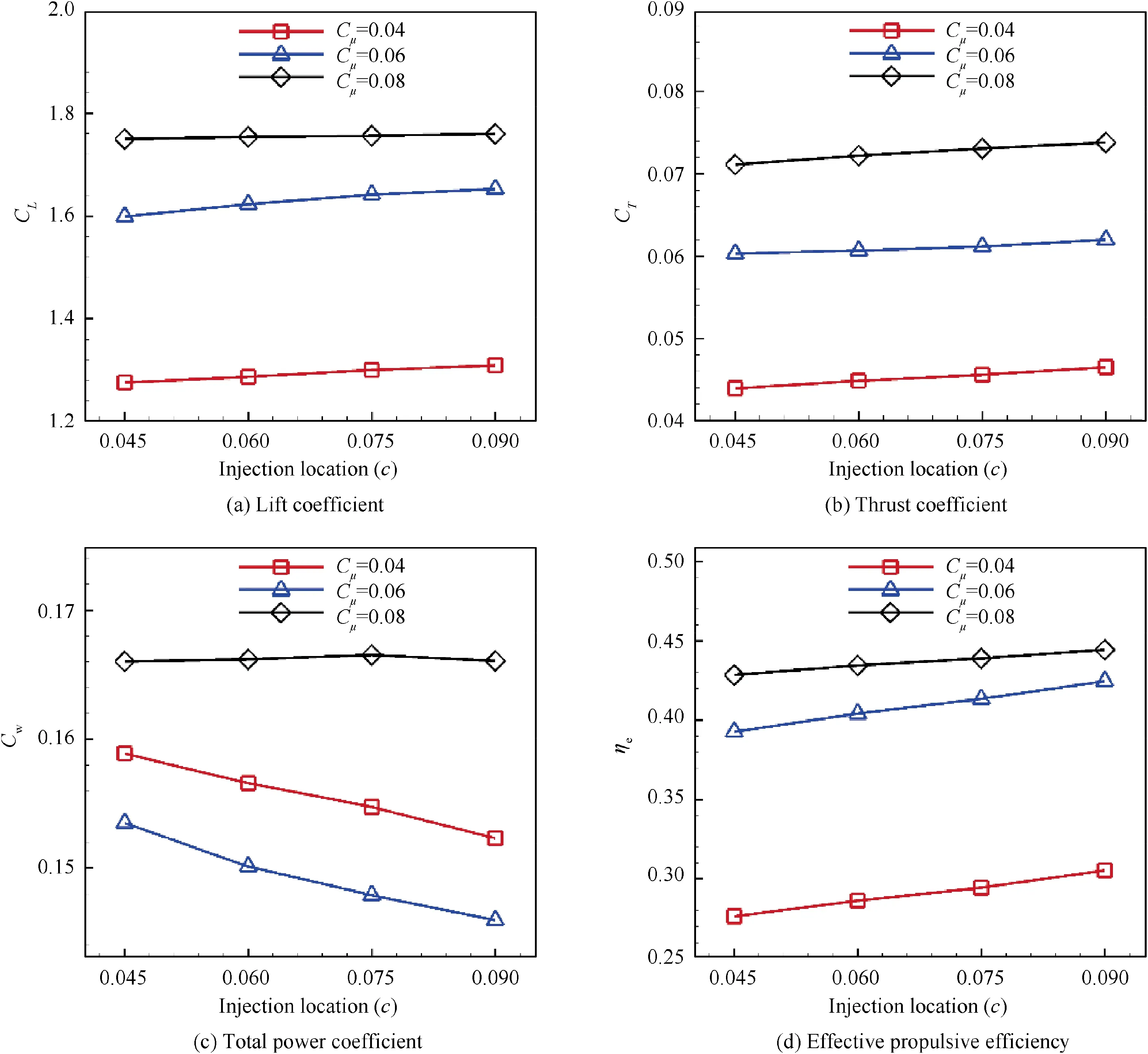
Fig. 28 Variation of time averaged lift coefficient, thrust coefficient, total power coefficient and effective propulsive efficiency with different injection locations for CFJ airfoil at Cμ=0.04, 0.06, 0.08.
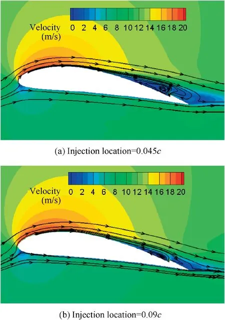
Fig. 29 Velocity contour and streamline for CFJ airfoil under different suction locations when Cμ=0.06 at end of downstroke.
The position of the injection slot is from 0.045 to 0.09 chord length.The simulation results of lift coefficient CL,thrust coefficient CT, total power coefficient Cwand effective propulsive efficiency ηeare shown in Fig. 28. When Cμ=0.04, 0.06 and 0.08, the thrust coefficient increases and the power coefficient generally decreases as the injection position moves backward.As a result, the effective propulsive efficiency shows a slight improvement as the injection location moves backward.
Velocity contour and streamline for CFJ airfoil under different suction locations when Cμ=0.06 at the end of downstroke are shown in Fig. 29. When the injection location moves from 0.045c to 0.09c of the airfoil, the main flow near the leading edge of the airfoil is accelerated over longer distances before mixing up with high-energy jet flow. Therefore,the range of high-velocity areas on the upper surface of the airfoil is increased, which leads to smaller flow separation over the suction surface of the airfoil. Lift coefficient, thrust coefficient, power coefficient and effective propulsive efficiency of CFJ airfoil are all benefited from improved flow patterns with injection slot location moving backwards.
3.5.3. Effect of variable Cμcontrol
Only constant Cμcontrol is considered for CFJ airfoil with flapping motion in Sections 3.4,3.5.1 and 3.5.2.In this section,a variable Cμjet control strategy based on quasi-steady aerodynamics is proposed to further improve effective propulsive efficiency. NACA6415-based CFJ airfoil with κ=0.2, injection slot located at 0.075c and suction slot located at 0.885c is adopted as a validation case in this part.
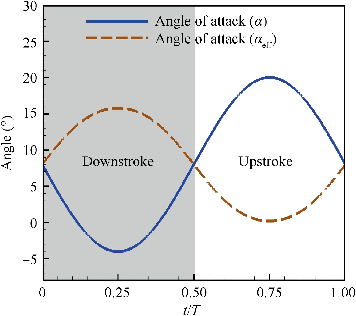
Fig. 30 Variation of effective angle of attack αeff and angle of attack α during a flapping cycle.
In Section 3.4.2, it has been pointed out that a law of variable jet momentum coefficient, which can exactly control the airfoil boundary layer flow without separation during flapping,will do better to maximize effective propulsive efficiency. In practice, it is very difficult to design a law of Cμwhich can exactly control the flow separation in unsteady flow.However,according to quasi-steady aerodynamics, separation on flapping airfoil is highly related to the time courses of αeff. Based on this,a variable-Cμjet control strategy is proposed.The process is as follows.
Firstly, effective angle of attack αeffis computed based on airfoil flapping motion. The time course of αefffor NACA6415-based CFJ airfoil at κ=0.2 is shown in Fig. 30.It can be seen that αeffvaries from 0° to 16° during the entire flapping period.
Secondly, the least Cμrequired to keep flow fully attached over the upper surface of airfoil at different αeffis investigated.For each value of αeff,steady numerical simulations are carried out at a series of Cμ.Whether the flow separates or not for all cases are recorded, as shown in Table 5.
Thirdly, the relationship between the least Cμrequired to keep flow fully attached and the corresponding αeffis obtained through regression analysis. For NACA6415-based CFJ airfoil, the expression is shown as

Finally,the law of variable Cμcontrol in Eq.(13)is adopted for the NACA6415-based CFJ airfoil simulation. Aerodynamic characteristics are compared with those using constant Cμcontrol at the same flow condition. The time averaged Cμfor variable Cμcontrol is 0.05. As shown in Fig. 31, the aerodynamic performance of CFJ with variable Cμcontrol is superior in all respects, compared with the constant Cμcontrol at Cμ=0.05. The effective propulsive efficiency of CFJ airfoil with variable Cμis 0.538, which is even 22.6% higher than the optimal value of constant Cμsimulation.It is demonstrated that a variable Cμcontrol does perform better for effective propulsive efficiency improvement of CFJ airfoil.

Table 5 Flow pattern on the upper surface of airfoil under different αeff and Cμ.
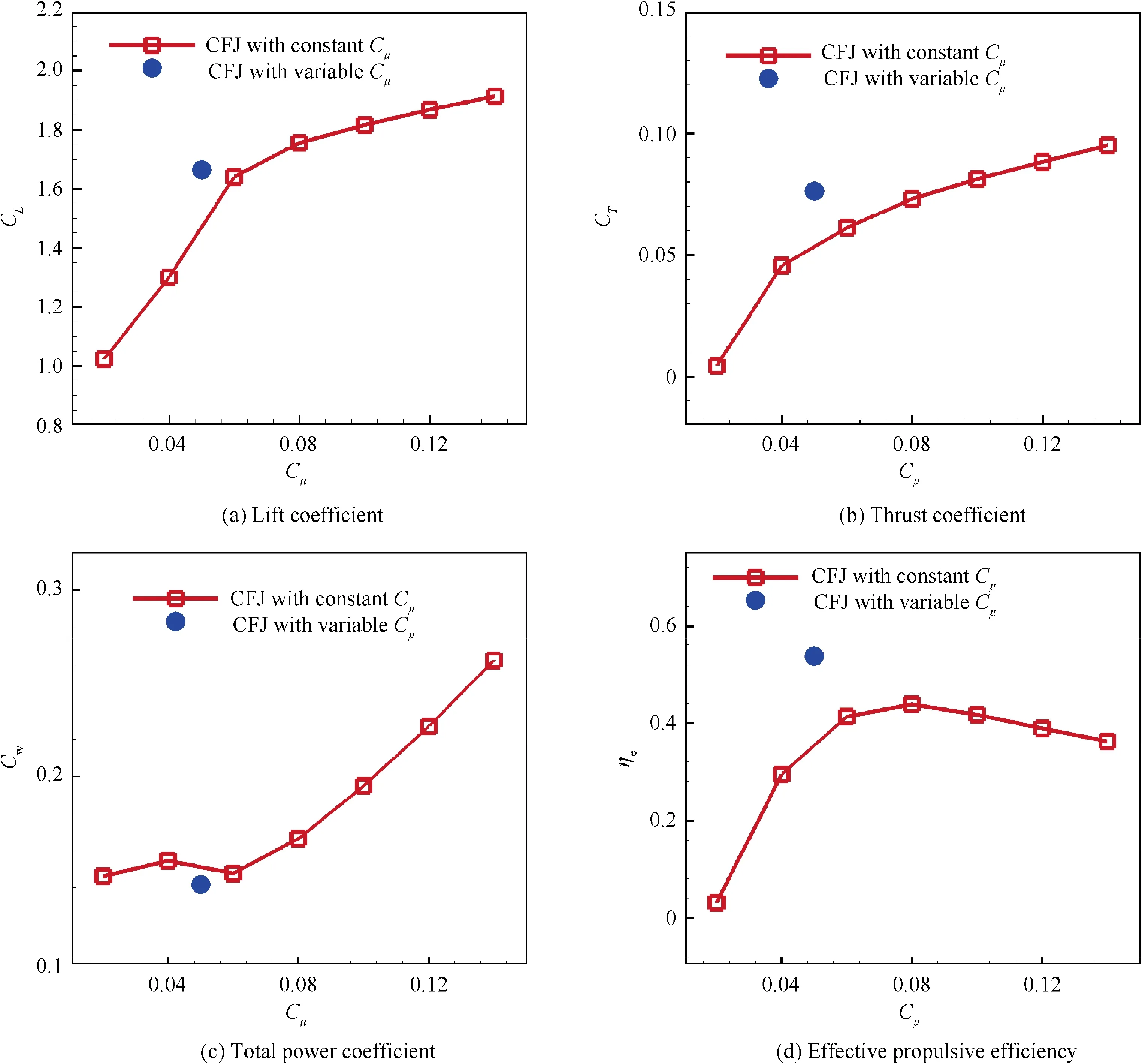
Fig.31 Comparison of time averaged aerodynamic coefficient under constant Cμ control and variable Cμ control for NACA6415-based CFJ airfoil at κ=0.2.
4. Conclusions
Co-flow jet concept is applied to flapping airfoil at low Reynolds number for the first time, and the effect of CFJ on aerodynamic performance and effective propulsive efficiency of flapping airfoil is systematically investigated by unsteady Reynolds-averaged Navier-Stokes simulations. The conclusions obtained are as follows:
(1) When the co-flow jet is inactive, the jet channel has a negative effect on flapping airfoil aerodynamic performance.Periodic-averaged lift,thrust and propulsive efficiency of jet-off airfoil are all smaller than those of baseline airfoil.
(2) When the co-flow jet is active,the lift and thrust characteristics for flapping airfoil can be significantly promoted with Cμgrowing. Relatively smaller flow separation at trailing edge and stronger suction at leading edge are achieved during most of the flapping cycle when Cμgoes higher, which hugely dedicates to enhancement of aerodynamic force for flapping airfoil. Besides, effective propulsive efficiency of flapping airfoil can be improved with CFJ active flow control. A tradeoff between thrust improvement and power consumption will dominate the variation of effective propulsive efficiency with Cμgrowing.
(3) Reduced frequency has significant influence on the aerodynamic performance of the CFJ airfoil. The optimal effective propulsive efficiency for NACA6415-based CFJ airfoil is 0.884 at κ=0.4, which is 101.4% higher than that at κ=0.2,showing great potential for aerodynamic efficiency improvement with relatively larger κ.
(4) To achieve higher thrust coefficient and effective propulsive efficiency, position of suction slot and injection slot for flapping airfoil should be carefully designed to reduce flow separation for flapping airfoil.
(5) Variable Cμcontrol performs better for effective propulsive efficiency improvement of CFJ airfoil. Compared with using constant Cμ, an increase of effective propulsive efficiency by 22.6%has been achieved by using variable Cμfor NACA6415-based CFJ airfoil at κ=0.2.
Numerical results of the present study show powerful ability for CFJ to improve aerodynamic performance of flapping airfoil under considerable power consumption. Further investigations will focus on CFJ effect on aerodynamic performance of three-dimensional flapping wing. Besides, closed-loop control to achieve an optimization control effect for flapping airfoil will also be studied.
Acknowledgements
This study was co-supported by the National Key Research and Development Program of China (No.:2017YFB1300102) and the National Natural Science Foundation of China (No.: 11872314).
 CHINESE JOURNAL OF AERONAUTICS2020年10期
- CHINESE JOURNAL OF AERONAUTICS的其它文章
- A novel surrogate modeling strategy of the mechanical properties of 3D braided composites
- A user-friendly yield criterion for metals exhibiting tension-compression asymmetry
- Aerodynamic characteristics of morphing wing with flexible leading-edge
- High cycle fatigue failure with radial cracks in gears of aero-engines
- Motion equations of hemispherical resonator and analysis of frequency split caused by slight mass non-uniformity
- Light weight optimization of stratospheric airship envelope based on reliability analysis
