基于航迹-航深信息的声学测速基阵校准技术研究
袁书明,曹忠义
基于航迹-航深信息的声学测速基阵校准技术研究
袁书明1,曹忠义2,3
(1. 海军装备研究院,北京 100073;2. 哈尔滨工程大学水声技术重点实验室,黑龙江哈尔滨 150001;3. 哈尔滨工程大学水声工程学院,黑龙江哈尔滨 150001)
针对声学多普勒测速仪安装过程中存在的基阵坐标系与载体坐标系之间的不重合问题,以实际工程应用为背景,提出了综合采用测速仪的速度推算航迹及其波束域斜距信息的三维安装偏角精确校准方法。利用航偏角校准精度受纵、横摇偏角影响小的特点,采用载体上的高精度全球定位系统(Global Positioning System, GPS)、姿态装置推算航迹建立航偏角观测方程,实现航偏角校准。在此基础上,利用波束域斜距与纵、横摇偏角之间的几何方程,精确解算纵、横摇偏角。仿真分析了校准算法性能,并通过外场试验数据验证了校准算法的有效性。结果均表明该方法能够实现基阵三维安装偏角的精确校准,有效提高了导航精度,具有较好的工程应用价值。
声学多普勒测速仪;安装误差校准;最小二乘估计;联合校准
0 引言
声学多普勒测速仪是利用多普勒效应,通过估计弱散射回波信号的多普勒频移信息实现对底绝对/对水相对速度的信息解算。与传统电磁式、水压式计程仪相比,具有测速精度高、抗污染能力强、使用稳定可靠等特点,是现代声学导航[1-4]、水文观测[5-7]等的重要组成部分。声学多普勒测速仪输出的速度按照参考坐标系的不同,分为仪器坐标系、载体坐标系和大地坐标系三种,分别是基于基阵轴线、载体艏艉线和东-北-天为参考坐标系,各坐标系下的速度信息可通过坐标旋转矩阵转换,以满足不同的导航功能需求:载体坐标系与大地坐标系之间可利用航姿信息,通过坐标旋转变换操作实现两个坐标系速度的相互转换;仪器坐标系与载体坐标系之间的旋转变换操作,依赖于基阵与载体之间的安装偏角,它是一组确定常量,需要通过精确校准获取,其校准精度直接影响水下导航系统的性能。
传统水下声呐定标、平均速度等校准方法受环境条件的影响严重,对载体的航速、航向和航程等均有严格限定,且主要解决的是一维航偏角校准问题,其校准精度和校准效率仍不理想[8-11]。为此,文献[12]提出了一种基于最小二乘的改进校准方法,实现了任意航迹、航速下的安装误差校准,但受GPS的高程信息起伏较大、水面校准时的测速仪垂向速度较小的因素影响,该方法主要用于一维航偏角的精确校准,在纵横摇偏角小于3°时仍能获得优于0.05°的校准精度。文献[13]提出采用航速-航深校准方法,在航偏角估值基础上,利用线性方程获取纵横摇偏角,但该方法的航偏角校准精度较低,会直接影响纵横摇偏的校准结果,无法满足大机动平台高精度水声导航系统的使用需求。为此,本文以实际工程应用为背景,综合文献[12]和[13]校准方法,提出采用基于航迹-航深相结合的校准方法,借助于高精度GPS和姿态装置,实现三维安装偏角的精确校准,仿真和湖上试验结果验证了该方法的有效性。
1 校准方法
1.1 航偏角校准

通常测速仪输出的是自身仪器坐标系下的速度,它与大地坐标系速度矢量之间满足:


1.2 纵横摇偏角校准

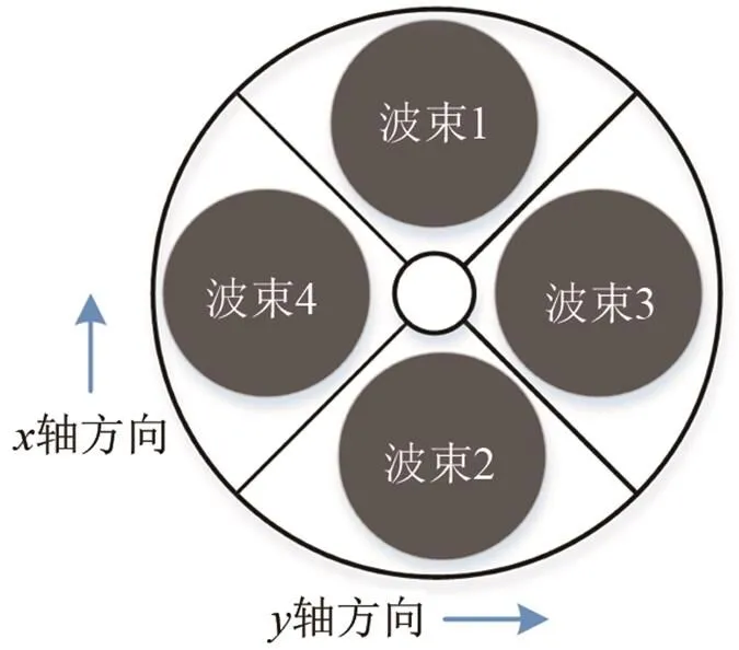
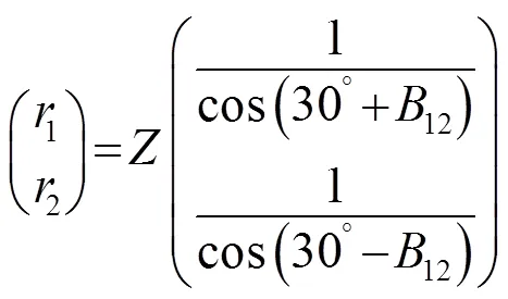
利用三角形几何关系式可知[13]:


2 仿真结果与分析
由上述分析可知,校准精度与观测设备测量精度密切相关,直接对式(8)~(11)进行误差分析无法得到解析结果,在此采用蒙特卡洛方法仿真分析校准方法的性能,仿真条件如下:
(1) 设载体保持直线匀速航行,水平方向速度为5 m/s,垂直方向速度以周期为20 s、振幅为0.05 m/s的正弦规律起伏,水深为50 m;
(4) 测速仪的斜距测量精度为0.2 m。


(a)
(b)
(c)


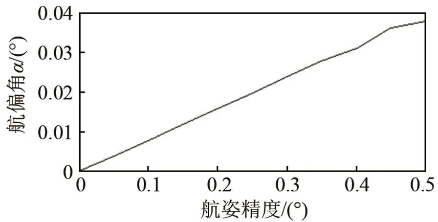
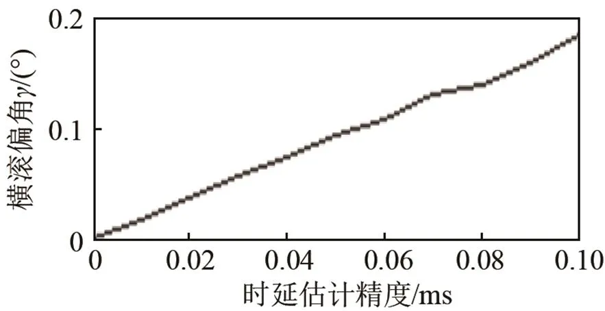
图3 姿态精度对校准性能的影响

(a)
(b)

(c)
3 外场试验验证
3.1 试验场景及设备安装


图5 系统安装示意图
3.2 试验结果与分析
依据上述校准方法获得的三维安装偏角校准结果如表1所示。为验证安装误差校准的实际效果,规划了矩形和圆形2种测线,比对校准前后测速仪推算航迹与GPS航迹间的重合度,验证安装误差校准的实际效果。矩形测线期间,试验船在每个矩形边上以固定航向角航行,进行了2组闭合试验,航程约9.1 km;圆形测线时试验船以最大舵角旋转航行,航程约0.75 km。
图6(a)和图6(b)为2种测线下的三维航迹对比曲线,其中粉色线为校准前速度仪航迹线,红色线为校准后速度仪航迹线,黑色线为GPS实际航线。

表1 三维安装偏角校准结果

(a) 矩形测线
(b) 圆形测线
图6 三维航迹线
Fig.6 Three-dimensional tracks
图7和图8分别为校准前、后水平和垂直方向航迹对比曲线。从图中可以看出:安装误差的影响随时间累积增大,未经校准补偿的航迹线渐渐偏离实际航线;安装误差校准是有必要的,校准后能够明显改善测速仪的输出数据质量,验证了校准方法的有效性。
表2给出了2种测线终点位置处的导航坐标结果,其中矩形测线校准前、后导航精度为分别为5.30%、0.13%,圆形测线校准前、后导航精度为分别为16.50%、0.19%,可以明显看出,安装偏角误差经过校准补偿带来的性能改善,进一步证明了该校准算法的有效性。

表2 两种测线校准结果
注:E/m,N/m,U/m分别表示东向、北向和天向坐标值,单位为m。
对比2种测线也可以看出在航行过程期间,校准后的矩形测线与实际测线间的实时测线误差比率要优于圆形测线,作者认为可能是GPS天线与声学基阵之间的位置测量误差造成的,若将位置偏差也作为估计参量可能会改善校准精度,但会增加校准难度,这有待做进一步分析。

(a) 矩形测线
(b) 圆形测线
图7 水平方向航迹线
Fig.7 Horizontal tracks

(a) 矩形测线
(b) 圆形测线
图8 垂直方向航迹线
Fig. 8 Vertical tracks
4 结论
精确的安装偏角校准工作是提高多普勒速度仪应用性能的一个重要环节。本文综合利用速度仪的航迹-航深信息获取声学基阵的三维安装偏角,可操作性和校准精度易于保证。湖上9.1 km航程的矩形准闭环测线和0.75 km航程的圆形准闭环测线实验结果表明:校准后的速度仪航迹推算精度均控制在了0.2%以内,验证了该方法的有效性。该方法适用于各种声学多普勒速度仪与载体之间的安装角度估计,具有一定的工程应用价值。
[1] Navigator ADCP/DVL User’s Guide [EB/OL]. RD Inc. http://support. rdinstruments. com/documentation/cc_documents. aspx.
[2] Snyder J. Doppler Velocity Log (DVL) navigation for observation-class ROVs[C]//OCEANS, IEEE, 2010: 1-9.
[3] DOISY Y. Theoretical accuracy of Doppler navigation sonars and acoustic Doppler current profilers[J]. IEEE, 2004, 29(2): 430-441.
[4] CAO Zhongyi, ZHANG Dianlun. A method for testing phased array acoustic Doppler velocity log on land[J]. Applied Acoustics. 2016, 103: 102-109.
[5] Rennie C D, Rainville F. A case study of precision of GPS differential correction strategies: influence on ADCP velocity and discharge estimates[J]. Journal of Hydraulic Engineering, 2006, 132(3): 225-34.
[6] Wagner C R, Mueller D S. Comparison of bottom-track to global positioning system referenced discharges measured using an acoustic Doppler current profiler[J]. Journal of Hydraulic Engineering, 2011, 401: 250–8.
[7] Mueller D S, Wagner C R. Measuring discharge with acoustic Doppler current profilers from a moving vessel[J]. US Geol Surv Tech Methods, 2009, 3A: 22:72.
[8] Pollard R, Read J. A method for calibration shipmounted acoustic Doppler profiler and the limitation of gyro compasses[J]. Journal of Atmospheric and Oceanic Technology, 1989, 6(6): 859-865.
[9] ZHAO Jianhu, CHEN Zhigao, ZHANG Hongmei. A robust method for determining the heading misalignment angle of GPS compass in ADCP measurement[J]. Flow Measurement and Instrumentation, 2014, 35(3): 1-10.
[10] Terrence M. On in situ calibration of shipboard ADCPs[J]. Atmospheric and Oceanic Technology, 1989, 29(2): 169-172.
[11] James LH, Johanna HR. Analysis of bottom-track and compass error in a self-contained acoustic Doppler diver navigation console. Journal of Atmosphere Oceanic Technology[J]. 2010, 27(7): 1229- 1238.
[12] 曹忠义, 郑翠娥, 张殿伦. 声学多普勒速度仪安装误差校准方法[J]. 哈尔滨工程大学学报, 2013, 34(4): 434-439. CAO Zhongyi, ZHENG Cuie, ZHANG Dianlun. A study on the calibration of installation error in acoustic transducer[J]. Journal of Harbin Engineering University, 2013, 34(4): 434-439.
[13] Clifford L. Trump. Calculation of ADCP alignment offsets using single-beam velocity and depth data[J]. Journal of Atmospheric and Oceanic Technology, 1997(14): 1252-1255.
[14] GRAHAM A. Kronecker products and matrix calculus with applications[M]. New York: Wiley, 1981: 21-36.
Study on the calibration of acoustic Doppler velocity transducer based on the dead reckoning and depth
YUAN Shu-ming1, CAO Zhong-yi2,3
(1. Navy Academy of Armament, Beijing 100073, China;2. Acoustic Science and Technology Laboratory, Harbin Engineering University, Harbin 150001,Heilongjiang,China;3. College of Underwater Acoustic Engineering, Harbin Engineering University, Harbin 150001,Heilongjiang,China)
How to accurately estimate the installation angles between the carrier and the acoustic array is one of the main factors that affect the data quality of acoustic Doppler velocity meter in the application. A joint calibration method based on the trajectory between GPS and velocity meter, the depth of velocity meter is applied to estimate the three-dimensional installation angles. Firstly, based on the characteristic that misalignment pitchand rollshow little impact on misalignment heading, observation equation ofis set up with the use of high-precision GPS and attitude device on carrier, and dead reckoning. And thenis calibrated. Secondly, taking use of the geometric equation between the distance in beam space andor, the exact solution can be obtained. In order to evaluate the performance of the method, the effect caused by the observation equipment is simulated. And field experiment is made to verify its effectiveness. It shows that the method effectively solves the problem of the array installation angles, which can be applied in engineering.
acoustic Doppler velocity meter; calibration of installation error; Least Squares Method; joint calibration method
TB556
A
1000-3630(2017)-05-0431-06
10.16300/j.cnki.1000-3630.2017.05.006
2016-12-16;
2017-03-11
袁书明(1965-), 男, 安徽砀山人, 博士, 高级工程师, 研究方向为船舶导航论证和技术。
曹忠义, E-mail: caozhongyi@hrbeu.edu.cn

