两位置法快速测定近钻头惯性测量模块的温漂模型
刘云峰,方文斌,董景新
(清华大学 精密仪器系 高精度惯性仪表及系统技术教育部重点实验室,北京 100084)
两位置法快速测定近钻头惯性测量模块的温漂模型
刘云峰,方文斌,董景新
(清华大学 精密仪器系 高精度惯性仪表及系统技术教育部重点实验室,北京 100084)
近钻头惯性测量模块(Near-bit Inertial Measurement,NIM)用于石油钻井中实时测量导向外套的姿态角,是导向钻进闭环控制中的重要组成部分。它采用三轴加速度计组合测量重力加速度实现姿态角测量。为了提高加速度计在工作温度范围内的测量精度,需对其进行温漂模型标定。针对三轴加速度计组合的传统 12位置翻滚温度模型测定方法存在耗时长、操作效率低的局限性,提出一种新的加速度计三轴组合温度模型标定方法——两位置法,并通过实验验证了温度补偿的效果。在10℃~150℃的温度范围内,补偿后加速度的测量精度达5×10⁻⁴g,完全满足NIM测量姿态角的要求。
随钻测量;加速度计;零偏;标度因数;温度补偿
近钻头惯性测量模块(NIM)用于在石油领域的旋转导向钻井过程中,对旋转导向外套的重力工具面角、井斜角进行实时测量,并反馈给导向外套上的液压推力控制系统,实现导向钻进的闭环控制[1]。
NIM 由三只石英挠性加速度计和数据采集处理电路板组成,加速度计呈三轴正交状态安装,可以实时测量重力加速度在三个轴向上的分量,从而解算出NIM模块的俯仰角(即井斜角)和横滚角(即重力工具面角)。该模块井下实际工作温度条件为 10℃~150℃,由于石英挠性加速度计和数据处理电路的输出特性均受环境温度变化的影响,进而影响NIM模块对井斜角和重力工具面角测量的精度,因此需要对NIM模块进行温度模型测定并加以补偿。
对于三轴捷联安装的加速度计组合,传统的温度模型测定方法是12位置翻滚法,即是将被测三轴加速度计组合安装于正六面体或三轴位置转台,通过在重力场中进行 12位置翻滚,记录各轴加速度计输出数据,可以解算出各轴加速度计在当前温度下的零偏及标度因数。改变环境温度,在不同温度条件下采用12位置翻滚法测定各轴加速度计的零偏及标度因数,就可以获得各轴加速度计零偏及标度因数的温度模型[2-9]。
此测定方法在工程应用中的局限性在于时间长,操作效率低,或是需要专用的大型设备(带温控的三轴转台),且无法满足对多套加速度计组合同时进行温漂模型标定的需求。因此,需要探索一种适用于近钻头惯性测量模块的温度模型快捷标定方法。
本文在对加速度计的温度特性进行分析建模的基础上,设计了专用于该实验的标定工装,提出静止无翻滚的两位置法进行温度补偿实验,估算出温度模型参数,并利用该结果对系统进行了温度补偿验证实验。实验结果证明,加入该温度补偿模型后能有效提高加速度计在全温范围内的测量精度,体现了两位置法的可行性和高效率。
1 硬件介绍
NIM的三只加速度计本身自带温度输出。加速度计的三个输出电压和三个温度输出一同经过调理电路输入到单片机的AD转换模块,数据在单片机中计算后以0.25 Hz的速度经串口上传至计算机并存储。NIM组成框图如图1所示。
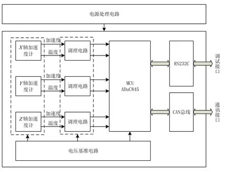
图1 NIM组成框图Fig.1 Block diagram of near-bit inertial measurement
2 两位置法
2.1 两位置法理论推导
NIM 系统采用的石英挠性加速度计的测量输出电压(经采样电阻后)与输入加速度呈线性关系,其非线性误差小于200×10-6[10],因此其输入输出关系可用如下公式描述:

式中:V为加速度计输出电压(mV);a为输入加速度(g);K0为零偏(mV);K1为标度因数(mV/g)。
在任意温度t下,加速度计输出V(t)满足如下公式:

式中:K0(t)是加速度计零偏关于温度的函数;K1(t)加速度计标度因数关于温度的函数。
两位置法的关键是,在位置1时,加速度计的输入加速度为a0,在位置2时,加速度计的输入加速度为-a0。那么,两个位置的加速度计输出有如下关系:

由式(3)(4)解算得:
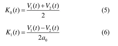


同理,对标度因数―温度曲线K1(t)-t进行多项式拟合,得到:


再对拟合得到的温度模型系数常数项进行微调。根据加速度计的静态常温标定数据,已知在室温t0下,加速度计的零偏和标度因数,对式(7)(8)中的常数项系数进行调整后可得式(9)~(11),其中为零偏温度模型系数常数项,为标度因数温度模型系数常数项,式(11)表示加速度计温度模型方程。

2.2 两位置法标定NIM模块的温漂模型

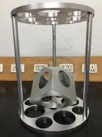
图2 标定工装图Fig.2 Calibration equipment picture
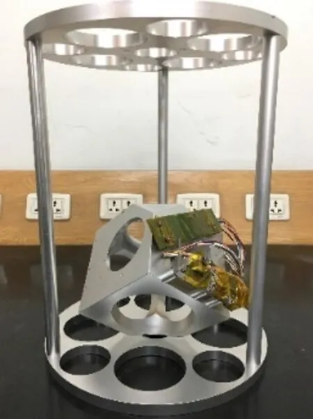
图3 (a) 位置1安装图Fig.3(a) Construction picture of position I
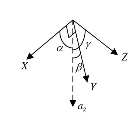
图3 (b) 位置1加速度计敏感轴方向示意图Fig.3(b) Rotation of accelerometers at position I

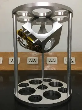
图4 (a) 位置2安装图Fig.4(a) Construction picture of position II
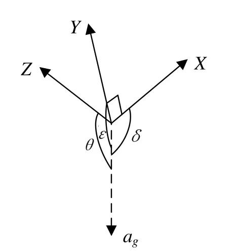
图4 (b) 位置2加速度计敏感轴方向示意图Fig.4(b) Rotation of accelerometers at position II


以X轴加速度计为例,根据式(5)(6),解算X轴加速度计的零偏和标度因数可得:
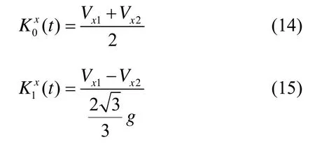
式中:Vx1为X轴加速度计在位置1时的输出;Vx2为X轴加速度计在位置2时的输出;(t)为X轴加速度计的零偏;(t)为X轴加速度计的标度因数。
改变温度t,即可得到X轴加速度计的标度因数-温度曲线(t)-t和零偏-温度曲线(t)-t。采用多项式拟合并根据静态常温条件下精确标定的零偏及标度因数进行微调后,即得到X轴加速度计温度模型方程。同理可得Y轴、Z轴的加速度计温度模型方程。
3 实验验证与分析
3.1 实验步骤
实验总体分为三部分:第一部分是两位置法测定温度模型;第二部分是12位置法测定温度模型;第三部分是静态验证实验,对两种方法的温度补偿效果进行对比判断。以下为具体实验步骤:
① 首先将NIM安装于温度标定工装上,再置放于温控箱中水平平台上,使三轴加速度计处于位置 1状态。启动温控箱,设定升温曲线自10℃~150℃匀速升温。记录并保存位置1升温段数据。
② 重新开始记录位置1降温端数据,设定温控箱自10℃~150℃共8个温度点进行逐级降温的恒温控制,降温速率不限。保存位置1降温段数据。
③ 将标定工装倒过来,使三轴加速度计处于位置2状态。升温过程同第①步,实验结束后,记录并保存位置2升温段数据。
④ 对NIM进行12位置翻滚实验。设定温控箱自10℃~150℃均匀分布10个温度点进行逐级升温的恒温控制,在每个温度点进行12位置翻滚,记录并保存实验数据。
⑤ 把NIM从标定工装上拆下,以任一倾斜姿态(不同于两位置法中的姿态,且保证三轴加速度计均有一定的加速度输入量)固定NIM于温控箱内进行静态升温验证实验,记录并保存实验数据。
3.2 实验结果分析
利用位置 1降温段数据解算三只加速度计测温传感器的模型系数。根据8个温度点的各轴加速度计测温传感器的输出,做出各轴加速度计测温传感器输出数字量-温控箱设定温度曲线,用线性拟合得到各轴加速度计测温传感器的输出-温度模型,如表 1所示。此模型可用于NIM系统测量各轴加速度计部位的真实环境温度。

表1 三轴加速度计测温传感器模型系数Tab.1 Model coefficients of three-accelerometer temperatur e sensors
利用位置1、位置2的升温段数据获取三只加速度计的输出-温度模型。以X轴加速度计为例,以温度为横坐标,分别做出位置1、位置2加速度计输出数字量的散点图,如图5所示,并分别用最小二乘拟合得到X轴加速度计输出-温度的二次函数模型,如表2所示。

表2 X轴加速度计输出-温度模型系数Tab.2 Output-temperature model coefficients ofX-axis accelerometer
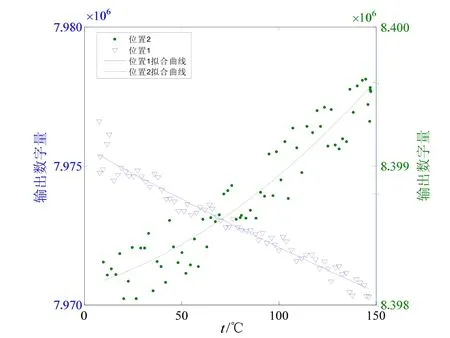
图5 X轴加速度计于两位置的输出Fig.5 Outputs ofX-axis accelerometer at the two positions
以位置1升温段数据记录的温度为横坐标,根据表 2中位置 2的输出-温度拟合结果,求得与位置1相同温度下在位置2时的X轴加速度计输出数字量。根据式(14)(15)求出各个温度点对应的零偏和标度因数并分别做出散点图,如图6(a)和图6(b)所示。对两个散点图进行二次拟合,即可得到X轴加速度计的标度因数-零偏曲线和零偏-温度曲线。
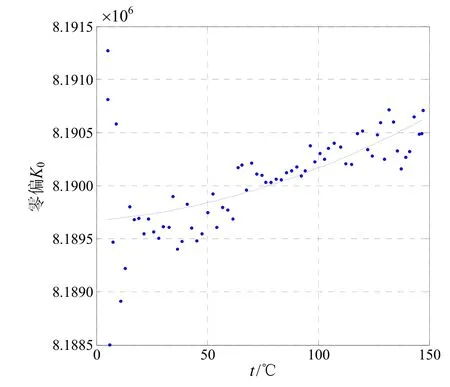
图6 (a) X轴加速度计的零偏-温度曲线Fig.6(a) Bias vs. temperature forX-axis accelerometer
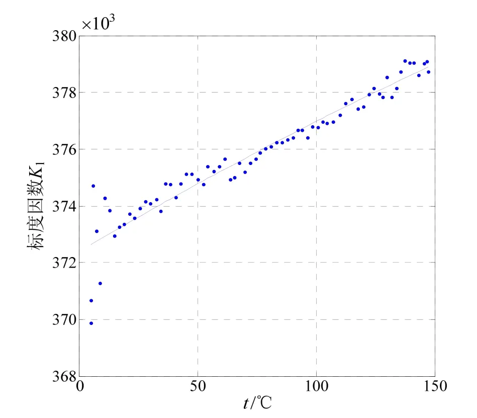
图6 (b) X轴加速度计的标度因数-温度曲线Fig.6(b) Scale-factor vs. temperature forX-axis accelerometer
最后根据静态常温(25℃)下标定所得的标度因数和零偏对温度模型系数常数项进行微调,得到X轴加速度计的温度模型参数。用以上方法计算Y轴、Z轴加速度计的温度模型参数,最终结果如表3所示。在12位置翻滚实验中得到各轴加速度计在10个温度点下的标度因数和零偏,拟合出标度因数-温度曲线和零偏-温度曲线,最终得到12位置翻滚法下的三轴加速度计温度模型。

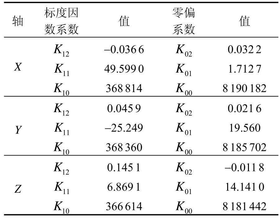
表3 两位置法所得三轴加速度计温度模型系数Tab.3 Temperature model coefficients of three accelerometers from the new method
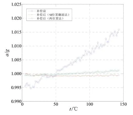
图7 总重力曲线对比Fig.7 Comparison on gravity curves
4 结 论

(References):
[1] Gorgone I, Gomez J, Uddenberg G. Remote intelligence: The future of drilling is here[C]//SPE 112231. Amsterdam, the Netherlands: Society of Petroleum Engineers, 2008.
[2] 孙宵, 董景新, 顾启泰. 近钻头测斜器温度建模与补偿[J]. 清华大学学报(自然科学版), 2013, 53(9): 1343-1346. Sun Xiao, Dong Jing-xin, Gu Qi-tai. Temperature modeling and compensation of At-bit inclinometer[J]. Journal of Tsinghua Univ (Sci & Technol), 2013, 53(9): 1343- 1346.
[3] Wu Shengnan, Yan Guofeng, Zhenggang Lian, et al. An open-cavity Fabry-Perot interferometer with PVA coating for simultaneous measurement of relative humidity and temperature[J]. Sensors and Actuators B: Chemical, 2015, 225: 50-56.
[4] Lee Jungshin, Rhim J. Temperature compensation method for the resonant frequency of a differential vibrating accelerometer using electrostatic stiffness control[J]. Journal of Micromechanics and Microengineering, 2012, 22(9) : 95016-95026.
[5] Mackley J, Nahavandi S. Active temperature compensation for an accelerometer based angle measure device[C]// Proceeding of World Automation Congress. Piscataway, USA, 2004: 383-388.
[6] Zhou A, Qin B, Zhang Y, et al. Hybrid structured fiberoptic Fabry-Perot interferometer for simultaneous measurement of strain and temperature[J]. Optics Letters, 2014, 39(18): 5267.
[7] Jia PG, Wang DH, Yuanl G, et al. An active temperature compensated fiber-optic fabry-perot accelerometer system for simultaneous measurement of vibration and temperature[J]. IEEE Sensors Journal, 2013, 13(6): 2334-2340.
[8] Yulianti I, Supa’at A S M, Idrus S M, et al. Design of fiber Bragg grating-based Fabry-Perot sensor for simultaneous measurement of humidity and temperature[J]. Optik -International Journal for Light and Electron Optics, 2013, 124(19): 3919-3923.
[9] 柳小军, 杨波, 袁安富, 等. 基于集成温度传感器的硅微陀螺仪数字化温度补偿研究[J]. 传感技术学报, 2014, 27(6): 770-774. Liu Xiaojun, Yang Bo, Yuan An-fu, et al. Research on digital temperature compensation of silicon micro gyroscope based on integrated temperature sensor[J]. Chinese Journal of Sensors and Actuators, 2014, 27(6): 770-774.
[10] Chen Fubin, Zhang Kebei. Identification for temperature model and the method for temperature compensation of quartz flexible accelerometer[C]//IEEE Advanced Information Technology, Electronic & Automation Control Conference. Chongqing, China: 2015: 841-845.
[11] 孙 霄, 董景新, 顾启泰. 近钻头测斜器最优八位置标定法[J]. 中国惯性技术学报, 2014, 22(1): 5-8. Sun Xiao, Dong Jing-xin, Gu Qi-tai Optimal 8-position calibration for at-bit inclinometer[J]. Journal of Chinese Inertial Technology, 2014, 22(1): 5-8.
[12] 刘燕锋, 陈志勇, 张嵘. 对称单质量微机电陀螺的零偏自补偿方法[J]. 中国惯性技术学报, 2016, 24(1): 66-71. Liu Yan-feng, Chen Zhi-yong, Zhang Rong. Bias selfcompensation method for single-mass MEMS gyroscope with symmetric structure[J]. Journal of Chinese Inertial Technology, 2016, 24(1): 66-71.
Method for rapid determining the temperature model of near-bit inertial measurement
LIU Yun-feng, FANG Wen-bin, DONG Jing-xin
(Key Laboratory for High-precision Inertial Instrument and System Technology of the Ministry of Education, Department of Precision Instrument, Tsinghua University, Beijing 100084, China)
In petroleum drilling, the Near-bit Inertial Measurement (NIM) uses an accelerometer triad to measure the gravity for realizing the attitude measurement. The temperature model of accelerometers needs to be calibrated in order to increase the accelerometer measurement precision in the range of working temperature. In view that traditional 12-position tumbling method has the shortcomings of time consuming and complex operation, a static no-tumbling two-position calibration method is introduced based on the analysis and modeling of the temperature characteristics of the accelerometer. The temperature compensation experiments are carried out by using the designed calibration equipment to test the temperature model of accelerometers. Experiment results show that the two-position temperature compensation method is effective and convenient, and the accelerometer precision can reach 5×10⁻⁴g within 10℃ - 150℃, satisfying the attitude angle measuring requirement of NIM.
measurement while drilling; accelerometer; bias; scale factor; temperature compensation
U666.1
A
1005-6734(2017)02-0231-05
10.13695/j.cnki.12-1222/o3.2017.02.017
2017-02-05;
2017-03-30
国家自然科学基金资助项目(91436107)
刘云峰(1974—),男,副研究员,从事惯性仪表技术研究。E-mail: yfliu@tsinghua.edu.cn

