ETC系统中功分比可变的双频正交功分器
ETC系统中功分比可变的双频正交功分器*
李红涛1魏晓东1胡斌杰1†张洪林1曾伟森2
(1.华南理工大学 电子与信息学院, 广东 广州 510640; 2.广东工业大学 自动化学院, 广东 广州 510006)
摘要:文中提出一种可用于多波束电子不停车收费(ETC)系统的新型正交Hybrid耦合器.为适应ETC系统的不同频段应用,该新型正交耦合器设计为覆盖两个常用的ETC系统工作频段:2.4GHz(2.2~2.6GHz)和5.8GHz(5.5~6.0GHz).该耦合器在上述两个频带上具有不同的功率分配特性——在2.4GHz频段为等比例正交输出,在5.8GHz频段则是在0.6~7.3dB范围内的正交输出.文中提出的正交功分器具有频带宽度大、电路尺寸小的优点.实物测试和仿真数据吻合良好,说明该功分器是有效的.
关键词:功分器;双频段;耦合器;可变功分比;宽频带
中图分类号:TN626
doi:10.3969/j.issn.1000-565X.2015.03.011
文章编号:1000-565X(2015)03-0078-06
收稿日期:2014-09-19
基金项目:* 国家自然科学基金青年基金资助项目(61102069, 61301105); 江苏省自然科学基金资助项目(BK20140828);南京航空航天大学中央高校基本科研业务费资助项目(NS2015088)
作者简介:仲伟志(1980-), 女, 讲师, 主要从事宽带移动通信研究. E-mail: zhongwz@nuaa.edu.cn

虽然双频段Hybrid 耦合器的研究已有很多,但是现有的设计还不能同时满足在两个频段上分别实现等分与功分比可调不等分的需求,因此文中提出了一种宽频带、在双频带上分别实现等分与功分比连续可调不等分、正交功分器.
1双频正交功分器的设计

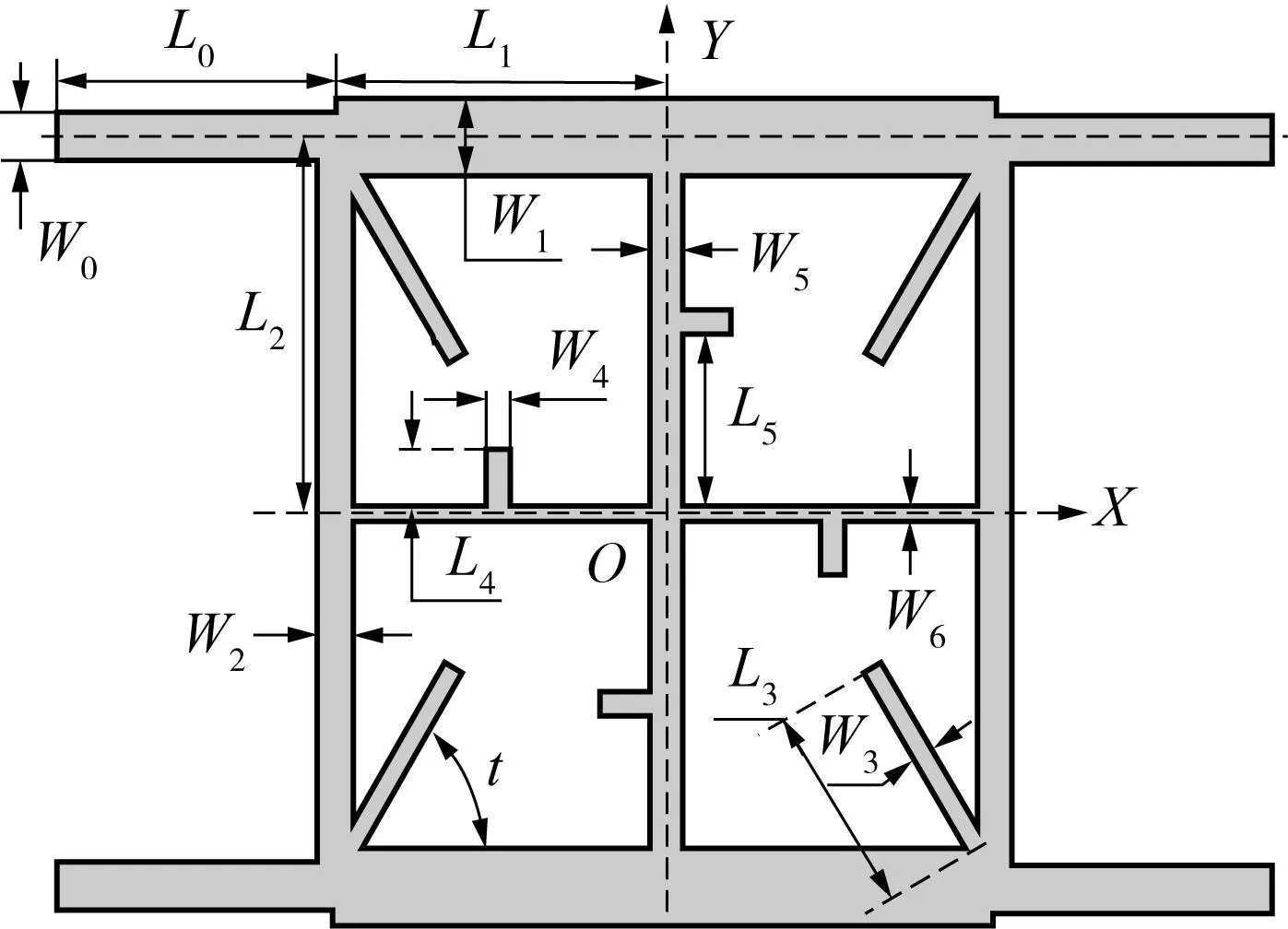
图1 宽频带双频段功分器模型 Fig.1 Broadband dual band power divider model

(a)基本耦合器(b)宽频带单频耦合器
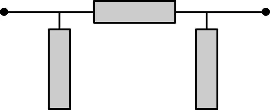

图2宽频带双频段耦合器关键结构
Fig.2Key structure of broadband dual band coupler


运算整理得

其中Y=Y3tanθ3.
此外,上面的表达式可以进一步整理:
(1)
其中,
Z1sinθ1=±ZT
(2)
(3)

图2(d)为双频微带线T型等效电路,对应的电路参数见图3,通过推导可得对应T型结构的转移矩阵:
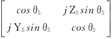
运算整理得
(4)
其中,
Z5tanθ5=±ZC
(5)
从方程(4)可以看出,T型结构相当于特性阻抗为ZC、电长度为90°的微带传输线.
(6)
其中θ5和θ5′对应于中心频率f1和f2对应的微带线电长度.同样,此T型结构可以获得双频带特性.
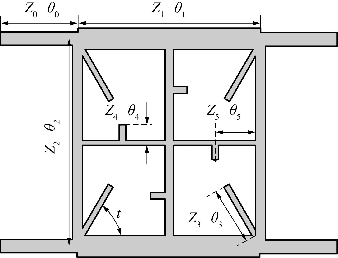
图3 宽频带双频段功分器电路图 Fig.3 Circuit diagram of the broadband dual band power divider
开路分支线Z3的角度和长度均对功分器输出功分比有影响.如图4所示,当角度t=0.785rad,也就是45°时,开路分支线与两边微带线之间夹角相同,此时开路分支线长度L3的变化对输出功分比基本无影响.但是高频部分谐振频率随着L3增大稍有减小,这是因为长度L3影响了双频特性中的高频部分.
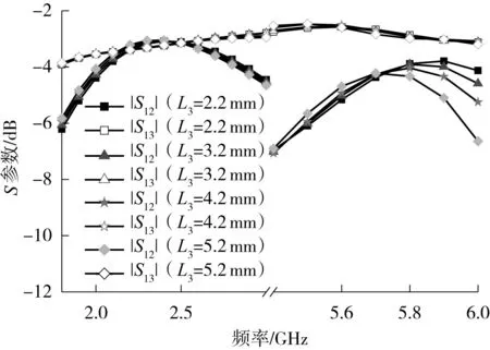
图4 t=0.785rad时L 3对功分比的影响 Fig.4 Effects of L 3 on power division ratios when t=0.785rad

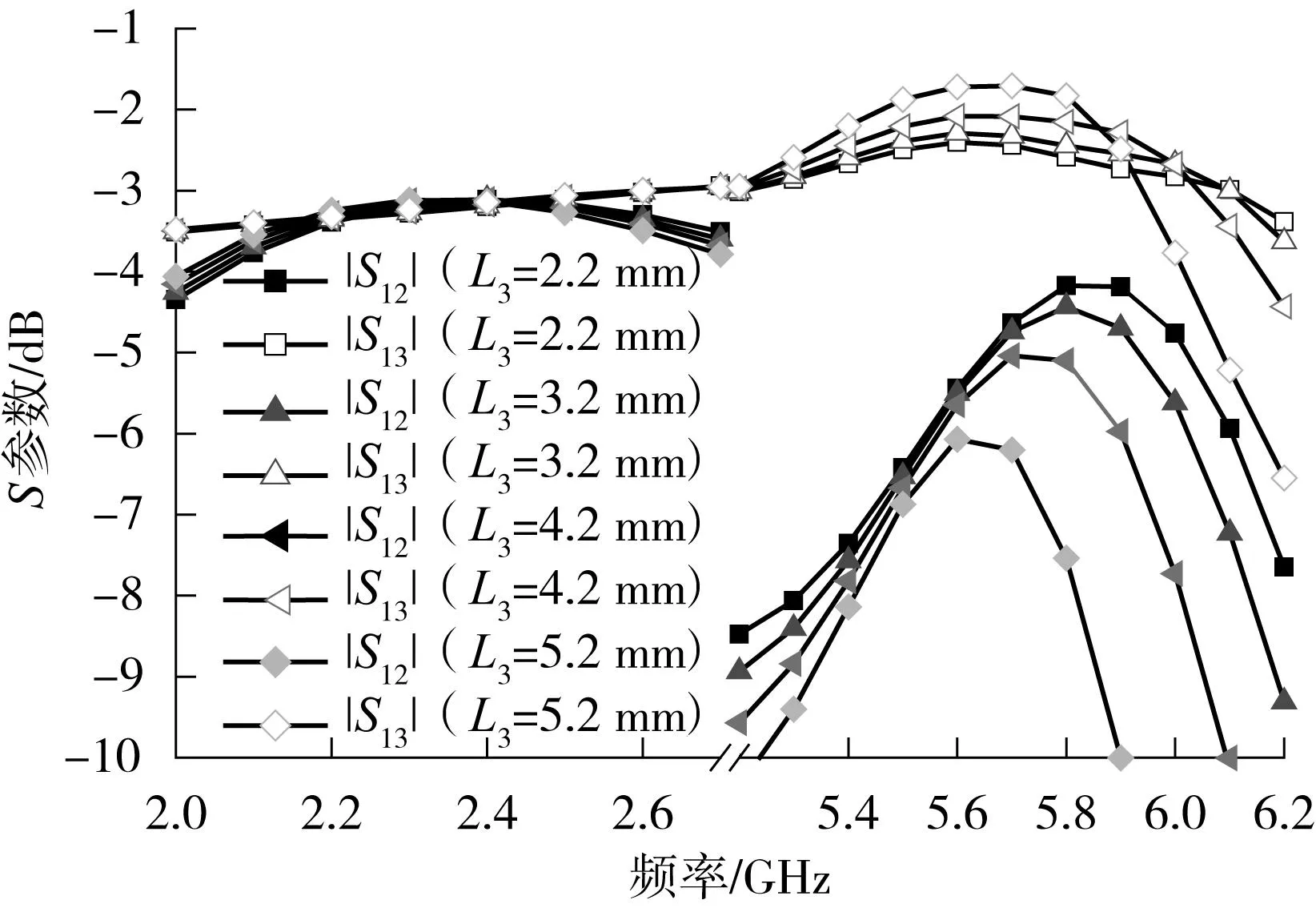
图5 t=1.1rad时 L 3对功分比的影响 Fig.5 Effects of L 3 on power division ratios when t=1.1rad
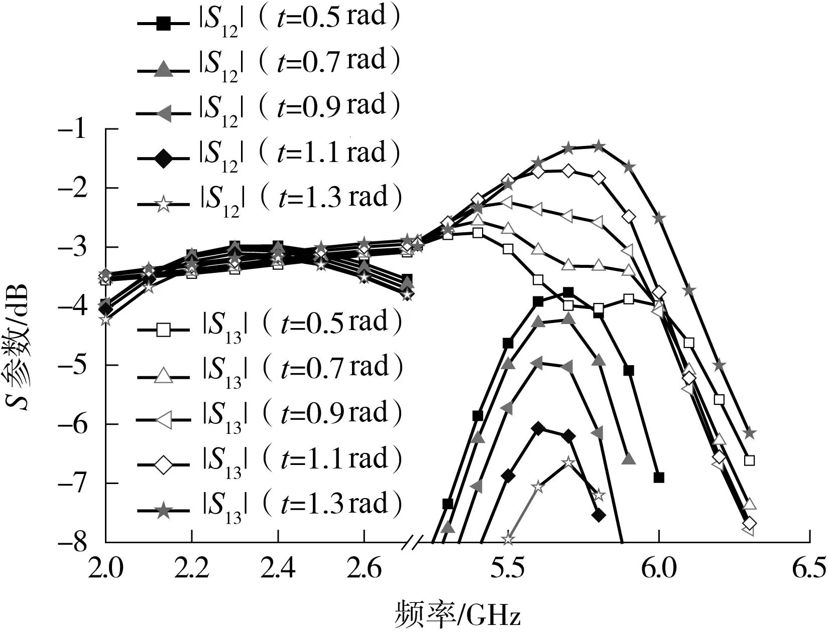
图6 L 3=6.2mm时角度t对功分比的影响 Fig.6 Effects of angle t on power division ratios when L 3=6.2mm
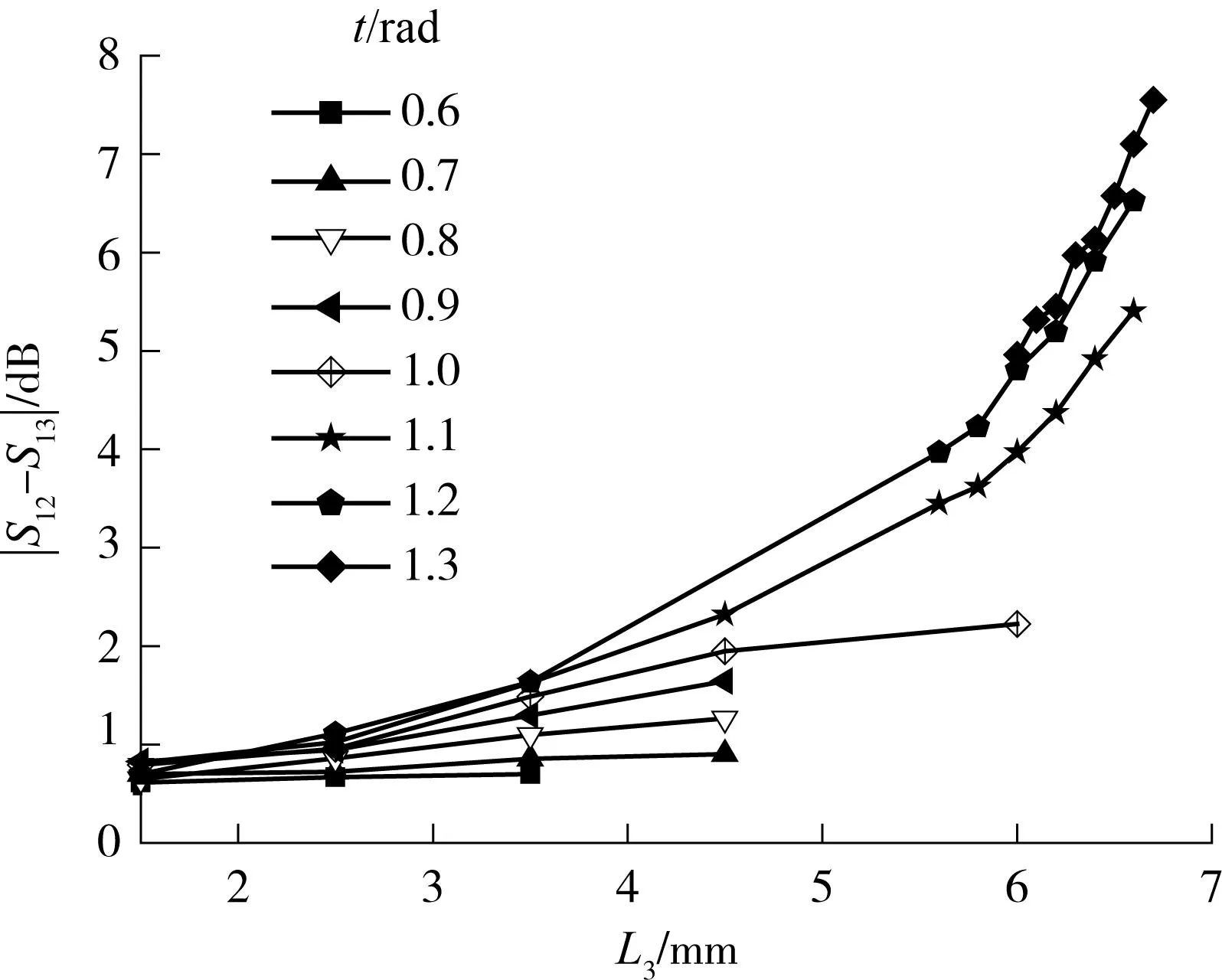
图7 开路分支线的角度t和长度L 3对5.8GHz频段功 分比的影响 Fig.7 Effects of angle t and length L 3of the open stub on the power division ratio at 5.8GHz
文中提出的新型正交耦合器覆盖两个常用的多波束电子不停车收费(ETC)系统工作频段:2.4GHz(2.2~2.6GHz)和5.8GHz(5.5~6.0GHz),在介电常数为3.55的介质板上的波长分别为66.34mm和27.45mm.L3在2.5mm至6.7mm的变化范围内小于2.4GHz频段波长的十分之一,而大于5.8GHz频段波长的十分之一,所以对2.4GHz频段输出功分比没有明显的影响,基本保持等功分比输出,而对于5.8GHz频段输出功分比影响明显,变化范围为0.6dB至7.3dB.
2结果与讨论
文中选取的电路材料为Rogers RO4003,介电常数为3.55,损耗角正切为0.0027,介质厚度为0.508mm.文中设计的双频段功分器如图8所示,在2.4GHz频段都是等功分比的,在5.8GHz频段功分比分别为0.6、4.5和7.3dB,经过仿真优化,所得5.8GHz频段4.5dB功分比电路最佳的S参数相应的电路结构参数如表1所示.
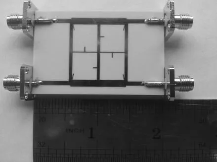
表15.8GHz4.5dB功分比双频段功分器设计参数
Table 1Parameters of the proposed dual band power divider with a power divider ratio of 4.5 dB at 5.8GHz
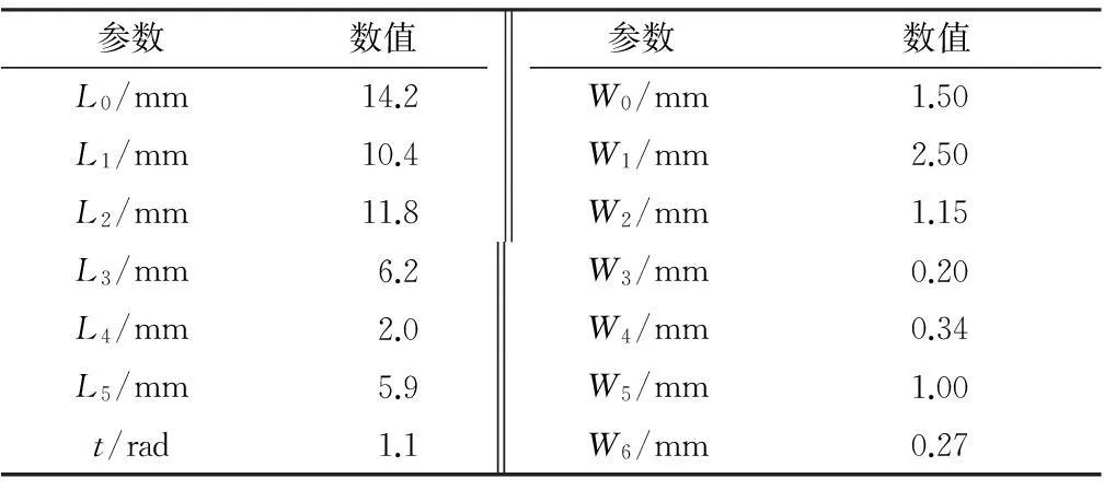
参数数值参数数值L0/mm14.2W0/mm1.50L1/mm10.4W1/mm2.50L2/mm11.8W2/mm1.15L3/mm6.2W3/mm0.20L4/mm2.0W4/mm0.34L5/mm5.9W5/mm1.00t/rad1.1W6/mm0.27
5.8GHz频段0.6dB功分比电路仅需要使表1中参数t=1.1rad,L3=2.5mm.5.8GHz 频段7.3dB功分比电路仅需要使表1中的参数t=1.3rad,L3=6.7mm.
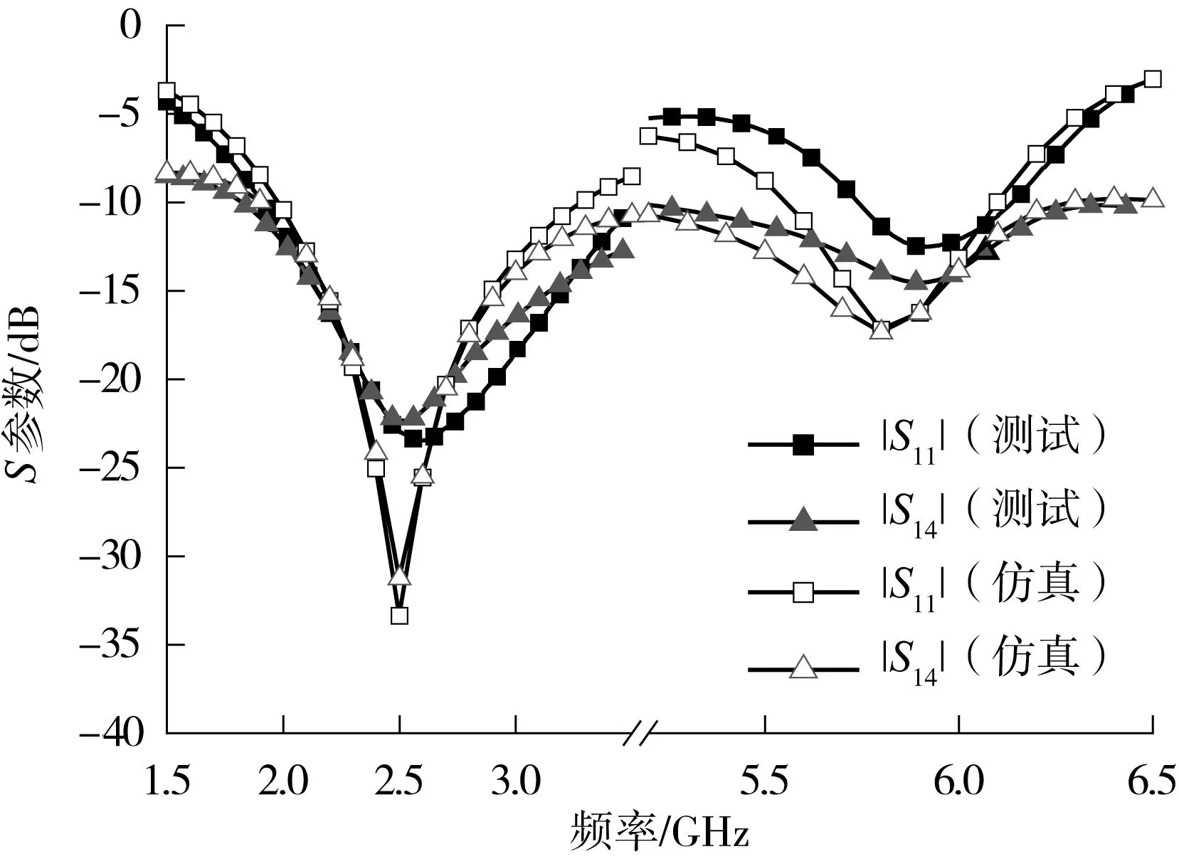
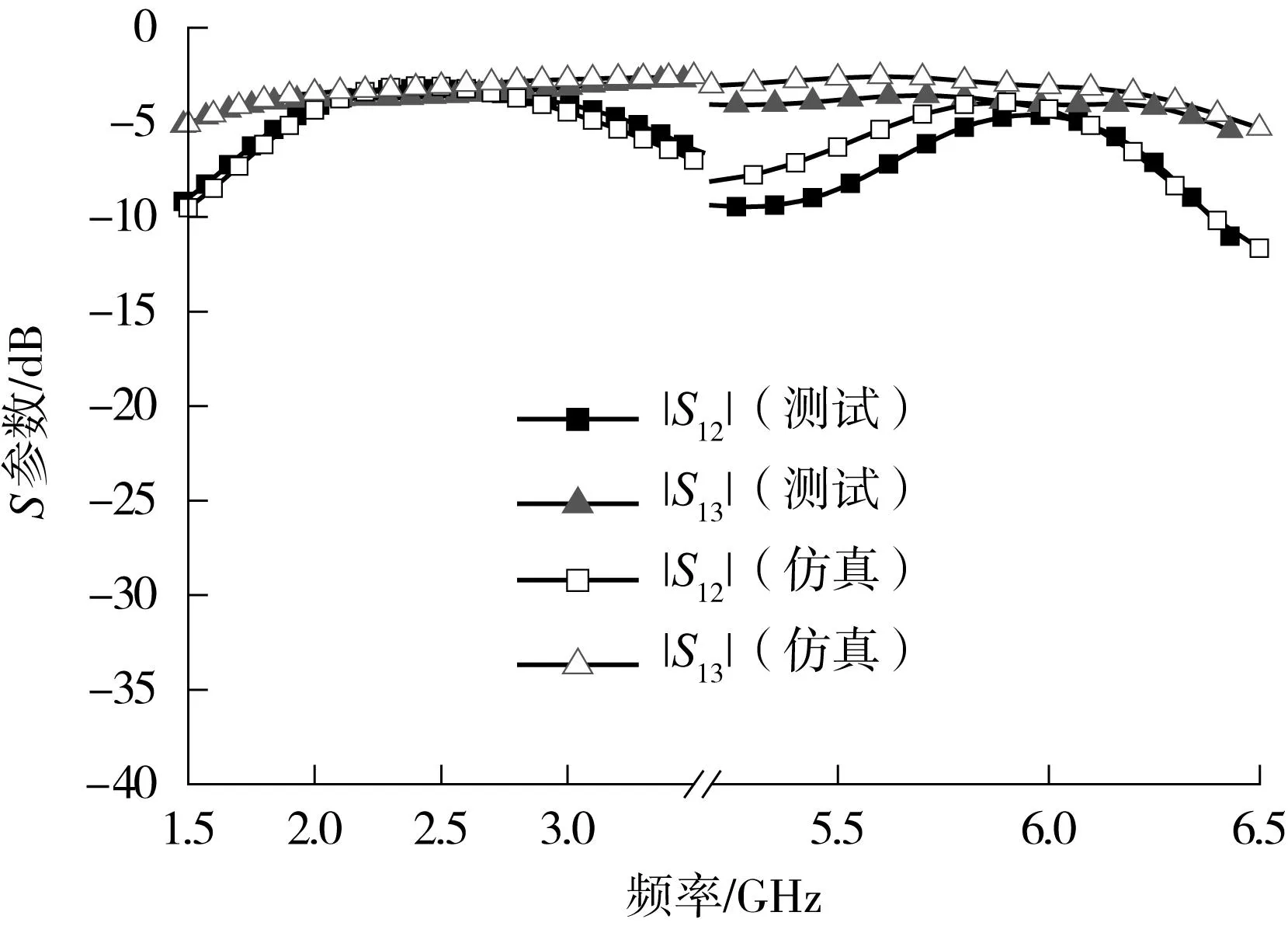
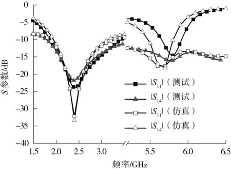
图9、10示出了在5.8GHz频段不同功分比的3个功分器仿真和实物测试中的S参数以及输出端口相位差的对比结果.
(a)功分比为0.6dB时的 S 11、 S 14参数
(b)功分比为0.6dB时的 S 12、 S 13参数
(c)功分比为4.5dB时的 S 11、 S 14参数
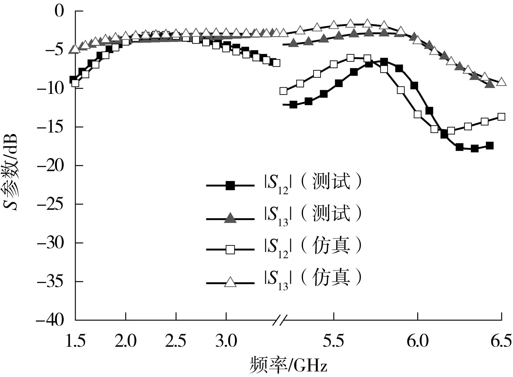
(d)功分比为4.5dB时的 S 12、 S 13参数
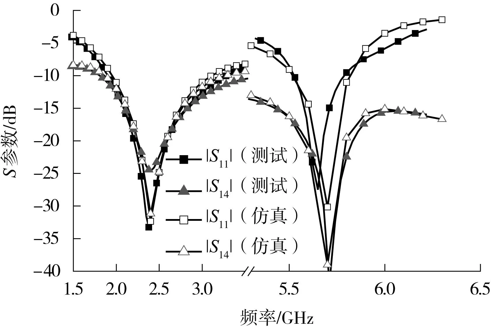
(e)功分比为7.3dB时的 S 11、 S 14参数
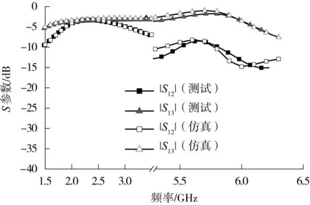
(f)功分比为7.3dB时的S 12、S 13参数 图9 双频段功分器仿真和测试S参数结果 Fig.9 Simulated and measured S-parameters of the proposed dual band power divider
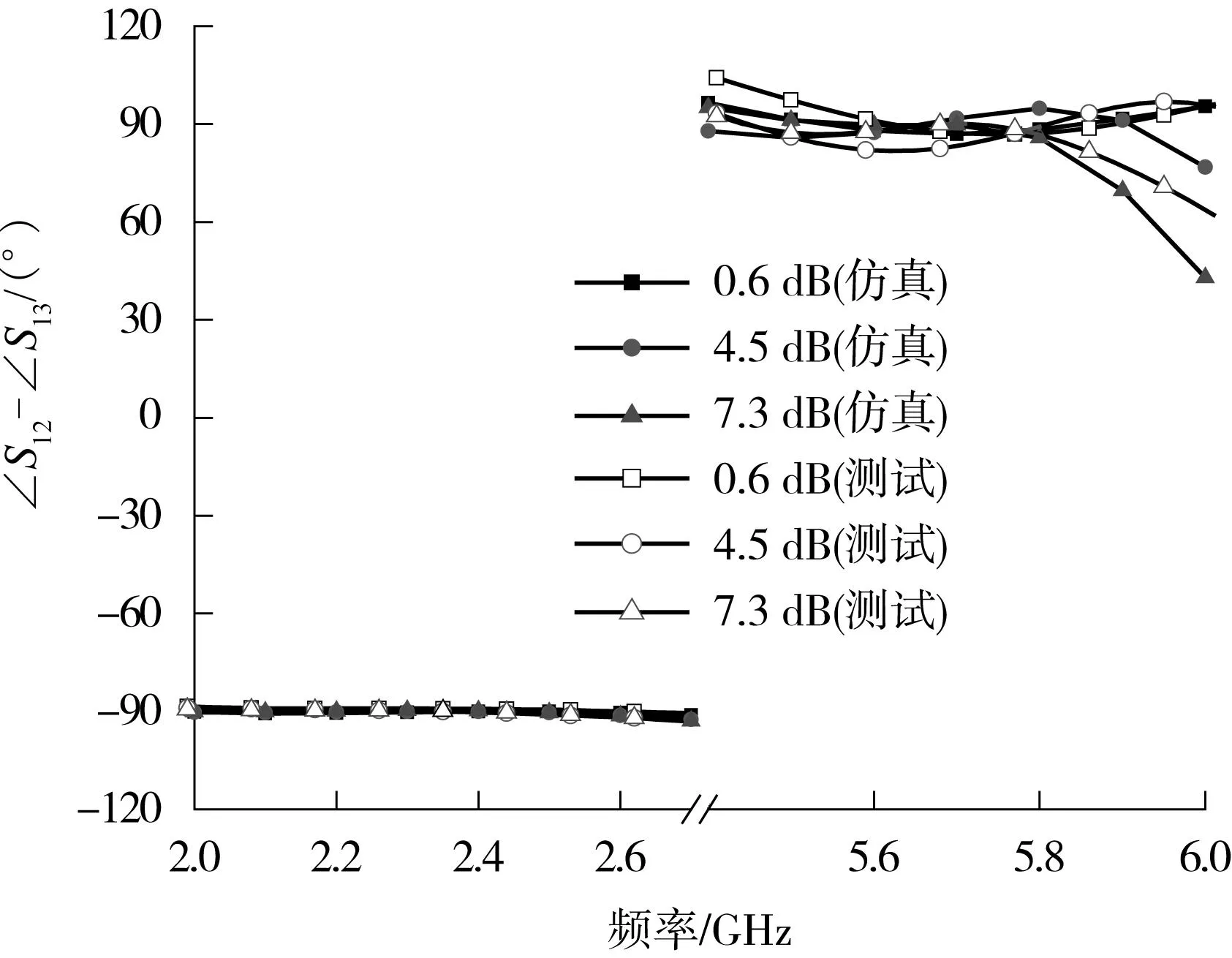
图10 双频段功分器仿真和测试中的输出端口相位差 Fig.10 Simulated and measured phase difference at out ports of the proposed dual band power divider
调节t和L3的值分别为1.1rad和2.5mm,对应仿真和测试结果如图9所示.图9(a)中,在5.7~6.0GHz频段,反射系数|S11|仿真和测试数据都小于-10dB,隔离度|S14|小于-12dB.输出端口(端口2和端口3)的仿真功分比在5.65~5.95GHz,频段为0.9~1.2dB,测试功分比在5.7~6.0GHz,频段为0.6~1.2dB,此频率偏差由制造误差引起.在2.2~2.6GHz,反射系数和隔离度的仿真和测试数据都小于-15dB,输出端口的功分比为0 ~0.3dB(输出端口值在-3.36~-3.02dB范围内).实现两个输出端口在2.4GHz频段内等功分比输出,在5.8GHz频段最小输出功分比为0.6dB.除去制造误差,仿真和测试结果吻合良好.
t和L3的值分别调节为1.1rad和6.2mm,对应仿真和测试结果见图9(c)和(d).在5.5~5.8GHz频段的仿真数据,分别为反射系数小于-10dB,隔离度小于-15dB,输出功分比在4.4-5.5dB范围内.在5.6~5.9GHz频段的测试数据,分别为反射系数小于-10dB,隔离度小于-15dB,输出功分比在3.9~4.9dB范围内.测试和仿真的频率、功分比偏差由制造误差引起.在2.2~2.6GHz,反射系数和隔离度的仿真和测试数据都小于-15dB,输出端口的功分比为0~0.3dB(输出端口值在-3.36~-3.02dB范围内).实现两个输出端口2.4GHz频段(带宽为400MHz)为等功分比,在5.8GHz频段(带宽为300MHz)输出功分比为4.5dB.除去制造误差,仿真和测试结果吻合良好.
进一步通过调节t和L3分别为1.3 rad和6.7mm,对应仿真和测试结果见图9(e)和(f).在5.5~5.8GHz频段的仿真数据,分别为反射系数小于-10dB,隔离度小于-15dB,输出功分比在7.1~7.4dB范围内.在5.55~5.85GHz频段的测试数据,分别为反射系数小于-10dB,隔离度小于-15dB,输出功分比在6.5~7.3dB范围内.测试和仿真的频率、功分比偏差由制造误差引起.在2.2~2.6GHz,反射系数和隔离度的仿真和测试数据都小于-15dB,输出端口的功分比为0~0.3dB.实现了两个输出端口2.4GHz频段内等功分比输出,在5.8GHz频段最大输出功分比为7.3dB.除去制造误差,仿真和测试结果吻合良好.
从图10中可以看到,在2.4GHz频段的400MHz频带宽度内和5.8GHz频段300MHz的频带宽度内,两个输出端口(端口2和端口3)都满足+90°或-90°的相位差,满足正交的相位条件.
综上所述,仿真和实测结果表明,通过调节参数L3和t的值,可实现2.4GHz频段等功分比正交输出,而在5.8GHz频段,连续可调功分比范围为0.6~7.3dB,最终实现双频正交功分器.
3结语
文中提出一种在ETC系统中应用的新型双频段正交等分比和不等分比功分器,这种功分器的工作频率覆盖2.4GHz频段(2.2~2.6GHz)和5.8GHz频段(5.5~6.0GHz),2.4GHz频段等功分比输出,在5.8GHz频段可以通过调节参数实现0.6~7.3dB任意比例功分比输出,并且在两个频段上两个输出端口都是正交的,电路尺寸小(50mm×28mm),实物测试数据和仿真数据吻合良好.文中提出的新型双频功分器可以在ETC系统中发挥良好的作用,利用5.8GHz频段的宽频范围优势,将本功分器的任意功分比性能应用于多波束Butler 矩阵的设计,实现多车道自由流检测系统.本设计也为其他需要用到双频段正交等分比和不等分比功分器的应用场合提供了一个良好的解决方案.
参考文献:
[1]Jin S,Han R,Arigong B,et al.A dual-band microstrip crossover and its miniaturization [C]∥Proceedings of Antennas and Propagation Society International Sympo-sium (APSURSI).Chicago:IEEE,2012.
[2]Liu X,Yu C,Liu Y,et al.A novel compact planar crossover with simple design procedure [C]∥Proceedings of Asia-Pacific Microwave Conference 2010 (APMC 2010).Yokohama:IEEE,2010.
[3]Fai-Leung W,Cheng K K M.A novel,planar,and compact crossover design for dual-band applications [J].IEEE Transactions on Microwave Theory and Techniques,2011,59(3):568-573.
[4]Lee Z W,Pang Y H.Compact planar dual-band crossover using two-section branch-line coupler [J].Electronics Letters,2012,48(21):1348-1349.
[5]Ching-Luh H.Design of quadrature hybrid with closely separated dual-passband using three-branch line coupler[C]∥Proceedings of Asia-Pacific Microwave Conference 2010 (APMC 2010).Yokohama:IEEE,2010.
[6]Chilhyeun G,Kwansun C,Inho N,et al.A new branch-line hybrid coupler with arbitrary power division ratio [C]∥Proceedings of Asia-Pacific Microwave Conference 2007 ( APMC 2007).Bangkok:IEEE,2007.
[7]Kholodniak D,Kalinin G,Vernoslova E,et al.Wideband 0-dB branch-line directional couplers [C]∥Proceedings of 2000 IEEE MTT-S International Microwave Symposium Digest.Boston:IEEE,2000.
[8]Jin S,Han R,Arigong B,et al.A fully symmetrical crossover and its dual-frequency Application [J].IEEE Transactions on Microwave Theory and Techniques,2012,60(8):2410-2416.
[9]Reed J,Wheeler G J.A method of analysis of symmetrical four-port networks [J].IRE Transactions on Microwave Theory and Techniques, 1956,4(4):246-252.
[10]Cheng K K M,Fai-Leung W.A novel approach to the design and implementation of dual-band compact planar 90° branch-line coupler [J].IEEE Transactions on Microwave Theory and Techniques,2004,52(11):2458-2463.
[11]Hualiang Z,Chen K J.A stub tapped branch-line coupler for dual-band operations [J].IEEE Microwave and Wireless Components Letters,2007,17(2):106-108.
[12]Ching-Luh H.Dual-band branch line coupler with large power division ratios [C]∥Proceedings of Asia-Pacific Microwave Conference 2009 (APMC 2009).Singapore:IEEE,2009.
[13]Zheng S Y,Wu Y,Li Y,et al.Dual-band hybrid coupler with arbitrary power division ratios over the two bands [J].IEEE Transactions on Components,Packaging and Manufacturing Technology,2014,4(8):1347-1358.
[14]Sinchangreed V,Uthansakul M,Uthansakul P.Design of tri-band quadrature hybrid coupler for WiMAX applications [C]∥Proceedings of 2011 International Symposium on Intelligent Signal Processing and Communications Systems (ISPACS).Chiang Mai:IEEE,2011.
[15]林峰,诸庆昕.新型三频环形耦合器的设计 [J].华南理工大学学报:自然科学版,2011,39(7):26-31.
Lin Feng, Chu Qing-xin.Design of a novel tri-band rat race coupler [J].Journal of South China University of Technology:Natural Science Edition,2011,39(7):26-31.
[16]Yao J J.Nonstandard hybrid and crossover design with branch-line structures [J].IEEE Transactions on Microwave Theory and Techniques,2010,58(12):3801-3808.
Dual-Band Orthogonal Power Divider with Variable Power Division
Ratio Applied to ETC System
LiHong-tao1WeiXiao-Dong1HuBin-Jie1ZhangHong-lin1ZengWei-sen2
(1. School of Electronic and Information Engineering, South China University of Technology, Guangzhou 510640, Guangdong, China;
2. Faculty of Automation, Guangdong University of Technology, Guangzhou 510006, Guangdong, China)
Abstract:Proposed in this paper is a novel orthogonal Hybrid coupler applied to multi-beam electronic toll collection (ETC) systems. In this coupler, two common frequency bands of ETC system including 2.4GHz (2.2~2.6GHz) and 5.8GHz (5.4~6.0GHz) are covered to adapt different working frequency bands, and different power distribution characteristics are endowed in the two frequency bands, that is, equally orthogonal output in 2.4GHz band and orthogonal output in the range of 0.5~7dB in 5.8GHz band. The proposed divider is of broad bandwidth and small circuit size, and, it is proved feasible due to the good agreement between real test results and simulation data.
Key words: power divider; dual band; coupler; variable power division ratio; broadband
Foundation items: Supported by the National Natural Science Foundation of China(NSFC)(61102069, 61301105) and the Natural Science Foundation of Jiangsu Province(BK20140828)

